APV RH 600 M1 User manual

TRANSLATION OF THE ORIGINAL OPERATING MANUAL
Version: 2.2 EN / Item no.: 00601-3-374
Operating manual RH 600 M1
Please read carefully before initial operation!

Page 2
Table of Contents
1 EC Declaration of Conformity............................................................................................. 3
2 Warranty............................................................................................................................... 4
3 Service ................................................................................................................................. 4
4 Location of the type plate ................................................................................................... 4
5 Safety instructions .............................................................................................................. 5
5.1 Intended use.............................................................................................................. 5
5.2 General safety-related instructions and accident prevention regulations .................... 5
5.3 Mounted implements.................................................................................................. 6
5.4 Towed implements..................................................................................................... 7
5.5 Hydraulic system........................................................................................................ 7
5.6 Maintenance .............................................................................................................. 7
5.7 Tyres.......................................................................................................................... 8
6 Safety signs ......................................................................................................................... 9
7 Technical data ................................................................................................................... 11
8 Road transport................................................................................................................... 12
8.1 General.................................................................................................................... 12
8.2 Calculation of the weight ratios ................................................................................ 12
9 Layout and mode of operation ......................................................................................... 14
9.1 Working position and setting the working depth and pitch........................................ 15
9.2 Quick lifting device (installed as a standard) ............................................................ 16
10 Operation ........................................................................................................................... 18
10.1 Mounting on the tractor ............................................................................................ 18
10.2 Safe parking............................................................................................................. 18
10.3 Test folding .............................................................................................................. 18
11 Maintenance and care....................................................................................................... 19
11.1 Maintenance and care instructions........................................................................... 19
11.2 Changing the star rings/bearing ............................................................................... 20
12 Hydraulic diagram ............................................................................................................. 21
13 Lighting circuit diagram.................................................................................................... 22
14 Combination options with PS........................................................................................... 23
15 Crop cultivation tips when using the rotary hoe............................................................. 24
15.1 Hitting the right growth phase................................................................................... 24
15.2 Applications ............................................................................................................. 25
16 Accessories ....................................................................................................................... 26
17 Index................................................................................................................................... 29

Page 3
1 EC Declaration of Conformity
according to the EC Machinery Directive 2006/42/EC
We hereby declare that the implement (exchangeable equipment) described in the following meets the
basic safety requirements in Annexe I of the EC Machinery Directive 2006/42/EC.
This declaration loses its validity in cases of non-intended use and if changes are made to the implement
that were not approved by the manufacturer.
Manufacturer: APV-Technische Produkte GmbH,
Headquarters, Dallein 15, AT-3753 Hötzelsdorf, Austria
Product designation: Rotary hoe RH 600 M1
Number: RH 600 M1
Serial number: all serial numbers for the Rotary hoe RH 600 M1
Legal authorised person
for the technical documents: APV-Technische Produkte GmbH,
Headquarters, Dallein 15, AT-3753 Hötzelsdorf, Austria
Conformity procedure: Machinery Directive 2006/42/EC Annex I
Conformity with the following directives:
2006/42/EC Machinery Directive
2014/30/EC EMC Directive
Applicable standards:
EN 349:1993 Safety of machinery – Minimum gaps to avoid crushing of parts of the human body
EN ISO 14120:2015 Safety of machinery – Guards
EN 60204-1:2006 Safety of machinery – Electrical equipment
EN ISO 12100:2010 Safety of machinery; General principles for design; Risk assessment and risk
reduction
EN ISO 13857:2008 Safety of machinery – Safety distances
EN ISO 14982:2009 Agricultural and forestry machinery ―Electromagnetic compatibility ―Test
methods and acceptance criteria
EN ISO 4254-1:2015 Agricultural machinery – Safety - General requirements
Dallein, 12/2019
City, Date
Signature
Ing. Jürgen Schöls
Management

Page 4
Figure 1: Position of the production number
2 Warranty
Please check the implement for any transport damage immediately upon receipt. Later claims regarding
transport damage can no longer be considered.
We provide a six-month factory warranty as of the date of delivery (your invoice or the delivery slip serve
as a warranty certificate).
This warranty is applicable for cases of material or construction faults and does not include parts that are
damaged by normal or excessive wear.
The warranty expires
•if damage is caused by external forces.
•in cases of operating errors.
•if the kW/HP limits are significantly exceeded.
•if the implement is modified, expanded or equipped with third-party spare parts without our
permission.
3 Service
Please contact our service address in the following cases:
•If you still have questions regarding the handling of the rotary hoe despite the information provided
in this operating manual
•For spare parts orders
•To order maintenance and repair work
Service address:
APV - Technische Produkte GmbH
HEADQUARTERS
Dallein 15
AT-3753 Hötzelsdorf
AUSTRIA
Telephone: +43 (0) 2913 8001
Fax: +43 (0) 2913 8002
Email: service@apv.at
Web: www.apv.at
4 Location of the type plate
The type plate is found on the main frame on the mounting frame bracket.
The following image (Figure 1) shows the layout of the type plate:
The data on the type plate have the following
meaning:
No.
Meaning
1 Designation
2 Model
3 Production number
4 Weight
5 Year of manufacture
PLEASE NOTE!
In cases of inquiries or warranty claims, please be sure to always tell us the production
number of your implement.

Page 5
5 Safety instructions
This chapter contains general rules of conduct for the intended use of the implement and safety-
related information that should always be observed for your safety.
The list is very extensive, and some of the information does not apply exclusively to the delivered
implement. However, the summary of the information often reminds you of unconsciously neglected
safety regulations for the everyday operation of machines and implements.
The general accident prevention regulations of the respective countries must be observed. Always
secure the parked implement against unintentional rolling. The implement may only be used by persons
who are informed of the hazards and who know the regulations for transport on public roads.
5.1 Intended use
The implement is designed solely for normal use in agricultural operations (intended use).
Any other use is considered to be non-intended. The manufacturer is not liable for any resulting damage,
the operator alone bears the associated risk.
Intended use also includes compliance with the conditions for operation, maintenance, and repairs
prescribed by the manufacturer.
The implement may only be used, maintained and repaired by persons who have relevant experience
and were instructed on the risks. The safety instructions must also be handed over to other users.
The applicable accident prevention regulations as well as the other generally safety-related,
occupational health and road traffic regulations must also be observed.
The manufacturer is not liable for any damage resulting from unauthorised modifications and the use of
components and auxiliary parts.
The implement is intended for operation at temperatures between +5°C and +40°C.
The rotary hoe is intended for operation outdoors during dry weather. Water penetration must be
avoided. Do not use the rotary hoe in rainy conditions!
5.2 General safety-related instructions and accident prevention
regulations
•Check the implement and the tractor for road and operational safety before every use!
•Observe the generally applicable safety and accident prevention regulations!
•The warning and information signs applied to the implement provide important instructions for safe
operation, observe them for the sake of your own safety!
•Observe the respective regulations when using public roads!
•Before starting work, get to know all of the equipment and operating elements as well as their
functions. It is too late to do so during operation!
•The user should wear close-fitting clothing. Avoid wearing loose clothes!
•Keep the implements clean to reduce the risk of fire!
•Check the surrounding area before starting up and operating the implement! (Children!) Ensure
sufficient visibility!
•It is not allowed to carry passengers on the implement during operation and transport!
•The implement must be coupled according to the instructions and only onto the specified devices!
•Special care must be taken when coupling and uncoupling implement to and from the tractor!
•When mounting and dismounting, put the support devices in their respective positions! (Stability)
•Always attach ballast weights at the intended attachment points according to the specifications!
•Observe the permissible axle load, total weight and transport dimensions!

Page 6
•Transport equipment - e.g. lighting, warning signs and any protective equipment, must be checked
and mounted!
•Triggers for fast couplers must be hanging loosely and must not trigger themselves when lowered.
•Never leave the driver's platform while driving!
•The driving behaviour, steering and braking capacity are also affected by mounted or towed
implements and ballast weights. For this reason, always ensure sufficient steering and braking
capacity!
•When driving in curves, take account of the wide radius and/or the centrifugal mass of the
implement!
•The implement may only be operated when all of the protective devices are installed and in safety
position!
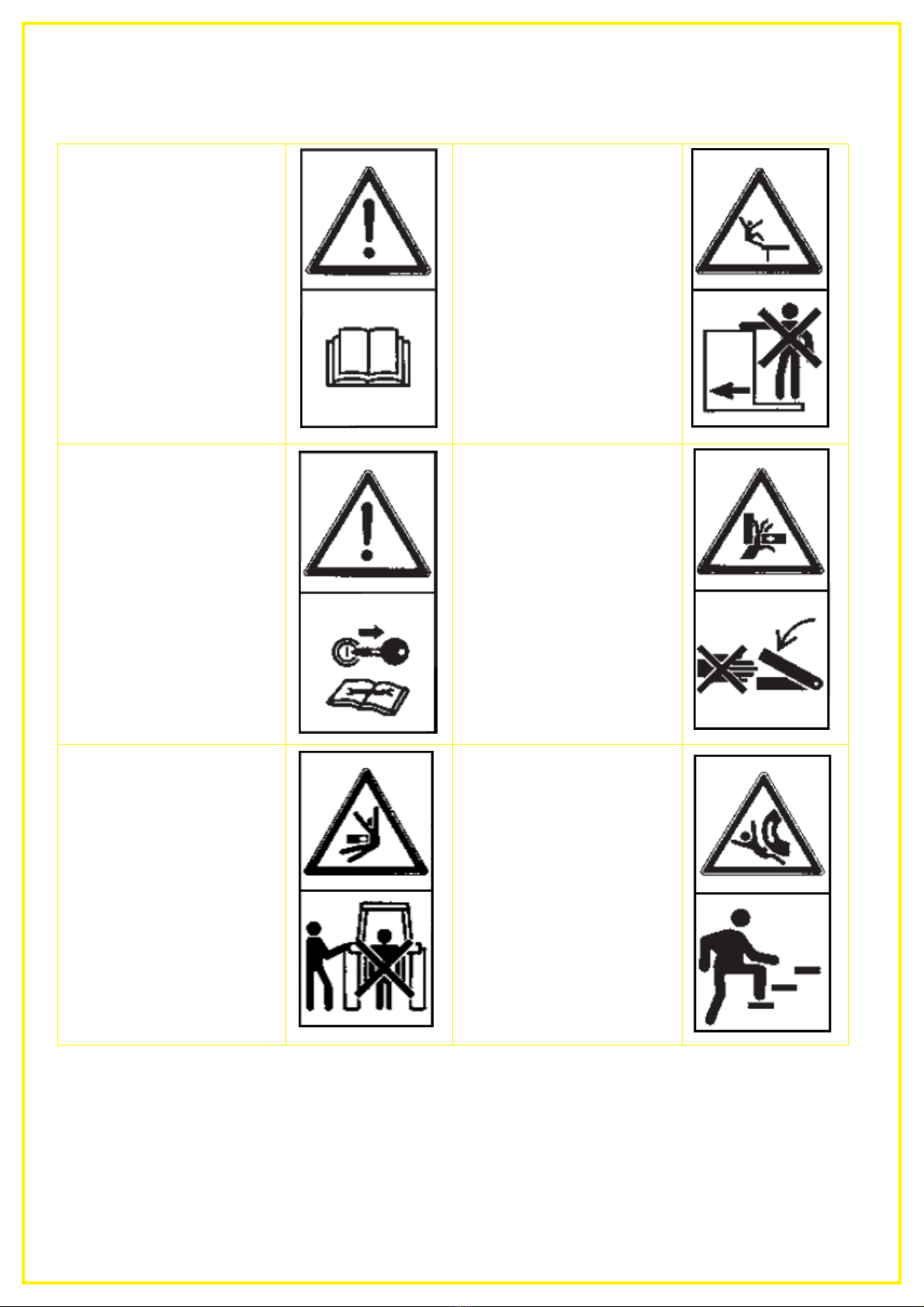
•It is forbidden to stand in the working area of the implement!
•Do not stand near rotating and swivelling parts of the implement!
•Hydraulic folding frames may only be actuated when nobody is standing in the swivelling range.
•There are pinch and shear points on externally powered (e.g. hydraulic) parts!
•On implements with manual folding, always ensure that the implement is stable!
•For implements that are driven rapidly with soil-driven tools - Danger after lifting due to the still
rotating centrifugal mass! Only approach the implement when it has come to a standstill!
•Before exiting the tractor, lower the implement onto the ground, switch off the motor and remove the
ignition key!
•Standing between the tractor and the implement is forbidden unless the vehicle is secured against
rolling away using the parking brake and/or with wheel chocks!
•Folded frames and lifting devices must be locked in transport position!
•Packer catch arms must be swivelled in and locked before road transport!
•Lock the track markers in transport position!
•The rotary hoe may only be used on agricultural land. It may not be used on normal road surfaces,
on asphalt or concrete. In particular, the rotary hoe may not be used in the building industry on
construction sites, for winter services, for road construction, or for underground mining.
•When driving on roads, which is only permitted with folded side wings and the rotary hoe raised, the
tractor hydraulic system prevents lowering of the rotary hoe as well as of the folded up components
(additionally secured with a chain), also in case of failure of the tractor hydraulic system.
•The specifications in the operating manual regarding mounting as well as the calculation of the
weight ratios and the axle loads of the tractor must be observed.
•No other persons may be in the hazard area of the rotary hoe. Visual check by the driver!
•When performing the work passes, the tractor's speed must maintained as specified in the operating
instructions. This can be between 2 and 25 km/h.
•People must not be carried on the rotary hoe during intended use on agricultural land and when
driving on roads.
•When mounting the rotary hoe, the operator must ensure that there is a metallic connection made to
the tractor.
•The view of the rotary hoe and the hazardous movement area must be clear to check the procedure.
•During assembly, the operator must ensure that the requirements for the tractor in terms of the
power, axle loads and weight distribution as specified in the operating manual are met and that the
connections specified in the operating instructions are made correctly.
•Hearing protection should be used, if necessary.
•The implements must be checked regularly by the operator (before every use) for any fractures and
cracks, chafe marks, leaks, loose bolts and connections, vibrations, unusual sounds, and to ensure
they function correctly.
•The implement may not be used during storms and rain, and it must be parked under a shelter.
•The operator must ensure that no one is in the vicinity of the rotary hoe when it or its components are
being moved by the tractor's hydraulic system. Visual check by the driver!
5.3 Mounted implements
•Before mounting and dismounting implements on the three-point linkage, move the operating devices
into the position that excludes unintentional lifting or lowering!

Page 7
•For three-point mounting, the mounting categories of the tractor and the implement must match or be
adapted!
•There is a risk of injury due to crushing and shearing points in the area of the three-point linkage!
•Do not stand between the tractor and the implement when actuating the external controls for the
three-point mounting!
•When the implement is in transport position, always ensure that the tractor three-point linkage is
sufficiently locked to the sides!
•When driving on roads with the implement lifted, the operating lever must be locked against lowering!
5.4 Towed implements
•Secure the implement against rolling away.
•Observe the max. permissible drawbar load of the trailer coupling, tractor drawbar, or hitch!
•With a drawbar hitch, sufficient mobility on the attachment point must be ensured.
5.5 Hydraulic system
•The hydraulic system is under high pressure!
•When connecting hydraulic cylinders and motors, the specified connection of the hydraulic hoses
must be observed.
•When connecting the hydraulic hoses to the tractor hydraulic system, make sure that the hydraulic
system on the tractor and implement side is unpressurised!
•For hydraulic function connections between the tractor and the implement, coupling sleeves and
connectors should be marked to rule out operating errors! If the connections are interchanged, the
function will be inverted (e.g. lifting/lowering) - risk of accident.
•Inspect the hydraulic hose lines at regular intervals and replace in case of damage or wear! The
replacement lines must comply with the technical requirements of the implement manufacturer!
•Due to the risk of injury, use suitable tools when searching for leaks!
•Liquids escaping under high pressure (hydraulic oil) can penetrate skin and cause serious injuries!
Consult a doctor immediately in case of injury! (Risk of infection!)
•Before working on the hydraulic system, park the implement, depressurize the system and switch off
the motor!
•The securing chain should only be unhooked when it is relieved of tension! (Cylinder must be filled
with oil.)
•When mounting the implement, the operator must ensure that connections to the tractor hydraulic
system are clean and carefully connected.
5.6 Maintenance
•Maintenance, repair, and cleaning work as well as the elimination of malfunctions should always be
performed when the drive is switched off and the motor is at a standstill! – Remove the ignition key!
•Check the nuts and bolts regularly for tight fit and retighten if necessary!
•When performing maintenance on the lifted implement, always ensure safety through suitable
support elements!
•When changing work tools with sharp edges, always use suitable tools and gloves!
•Properly dispose of oils, grease and filters!
•Always cut the power supply when working on the electrical system!
•When performing electrical welding work on the tractor and mounted implement, disconnect the
cable on the generator and the battery!
•Spare parts must at least comply with the technical requirements specified by the implement
manufacturer! This is ensured with original parts! PTO shaft operation (only for PTO shaft-driven
implements)
•.Only universal joint shafts prescribed by the manufacturer can be used!
•The guard tube and funnel for the universal joint shaft as well as the PTO shaft guard, also on the
implement side, must be installed and be in proper condition.

Page 8
•For universal joint shafts, pay attention to the prescribed tube covers in transport and working
position.
•The universal joint shaft may only be mounted and dismounted when the PTO shaft and the motor
are switched off and the ignition key is removed.
•Always ensure that the universal joint shaft is properly mounted and locked.
•Secure the universal joint shaft guard against rotating along by hooking in the chain.
•Before switching on the PTO shaft, ensure that the selected PTO shaft speed of the tractor matches
with the permissible speed of the implement.
•When using the ground speed PTO, ensure that the rpm is forward speed-dependent and that the
direction of rotation is inverted when driving in reverse.
•Before switching on the PTO shaft, ensure that nobody is standing in the danger zone of the
implement.
•Never switch on the PTO shaft when the motor is switched off.
•When working with the PTO shaft, nobody may be standing in the area of the rotating PTO shaft or
universal joint shaft.
•Always switch off the PTO shaft if too much angular deflection occurs and it is not required.
•Caution after switching off the PTO shaft: Danger due to centrifugal mass that is still rotating.
•Do not get too close to the implement during this time. Work can only be performed when it comes to
a complete standstill.
•Cleaning, lubricating or setting of the PTO shaft-driven implement or universal joint shaft may only be
performed when the PTO shaft and motor are switched off and the ignition key is removed.
•Put the uncoupled universal joint shaft on the prescribed holder.
•After dismounting the universal joint shaft, put the protective cover on the PTO stub.
•It must be replaced immediately before working with the implement in case of damage.
•Additional lighting (e.g., flashlight) should be used for repair or maintenance work if necessary.
•The implements should be regularly lubricated and cleaned using water or compressed air.
•Maintenance and cleaning work must be carried out with the implement lowered, shut down and
secured to prevent it being switched on again.
•Working under the implement is forbidden.
•Cleaning is recommended as specified in the maintenance instructions. The procedure in in
maintenance instruction must be observed and protective equipment must be used. The hoe must be
cleaned with water (no high-pressure cleaner) or compressed air.
5.7 Tyres
•
••
•
When working on the tyres, it must be ensured that the implement is safely parked and secured
against rolling away (wheel chocks).
•
••
•
The mounting of wheels and tyres requires sufficient knowledge and proper installation tools.
•
••
•
Repair work on the tyres may only be performed by specialists and with suitable installation tools.
•
••
•
Check the inflation pressure regularly. Observe the prescribed inflation pressure.

Page 9
6 Safety signs
Pay special attention to these stickers on the implement, as they warn you of specific dangers!
Read and observe the
operating manual before
operating the implement!
Do not stand on the
implement while driving!
Always switch off the
engine and remove the key
before maintenance work!
Never reach into the
crushing danger zone as
long as the parts can still
move!
Do not stand between the
machines when connecting
the implements and
actuating the hydraulic
system!
Do not climb onto rotating
parts, use the intended
access ladders!

Page 10
Be careful with escaping
high-pressure liquids!
Observe the instructions
in the operating manual!
Standing in the danger
zone (swivelling range) is
forbidden.
Danger due to thrown
parts; observe the safety
distance!
Loading hooks; when
loading the machine,
attach the ropes or chains
to these points!
Lift the implement off the
ground and slowly fold or
unfold.
After a short period of
operation, re-tighten all
bolts and nuts.

Page 11
7 Technical data
Type designation: RH 600 M1
Mode of action: 1 row of star rings
Working width: 6 m
Transport width: 2.85 m
Dimensions (W x H x D in m): RH 600 M1: 2.85 x 2.75 x 1.55 (folded)
Working speed: 2 – 25 km/h (depending on the crop)
Working depth: 0 – 30 mm
Star rings: 40 pieces
Line distance of the star rings: 150 mm
Inclination angle: 0 – 30°, adjustable in 5°-increments
Feeler wheels: 4 pieces (standard)
Mounting/hitch (three-point, …): Cat II
Hydraulic system: One double-acting control unit
Net weight: 750 kg
Working tools: Star rings with inserted steel pins with Ø 6 mm
Star ring Ø 500 mm
Ground adaptation: Individually suspended star rings
Ground adaptation is regulated by a compression spring
Minimum tractor performance: 48 kW/65 HP
Special accessories: lighting for the warning signs
Mounting kit for PS 120-300 on RH 600
Dispersion plate installation RH600 accessories kit
Access platform for the PS series
Operating hours counter
Tractor linkage upper bar sensor MX accessories kit
Can be equipped with: PS 120 M1, PS 200 M, PS 300 M1,
with electric/hydraulic fan

Page 12
8 Road transport
8.1 General
The axle load and the total weight of the towing vehicle may not be exceeded. The mounted implement
must be identified with warning signs or stickers with red and white slanted lines (according to DIN,
ÖNORM or respective STANDARDS) according to the regulations of the specific country.
Any part posing a traffic hazard or dangerous parts must be covered and additionally identified with
warning signs or stickers. Warning signs or stickers should be visible at a height of max. 150 cm above
the road when driving. Lighting equipment of the towing vehicle may not be hidden by the implement,
otherwise they must be replicated on the mounted implement. The steering capacity of the tractor must
not be impeded or reduced by the mounted implement!
Semi-mounted implements may only be towed on public roads
with an operating permit.
Hydraulic implements must be folded in transport position.
Ensure that the stop tap is closed and the securing chains are
hooked.
Also ensure than none of the safety splints were lost during
operation.
Comply with the regulations of your country's legislation.
Only relieve the hydraulic hose at home by putting the tractor
control unit into float position. The holder for the warning signs
with lighting (additional equipment) is mounted on the bracket
for the jack (Figure 2).
When driving on roads after field operation, the implement
should be cleaned of field residues (soil, grass, etc...).
8.2 Calculation of the weight ratios
If you want to drive with an implement that is attached to the 3-point linkage, you must ensure that you
do not exceed the tractor's permissible axle loads and tyre load capacities with the mounted implement.
The front axle of the tractor must be loaded with at least 20 % of the net weight of the tractor.
All of these values can be determined with this calculation:
Specifications:
T
L
Tractor net weight
T
V
Front axle load for the empty
tractor
T
H
Rear axle load for the empty
tractor
G
H
Total weight of the rear-mounted
implement
G
V
Total weight of the front-
mounted implement
a Distance from the centre of
gravity of the front-mounted
implement to the centre of the
front axle
b Wheelbase of the tractor
c Distance from the centre of the
rear axle to the centre of the
lower link ball
d Distance from the centre of the
lower link ball to the centre of
gravity of the rear-mounted
implement
Figure 3
Figure 2: Warning signs or stickers

Page 13
Weight calculations
1. Calculation of the minimum front ballast for rear-mounted implements G
V min
:
This result is entered in the table below.
2. Calculation of the minimum rear ballast for front-mounted implements G
H min
:
This result is also entered in the table.
3. Calculation of the actual front axle load T
v tat
:
If the required minimum front ballast (GV min) is not reached with the front-mounted implement
(GV), the weight of the front-mounted implement must be increased to the weight of the minimum
front ballast!
Now enter the calculated actual front axle load and the permissible front axle load specified in the
tractor operating manual in the table.
4. Calculation of the actual total weight G
tat
:
If the required minimum rear ballast (GH) is not reached with the rear-mounted implement (GH
min), the weight of the rear-mounted implement must be increased to the weight of the minimum
rear ballast!
Now enter the calculated total weight and the permissible total weight specified in the tractor
operating manual in the table.
5. Calculation of the actual rear axle load T
H tat
:
Now enter the calculated actual rear axle load and the permissible rear axle load specified in the
tractor operating manual in the table.
6. Tyre load capacity:
Enter the doubled value (two tyres) for the permissible tyre load capacity (see e.g. tyre
manufacturer documents) in the table.
Table:
Actual value
acc. to calculation
Permissible value
acc. to operating
manual
Double the permissible
tyre load capacity
(2 tyres)
Minimum ballast
front/rear kg
Total weight kg
≤kg
kg
Front axle load kg
≤kg
≤kg
Rear axle load kg
≤kg
≤kg

Page 14
PLEASE NOTE!
The minimum ballast must be attached to the tractor as a mounted implement or ballast
weight!
The calculated values may not be higher than the permissible values!
9 Layout and mode of operation
Thanks to its robust and compact design, the RH 600 Rotary Hoe is ideal for breaking up crusted soils
and designed for controlling weeds in various crops.
The rotating hoe rings bury or uproot the weeds, promote tillering of the crop, incorporate oxygen into
the soil and break up hard soil crusts. The slanted position of the rings increases the degree of efficacy
and makes the implement even more aggressive. The rotating rings prevents the implement from
clogging and makes it possible to comb out the weeds.
The Rotary Hoe is insensitive towards organic residues, which makes it highly suitable for mulch
seeding.
The work is performed by 6 mm-thick spring steel pins, which are cast in a slanted polyurethane disc.
These star rings with a diameter of 50 cm are separately suspended and can therefore individually adapt
to ground undulations. The ring not only adapts to the ground upwards, but also downwards. The
downward preload force is achieve through the ring's net weight. Thanks to the tool-free quick-release
fastener on each arm, it is possible to adjust the pitch from 0 – 30°in 5°-increments.
Because the working rings are arranged back-to-front from the middle, no lateral pulling forces arise. To
ensure full area tillage, the middle ring is slightly set back, otherwise the two rings in the middle would
interlock and this would cause damage to the crops.
Figure 4: 1. Three-point linkage
2. Parking support
3.
Star rings

Page 15
Figure 6: 1 = Preload plate with handle
2 = Quick
-
release fastener
9.1 Working position and setting the working depth and pitch
The aggressiveness of the star rings is adjusted using the feeler wheels
(Figure 5) as well as using the lifting unit and the top link.
The downforce is hydraulically infinitely variably adjusted from the tractor by
extending the hydraulic top link. This increases the pre-tensioning of the
compression springs and they put more pressure on the rings. Moreover, the
preload force on each arm can be individually adjusted. If the top link is retracted,
the pressure on the rings is reduced until they hover above the soil horizon.
The working speed strongly affects the aggressiveness. Higher speeds result in
more aggressive action of the implement.
9.1.1 Setting the preload force on each arm
The preload force is increased/reduced by releasing the
quick-release fastener and adjusting the spring preload
with the pattern of holes.
To be able to actuate the quick-release fastener to set the
preload force, the clamping mechanism must be
released. This is done by pressing on the spring-loaded
bolt, which clamps the quick-release fastener onto the
hollow profile.
The quick-release fastener is therefore released and can
also be turned down and out of the way if there is a lack
of space.
Thanks to the handle, the preload plate of the spring can
be adjusted up or down in the 2nd step. When the
preload plate is pulled out, the preload force on each ring
increases. When the preload plate is pushed in, the
preload force is reduced.
In the last step, the quick-release fastener must be pulled
to the front again and the clamping mechanism must be
released.
9.1.2 Adjusting the pitch
By pressing the quick-release fastener lever to the front (in the direction of travel), you unlock the ring
fastening. By turning the arm holder, you adjust the pitch of the ring. The angle is adjusted by 5 degrees
with each locking notch. The ring is fastened again by leaving out the lever.
Figure 5

Page 16
Figure
9
: 1 = Arm, 2 = Pin for quick lifting device
Figure 7: Pitch for both rings 30°
1 = Fastening lever
2 = Locking notch
3 = Ring holder
Figure 8: Pitch of 30°and 0°
9.2 Quick lifting device (installed as a standard)
Using the quick lifting (available as an
accessory), the implement can be
adapted to the crop without using tools,
only the folded-up arm must be fixed with
the pin in the top hole. If the quick lifting
device is not active, the pin can be stored
in the parking position in the last hole.
The downward swivelling range for the
arm can also be limited by inserting the
pin in the second hole from the bottom.
The ground clearance is 290 mm when
the arm is lifted. By folding up the arm, a
width of approx. 150 mm will not be
worked.

Page 17
Figure 12: Limitation of the negative range
Figure 11: Quick lifting device activated – lifted position
Figure 10: Pin in parking position
Figure 13: Installed plates to prevent misapplication
The installed plate (see Figure 13) serves to prevent misapplication. As a result, the quick lifting device
cannot be used for securing the work elements.
CAUTION!
Before folding the implement, the four arms left and right of the pivot point must be in
working position. Risk of collision with the arms when they are folded up!
CAUTION!
The quick lifting device may NOT be used for securing, so that the top link puts
additional pressure on the implement to be able to work more aggressively!

Page 18
10 Operation
10.1 Mounting on the tractor
The implement must be mounted on the 3-point linkage of the tractor.
The lifting links must be adjusted to the same height on the left and on the right.
Mount the top link so that it slants down towards the tractor during operation. (Observe the specifications
from the tractor manufacturer.)
Adjust the side rods so that the implement can swing freely on the field, but is fixed when the implement
is lifted.
Under difficult operating conditions, additional wheel weights can be useful. Please also refer to the
operating manual from the tractor manufacturer.
The tractor should be equipped with sufficient ballast weight at the front to ensure the steering and
braking capacity. At least 20% of the empty vehicle weight is required on the front axle.
10.2 Safe parking
To ensure safe parking of the implement, lower the
parking support and the two feeler wheels on the
middle frame, as shown in Figure 14.
10.3 Test folding
Connect the hydraulic lines with the towing vehicle, and ensure that the connections are clean to prevent
contamination of the oil.
Actuate the control unit to fill the cylinder with oil. The cylinder is filled as soon as the securing chains
are relieved. Dismount the securing chains and mount on the other end of the chain. Ensure that no one
is standing in the danger area and that you only fold the implement when it is lifted from the ground.
When folding into transport position, the implement must also be lifted from the ground. Do not forget to
mount the securing chains and to close the stop tap.
When uncoupling the implement, you must relieve the hydraulic hose through the float position before
you pull it out.
CAUTION!
Before folding the implement, the four arms left and right of the pivot point must be in
working position. Risk of collision with the arms when they are folded up!
Figure 14

Page 19
11 Maintenance and care
11.1 Maintenance and care instructions
To maintain the implement in good condition even after a long service life, observe the following
instructions:
•All bolted connections should be re-tightened at the latest after 3 operating hours and again after 20
hours, and then checked regularly. (Loose bolts can cause significant consequential damage, which
is not covered by the warranty.)
•The grease points on the joints and bearings must be lubricated regularly (approx. every 10
operating hours with universal grease).
•For implements with fast coupler, the guide slots must also be lubricated.
•After the first 10 operating hours and subsequently every 50 operating hours, the hydraulic units and
tube lines must be checked for leaks and the bolted connections must be tightened if necessary.
•Check the hydraulic hoses for wear before every operation.
•Caution! Liquids escaping under high pressure can penetrate the skin. For this reason, a physician
must be consulted immediately in case of accident!
•After cleaning, lubricate all of the grease points and distribute the grease evenly in the bearing
points (e.g. perform a short test run).
•Do not use a high pressure cleaner to clean bearing and hydraulic parts. The paint can be damaged
by cleaning with excessive pressure.
•Park the implement protected from weather conditions.
•During the winter, the implement should be protected against rust with an environmentally-friendly
product.
•Hydraulically as well as mechanically folded implement must only be parked in a folded state.
•Put down the implement in a way that the tines are not needlessly strained.
•Occasionally check the tyre inflation pressure (tyres 16x6.50 approx. 2 bar, 18x8.50 approx. 3 bar).
•Original parts and accessories are designed especially for the machines or implements. Please note
that spare parts and accessories not supplied by us have also not been tested and approved by us.
The installation or use of such products can therefore possibly negatively change or impede the
Figure 15: These 2 + 2 arms must ALWAYS be in working position before they are folded up!
Pivot point of the
folding mechanism

Page 20
constructional properties of your implement. The manufacturer rules out any liability for damages
resulting from the use of non-original parts and accessories.
•The manufacturer is not liable for any unauthorised modifications and the use of components and
auxiliary parts.
11.2 Changing the star rings/bearing
Replace worn or broken star rings (Figure 16):
Loosen the hexagonal bolt.
Take off the ring, including the bearing and the black fastening discs.
Now take the new star ring.
Reverse procedure for assembly.
Changing the bearing (Figure 17):
Loosen the 6 hexagonal nuts.
Take off the black fastening discs and press out the bearing.
Now take the new bearing.
Reverse procedure for assembly.
Figure 16: Replacing the star ring
Figure 17: Replacing the bearing
Other manuals for RH 600 M1
2
Table of contents
Other APV Farm Equipment manuals

APV
APV Grassland Pro GP 300 M1 User manual

APV
APV PS500M2 User manual

APV
APV GRASSLAND PRO HARROW User manual

APV
APV Grassland Combi User manual

APV
APV ES 100 M1 Classic Installation instructions

APV
APV GK 400 M1 User manual

APV
APV 6.2 User manual

APV
APV LF 600 M1 User manual

APV
APV ES 100 M2 Special User manual

APV
APV GW 400 M1 User manual

APV
APV GP 600 M1 Installation instructions

APV
APV AS 300 M1 User manual

APV
APV PS 300 M1 D User manual

APV
APV Grassland harrow GS 300 M1 Operational manual

APV
APV Tined Weeder Pro VS 150 M1 User manual

APV
APV GW 250 M1 User manual

APV
APV ZS 200 M4 User manual

APV
APV ZS 200 M3 User manual

APV
APV PS 120 M1 User manual

APV
APV AS 300 M1 User manual