Aqua-Base ESB Series User manual

\\Serveurslce3\DAO\Etude-3d\Aquaset\0-DOSSIER TECHNIQUES\1-sw-plaisance\ESW\09- Manuels Utilisateur\DOC UTILISATEUR ESB FRUKES 2012-11-K.doc VERSION 2012-11-K FR/UK/ES Page 1/39
P3 MANUEL UTILISATEUR
P13 OWNER MANUAL
p23 MANUAL DE UTILIZACIÓN
ATTENTION: Lisez attentivement l’intégralité de cette documentation, avant d’installer, d’utiliser ou d’entretenir le
dessalinisateur AQUA-BASE. Vous éviterez ainsi les désagréments d’une opération incorrecte, dont les conséquences ne
seraient pas couvertes par la garantie.
WARNING: Read this documentation carefully in its entirety, before installation, use or maintenance of the AQUA-BASE
desalination unit. In this way you will avoid incorrect operating faults which may lead to consequences that will not be covered
by the guarantee.
ATENCIÓN: Leer atentamente el documento entero antes de instalar, utilizar o mantener la desalinizadora AQUA-BASE. Así,
evitará los errores debidos a una operación incorrecta cuya consecuenciasno serían cobradas por la garantía.
Série ESB
Indice
: K
Validé
p
ar : GB le : 02/11/2012
12 VC
C
ESB 301 / 601
35 l/h / 65 l/h
24 VC
C
ESB 302 / 602
35 l/h / 65 l/h

\\Serveurslce3\DAO\Etude-3d\Aquaset\0-DOSSIER TECHNIQUES\1-sw-plaisance\ESW\09- Manuels Utilisateur\DOC UTILISATEUR ESB FRUKES 2012-11-K.doc VERSION 2012-11-K FR/UK/ES Page 2/39

\\Serveurslce3\DAO\Etude-3d\Aquaset\0-DOSSIER TECHNIQUES\1-sw-plaisance\ESW\09- Manuels Utilisateur\DOC UTILISATEUR ESB FRUKES 2012-11-K.doc VERSION 2012-11-K FR/UK/ES Page 13/39
SUMMARY
A – THE WATERMAKER 14
1 – PRESENTATION 14
2 – CHARACTERISTICS 14
3 – DESCRIPTION : WATER SYSTEM – FLOW CHART 15
4 – INSTALLATION OF WATERMAKER 16
4.1 – Preparation 16
4.2 – Placing the unit 16
4.3 – Electrical connection 16
4.4 – Electrical box Dual voltage (extra) 17
4.5 – Assembling the fittings and pipes 17
B – THE LP PUMP 18
1 – LP PUMP INSTALLATION 18
2 – LP PUMP – TYPE 18
2.1 – Maintenance of the pump 18
C – STARTING THE WATERMAKER 19
1 – FIRST START-UP 19
2 – NORMAL STARTING 19
3 – STOPPING THE WATERMAKER 20
3.1 – Simple stop 20
3.2 – Stopping with fresh water flush 20
3.3 – Stopping with preservation 20
3.4 – Stopping with wintering procedure : Cleaning + preservation (long time stop) 21
D – WATERMAKER MAINTENANCE 22
1 – MAINTENANCE SCHEDULE 22
2 – SPARE PARTS FOR ONE YEAR 22
3 – REPLACEMENT OF THE FILTER CARTRIDGE (Unit stopped) 22
4 – CLEANING OF THE MEMBRANE 22
E – ANNEXES/APPENDIX/ANEXOS 33
RAPPORT DE MISE EN SERVICE / START-UP REPORT / INFORME DE PUESTA EN SERVICIO 33
PIECES DE RECHANGE / SPARE PARTS / PIEZAS DE RECAMBIOS 35
DIMENSIONS / DIMENSIONS / DIMENSIONES 36
INSTALLATION A BORD / INSTALLATION ON BOARD / INSTALACION 37
STOCKAGE POMPE / PRESERVATION PUMP / MANTENIMIENTO DE LA BOMBA 38
LE SERVICEAQUA-BASE 39

\\Serveurslce3\DAO\Etude-3d\Aquaset\0-DOSSIER TECHNIQUES\1-sw-plaisance\ESW\09- Manuels Utilisateur\DOC UTILISATEUR ESB FRUKES 2012-11-K.doc VERSION 2012-11-K FR/UK/ES Page 14/39
A – THE WATERMAKER
1 – PRESENTATION
The Watermaker is entirely hydraulic. Its only source of energy is the low-pressure water-flow provided by the booster pump. The hydraulic
amplifier system automatically regulates the osmotic pressure as well as the flow of water pumped across the osmotic membrane.
The AQUA-BASE ESB desalination unit is composed of:
- A sea strainer
- A low- pressure pump driven by an electric motor 12 or 24VCC
- A filter (with cartridge) 5µ
- The hydraulic amplifier increases pressure of seawater up to 40 / 65 bar (depends version) to allow production of fresh water through the
membrane
- A reverse osmosis membrane inside the high-pressure vessel
- A set of valves for operating and servicing the unit
- A main switch to the operation of unit
- A pressure gauge LP (Low-Pressure) and HP (High-Pressure)
- Fitting Kit for R/O unit installation
- Hull fitting and hull valve are not included in the supplies
- Electric box Dual voltage (EXTRA).
ÎSee dimensions drawing in appendix
2 – CHARACTERISTICS
TYPE ESB 301 ESB 601 ESB 302 ESB 602
Dry mass Kg 41 49 41 49
Pipes
Feeding
Reject
Production
A1 / A2 / A3
B1 / B2
B3 / B4
F
mm
mm
mm
mm
20 X 27 (Embedded steel spirale reinforcement 2 bar max)
19 X 27 (flexible 20 bar max)
8 x 14 (20 bar max)
Voltage VAC 12 24
Pressure (1) bar 40 to 65 (depends version)
Elec. Consumption A 12 25 6 12.5
Std. Capacity (2) l/h 35 65 35 65
(1) The pressure is automatically adjusted, depending on operating conditions (water salinity and temperature).
(2) The nominal capacity is given for a new unit, nominal membranes performances, operating in standard seawater TDS 35000ppm (35g/l) and temperature
25°C. The capacity can vary from +/-10%, according to allowances given by the manufacturers of the membranes.

\\Serveurslce3\DAO\Etude-3d\Aquaset\0-DOSSIER TECHNIQUES\1-sw-plaisance\ESW\09- Manuels Utilisateur\DOC UTILISATEUR ESB FRUKES 2012-11-K.doc VERSION 2012-11-K FR/UK/ES Page 15/39
3 – DESCRIPTION : WATER SYSTEM – FLOW CHART
In the basic version, desalinator ESB is made up of the following elements:
REP. DESCRIPTION FUNCTION
EdM Hull fitting Always immerse in seawater, it ensures continuous seawater feeding of the unit. Not included in the
supplies.
Do not take water from the motor’s cooling system. Place the hull valve (V0) as far away as possible from
the rejected brine hull fitting (R).
V0 Hull valve Situated near the hull fitting, it ensures the closing of the seawater intake. Not included in the supplies.
A1/A2/A3
/B1/B2 Feeding pipes Ensures water supply to the unit through the filter (4). Imperative internal diameter must be 20
(Embedded steel spirale reinforcement A1/A2/A3) and internal diametermust be 19 (B1/B2).
1 Inlet valve Manual 3-way valve ensuring water supply to the unit, either with seawater in normal operation, or with
the water or chemical solution contained in a bucket during rinsing, cleaning or preservation of the
membrane.
2 Sea Strainer Small screen filter ensuring seawater filtering of large particles to protect the booster pump (LP).
3 Low Pressure Pump Driven by an electric motor, it raises seawater pressure to the required value between 5 / 10bar. Must be
installed 200mm below the water line.
4 5 µ filter Contains a filter cartridge ensuring seawater filtering of particles greater than 5µ (essential before water
enters the membrane).
5 LP Pressure Gauge Indicates the LP pressure.
6 Hydraulic amplifier Increases seawater pressure to produce fresh water through the R/O membrane.
7 Air bleedvalve To bleed the system at the first start-up, or after replacement of the filters. Allows operation of the unit at
low pressure when opened for cleaning or preservation operations
8 Check valve Allows discharging the excess high pressure when modification operating parameters (setting at 68 bar).
9 HP Pressure Gauge Indicates the HP pressure.
10 R/O module Made up of pressure-resistant vessels, containing the membrane in which the desalination of seawater is
carried out.
11 Cleaning valve By opening this valve, the valve (1) itself being turned to cleaning position, the unit can be operated in
closed circuit on an auxiliary tank (or bucket) containing cleaning solution.
12 Production valve Manual 3-way valve that routes fresh water produced to the water-tank (hose F) or rejects it to the sea
(through hose C).
B3 Reject piping Collects the concentrated brine produced by the membrane for discharge to the sea. Imperative internal
diameter must be 19.
R Hull fitting Situated above the water line, ensures brine discharge to the sea. Not included in the supplies (avoid
installing the reject fitting in front of the seawater entry hull fitting).
A3/B4 Rinsing/Cleaning/
Preservation pipes Ensures supply of fresh water and chemical solutions stored in a bucket or a holding tank, during
membrane rinsing, cleaning and preservation operations. Imperative internal diameter must be 20
(Embedded steel spirale reinforcement(A3)) and internal diameter must be 19 (B4).

\\Serveurslce3\DAO\Etude-3d\Aquaset\0-DOSSIER TECHNIQUES\1-sw-plaisance\ESW\09- Manuels Utilisateur\DOC UTILISATEUR ESB FRUKES 2012-11-K.doc VERSION 2012-11-K FR/UK/ES Page 16/39
4 – INSTALLATION OF WATERMAKER
4.1 – PREPARATION
The hull fitting and the hull valve (V0) are supplied and installed by the shipyard.
The seawater feed hull fitting (EdM) should be placed as low as possible below the water line, in an area always immersed whatever the
boat’s navigation speed may be.
The hull valve (V0) should be placed on the seawater supply pipes (internal 20 diameter Embedded steel spirale reinforcement), as close as
possible to the hull fitting.
The reject hull fitting (R) should be placed above the water line.
ÎSee installation on board in anexe
4.2 – PLACING THE UNIT
¾The Hydraulic amplifier and membrane: The main module should be bolted onto a rigid surface. The main module can be
installed in either vertical or horizontal position.
¾Seawater intake: The through-hull must correspond to the size of the hoses, as specified in the installation diagram. The through-
hull must be installed as deep as possible, towards the middle of the boat. Extra care must be used if the Watermaker is operated
while the boat is moving because of the risk of running dry or having the pump cavitating.
¾The sea strainer: The sea strainer should be near to the hull valve and imperatively fully charged with seawater.
¾The 5µ filter: The filter should be installed using the provided support, vertically against a wall. If necessary, they can be slightly
tilted.
¾The auxiliary tank: This auxiliary tank (bucket) is used for rinsing, cleaning and preservation operation. See "Watermaker
shutdown".
¾The low pressure pump (LP): The Low Pressure pump (LP) should be installed between the sea strainer and the 5µ filter and
below the water line (at least 200mm) to avoid any trapped air. If this instruction is not followed, we cannot guarantee the good
operation of the unit.
4.3 – ELECTRICAL CONNECTION
- The AQUA-BASE unit is equipped with a circuit breaker ensuring its protection and security. This doesn’t ensure the
protection of your installation, which should be equipped with devices conforming to the current legislation.
- No other equipment should be fed from the AQUA-BASE UNIT box.
- Check beforehand that the unit voltage corresponds with the network.
If the wire is > 10m : contact your dealer
Warning : A decrease of wire section or an increase of length
create a loss of voltage in the terminals of the electric motor,
and a decrease in the performance of the system
(contact your dealer if necessary)
Maxi length:
10m
ESB301
12VCC 2 x 6mm²
15A maxi
ESB302
24VCC 2 x 6mm²
8A maxi
ESB601
12VCC 2 x 10mm²
40A maxi
ESB602
24VCC 2 x 6mm²
30A maxi

\\Serveurslce3\DAO\Etude-3d\Aquaset\0-DOSSIER TECHNIQUES\1-sw-plaisance\ESW\09- Manuels Utilisateur\DOC UTILISATEUR ESB FRUKES 2012-11-K.doc VERSION 2012-11-K FR/UK/ES Page 17/39
4.4 – ELECTRICAL BOX DUAL VOLTAGE (EXTRA)
Extra electrical box dual voltage is use for functioning with 230VAC and 12/24VCC (according to the model).
Ref. Electrical box dual voltage: ESB60 24VÎ825956 12VÎ825954
ESB30 24VÎ825955 12VÎ825953
Nominal power: 350W
Maxi intensity: 24VCC Î825955 : 12A
12VCC Î825953 : 25A
24VCC Î825956 : 30A
12VCC Î825954 : 60A
For installation, please refer to the technical documentation supplied with the dual voltage supply.
4.5 – ASSEMBLING THE FITTINGS AND PIPES
Assembling the fittings.
The fittings must be absolutely clean. Clean the fitting and its housing beforehand by removing any remaining
scraps of Teflon.
Wind Teflon round the fitting thread, turning clockwise (see the picture).
Place the fitting in its housing and tighten by hand.
Ensure tightening with a slight turn of a spanner.
Assembling of pipes.
The cut, using a cutter; should be clean, without mistakes and perpendicular to the axis of the pipe.
The hoses used must be resistant to 2 bar or 20 bar minimum (see page 15). If needed, SLCE can supply
the following references 717303 (hose 19x27), 717276 (hose 8x14) and 717361 (hose reinforcement 20x27) SLCE.
The produced water pipe (F) is connected to the upper part of the tank and should not touch the water.
Don’t put a valve on this production pipe (because there is no rise in pressure); if a valve is installed on this tank, then it must be
always open (water must be able to pass freely into the tank).
Do not immerse the piping into the tank to avoid a "siphon" effect
when stopping the watermaker.
The cleaning pipe (B4) is long enough to be immersed in an auxiliary tank (10 litre tank)
placed on the ground, during membrane cleaning operation.
The pipe (A3) will be placed preferably lower than the auxiliary tank (or bucket) to enable the pump to
start easily.
To assemble a pipe on its fitting, proceed as shown on the figure:
1- Place the hose clamp, without tightening, then place the pipe on the fitting,
2- Slide the hose clamp to the fitting level and tighten it,
3- To dismantle the pipe, slide the clamp with the help of a screwdriver, then free the fitting tube.
Notice: SLCE is not liable for any flexible hose breakage problem between the booster pump outlet and the exchanger inlet, if the flexible
hose used has not been validated by our technical service.

\\Serveurslce3\DAO\Etude-3d\Aquaset\0-DOSSIER TECHNIQUES\1-sw-plaisance\ESW\09- Manuels Utilisateur\DOC UTILISATEUR ESB FRUKES 2012-11-K.doc VERSION 2012-11-K FR/UK/ES Page 18/39
B – THE LP PUMP
1 – LP PUMP INSTALLATION
The booster pump must be installed 200mm below the water line, between the hull valve and the filter 5µ (as indicated in Fig. installation on
board in Appendix).There should be no air accumulation.
Essential to use the pipe provided by SLCE respecting the diameters and type of hose (see installation drawing board 110121-08).
If the pump is placed too far or too high compared to the hull fitting, cavitation is possible. Cavitation produces jangling that might completely
destroy the pump.
This type of LP pump prohibits operation without water. It’s important that the pump must be installed below the water line,
between the hull valve (V0) and the filter 5µ (4).
Some examples of LP pump installation:
- The pump is imperatively at 200 mm below the water line,
- The hull valve (V0) should be placed below the LP pump,
- The rising line should be installed above the LP pump, so as to avoid air accumulation or trapped air.
GOOD INSTALLATION BAD INSTALLATION
2 – LP PUMP – TYPE
Exists differents pumps according to the unit :
Rep
Référence Désignation
3
605031
656200-90
656224-90
605032
605033
6-56.202-90
6-56.203-90
Booster pump 330L
Electric motor 12VCC-125W
Electric motor 12VCC-150W
Booster pump 660 L
Booster pump 1000 L
Electric motor 12VCC-460W
Electric motor 24VCC-550W
A1/A2/A3
717361 Flexible hose steel spirale
20x27
B1/B2
717303 Flexible 19x27
719234 Straight M 1/2” x 19 ribbed
719242 Splined elbow M 1/2” x 19
The feed-wire is connected conforming to the electric diagram page 16
2.1 – MAINTENANCE OF THE PUMP
The only required maintenance of the pump, is to flush it with fresh water during cleaning operation of the unit.
NB: A rinsing of the LP pump-barrel with fresh water before an operating stop for more than 3 days increases considerably the life of the LP
pump.
WATER LINE
200 mm
mini
WATER LINE
200 mm
mini
WATER LINE
200 mm
mini

\\Serveurslce3\DAO\Etude-3d\Aquaset\0-DOSSIER TECHNIQUES\1-sw-plaisance\ESW\09- Manuels Utilisateur\DOC UTILISATEUR ESB FRUKES 2012-11-K.doc VERSION 2012-11-K FR/UK/ES Page 19/39
C – STARTING THE WATERMAKER
1 – FIRST START-UP
Carry out this procedure when the watermaker is started for the first time or during restart after a general stop of many days. (Notably,
following a preservation procedure: biocide in the membranes)
Carrying out the start up procedure, and then returning the report form located at the end of this booklet to the factory (duly
completed, dated and signed) is MANDATORY FOR THE APPLICATION OF GUARANTEE.Never start the watermaker in a polluted
area: oil will clog membranes and chlorine will destroy membranes (risk not covered by the guarantee).
1. Check the correct connection (pump, filter…) and the tightening of all water system fittings.
2. Check the presence of the 5µ cartridge in the filter (not clogged).
3. Check tightening of electrical connections.
4. Check that the electrical voltage supplied corresponds with that of the AQUA-BASE unit, and that the available power-supply is
sufficient.
5. Open the seawater inlet valve (V0) and the reject (R).
6. Put the valve (1) in seawater-supply position and the cleaning valve (11) must be in the reject position (back to the sea).
7. Open the air bleed valve (7) of the hydraulic amplifier (6).
8. Rotate the production valve (12) to the reject position (valve in reject position).
9. Put the unit ON by opening the main breaker on "ON" (1).
10. Once the unit is purged of air, the seawater must be able to circulate freely without air bubbles.
DRY OPERATION FOR MORE THAN 30 SECONDS WOULD IRREVERSIBLY DAMAGE THE PUMP.
11. Leave the prefiltration and the amplifier working for 5 minutes, shut the air bleed valve (7). The pressure increases progressively in
the system up to 40 / 65 bar (depends version), the production of fresh water is stable after a few minutes.
12. During the first 10 minutes the produced water is brackish, the produced water must be rejected during this period to eliminate any
trace of biocide present in the membrane and the unit (storage manufactures). At the end of 10 minutes, rotate the production valve
(12) position to route fresh water to the watertank.
13. Report the start-up operations on the form found at the end of the book in appendix. Return the copy back to the factory
2 – NORMAL STARTING
1. Open the hull seawater valve (VO) and the reject (R).
2. Check that the strainer (2) and the 5µ filter are not clogged.
3. Put the inlet valve (1) towards the pump and the cleaning valve (11) in reject position.
4. Rotate the production valve (12) to the reject position (valve in reject position).
5. Put the unit ON by opening the main breaker on "ON" (1). (If there is no brine rejection and seawater circulation, start again by
bleeding the system: bleed the pump and the hydraulic amplifier).
6. The LP pressure has to be between 5 and 10 bar, check the AQUA-BASE unit is operating (HP pressure between 40 and 65 bar)
and the production water is operating.
7. After a few minutes, rotate the production valve (12) to the production position to route fresh water to the watertank.

\\Serveurslce3\DAO\Etude-3d\Aquaset\0-DOSSIER TECHNIQUES\1-sw-plaisance\ESW\09- Manuels Utilisateur\DOC UTILISATEUR ESB FRUKES 2012-11-K.doc VERSION 2012-11-K FR/UK/ES Page 20/39
3 – STOPPING THE WATERMAKER
There is a different procedure after a stop:
-Rinsing: Ensure rinsing of the membrane with fresh water (recommended at every stop) and increase the membrane life : carry out
a rinsing when the watermaker is stopped for 2 weeks maximum.
-Cleaning: Ensure quality of the membrane performance after chemicals cleaning : carry out a cleaning every year (or each 1000
Hours).
-Preservation: Ensure preservation of the membrane with the biocide solution, it is required when the watermaker is stopped for
more than 2 weeks, preservation solution should be renewed every year.
-Wintering: Carry out cleaning and preservation of the watermaker (for a long term period of non-use, clean and renew the
preservation solution every year).
3.1 – SIMPLE STOP
-Turn OFF the unit by closing the main breaker on "OFF" (0).
-After stop of the unit, shut the hull valve (V0).
NB: It is strongly advised to carry out fresh water rinsing each time you stop theunit, this guarantees the longevity of the
membrane and avoids oxidation of metal parts by electrolysis.
If the unit is stopped for a short time (less than 2 weeks) proceed with rinsing (See 3.2).
If it is stopped for a long time, proceed with preservation (See 3.3).
3.2 – STOPPING WITH FRESH WATER FLUSH
Fresh water flush should be carried out before stopping the unit (< 2 weeks). In case of a long stop period, proceed with the
preservation operation.
1. Turn OFF the unit by closing the main breaker on "OFF" (0).
2. Take 10 liters of water from the principal tank, fill the auxiliary tank (bucket) (without chlorine because can damage the membrane).
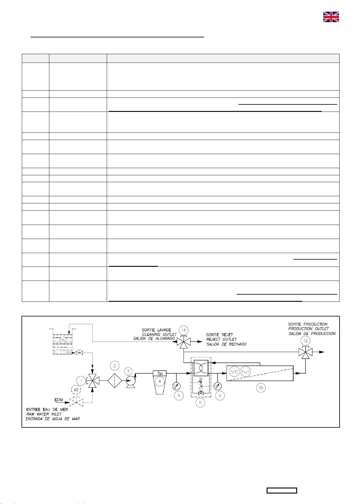
3. Position the inlet valve (1) so as to take water from the auxiliary tank (bucket) and direct it towards the LP pump.
4. Put the cleaning valve (11) in reject position.
5. Put the production valve (12) to reject position.
6. Put the unit ON by opening the main breaker on "ON" (1). Check the level of water in the auxiliary tank (or bucket).
7. Turn OFF the unit by closing the main breaker on "OFF" (0) before the auxiliary tank (or bucket) is empty to avoid air accumulation.
8. When pump is stopped, shut the hull valve (V0) and check valves position (initial position).
3.3 – STOPPING WITH PRESERVATION
BEFORE THE PRESERVATION PROCEDURE, DO A MEMBRANE RINSING (See 3.2)
Fresh water preservation requires the use of an auxiliary tank (or bucket), which should be perfectly clean and FREE OF ANY
TRACES OF GREASY SUBSTANCES. Preservation should imperatively be carried out before stopping the unit over a long period
(more than 2 weeks).
1. Use the preservation liquid (BIOCIDE) - reference AQUA-BASE, Ref. 752002-20.
2. Turn OFF the unit by closing the main breaker on "OFF" (0).
3. Take 10 liters of water from the principal tank, fill the auxiliary tank (bucket) and add the preservation liquid BIOCIDE: mix with the
water.
If the unit is to be stored at a temperature below 0°C, 20% of AQUA-BASE ANTI-FREEZE® ref.752004 must be added to the
preservation solution, during its preparation.
4. Position the inlet valve (1) so as to take water from the auxiliary tank (bucket) and direct it towards the LP pump.
5. Open the air bleed valve (7) of the hydraulic almplifier (6).
6. Put the cleaning valve (11) in reject position
7. Put the production valve (12) to reject position.
8. Put the unit ON by opening the main breaker on "ON" (1). Check the level of water in the auxiliary tank (or bucket).
9. Turn OFF the unit by closing the main breaker on "OFF" (0) before the auxiliary tank (or bucket) is empty to avoid air accumulation.
10. When pump is stopped, shut the hull valve (V0) and check valves position (initial position).
N.B : In order to avoid the PRESERVATION procedure during immobilisation of the unit, operate the unit for a few minutes every
week. It is strongly advised to carry out rinsing by fresh water every time the unit is stopped, as this guarantees the longevity of the
membrane and avoids oxidation of metal parts by electro corrosion.

\\Serveurslce3\DAO\Etude-3d\Aquaset\0-DOSSIER TECHNIQUES\1-sw-plaisance\ESW\09- Manuels Utilisateur\DOC UTILISATEUR ESB FRUKES 2012-11-K.doc VERSION 2012-11-K FR/UK/ES Page 21/39
3.4 – STOPPING WITH WINTERING PROCEDURE : CLEANING + PRESERVATION (LONG TIME STOP)
1. Use the AQUA-BASE wintering kit, which contains 1 cleaning solution + 1 preservation solution + filter 5µ.
2. Rinse the membranes with fresh water as described in chapter (See 3.2 previous page).
Cleaning
3. Fill the auxiliary tank (or bucket) with 10 litres of dechlorinated fresh water.
4. Prepare the cleaning solution 752003-MC11 (see 752037-EXP10) by mixing it in the auxiliary tank (or bucket).
5. Check the cleaning pipes connexions (B4) and (A3) in outlet/inlet of the auxiliary tank (or bucket) and open the cleaning valve (11)
to cleaning position.
6. Position the inlet valve (1) so as to take water from the auxiliary tank (bucket).
7. Open the air bleed valve (7) of the hydraulic amplifier (6).
8. Put the production valve (12) to reject position.
9. Put the unit ON by opening the main breaker on "ON" (1), operating in closed circuit.
10. Let the unit works in closed circuit for 20 minutes.
11. After this time, turn OFF the unit by closing the main breaker on "OFF" (0).
12. When the unit stops, empty the solution out of the auxiliary tank (or bucket) and clean it with fresh water.
13. Position the cleaning valve (11) in the reject position.
14. Rinse the membranes as described in chapter 3.2 previous page.
15. Take 10 liters of water from the principal tank, fill the auxiliary tank (bucket) (without chlorine because can damage the membrane).
16. Prepare the cleaning solution 752003-MC3 (see 752037-EXP10) by mixing it in the auxiliary tank (or bucket).
17. Open the cleaning valve (11) to cleaning position.
18. Put the unit ON by opening the main breaker on "ON" (1), operating in closed circuit.
19. Let the unit works in closed circuit for 20 minutes.
20. After this time, turn OFF the unit by closing the main breaker on "OFF" (0).
21. When the unit stops, empty the solution out of the auxiliary tank (or bucket) and clean it with fresh water.
22. Position the cleaning valve (11) in the reject position.
23. Rinse the membranes as described in chapter 3.2 previous page.
Preservation
24. Fill the auxiliary tank with 10 litres of fresh water and add the AQUA-BASE preservation solution BIOCIDE, Ref. 752002-20 and mix.
If the unit is to be stored at a temperature below 0°C, 20% of AQUA-BASE ANTI-FREEZE® ref.752004 must be added to the
preservation solution, during its preparation.
25. Position the inlet valve (1) so as to take water from the auxiliary tank (bucket) and direct it towards the LP pump.
26. Open the air bleed valve (7) of the hydraulic amplifier (6).
27. Position the cleaning valve (11) in the reject position.
28. Put the production valve (12) to reject position.
29. Put the unit ON by opening the main breaker on "ON" (1). Check the level of water in the auxiliary tank (or bucket).
30. Turn OFF the unit by closing the main breaker on "OFF" (0) before the auxiliary tank (or bucket) is empty to avoid air accumulation.
31. When pump is stopped, shut the hull valve (V0) and check valves position (initial position).
32. Whatever their condition, empty the filter (4) to avoid any bacteriological proliferation and if needs be, replace the filtration cartridge
(If you put the old cartridge back, wait until they are dry).
33. It is necessary that water remains in the membrane, make sure it cannot freeze (in the case of a possible risk, add to the storage
solution, the anti-freeze solution Ref. 752004 ( See chapter 3.3 previous page).
If the unit is to be stored at a temperature below 0°C, 20% of AQUA-BASE ANTI-FREEZE® ref.752004 must be added
to the preservation solution, during its preparation.
NB : PRESERVATION OF THE PROCON PUMP : It is necessary to preserve the PROCON pump (with glycerine), for this, refer to the
Technical Note NT0809 (at the end of the technical handbook).

\\Serveurslce3\DAO\Etude-3d\Aquaset\0-DOSSIER TECHNIQUES\1-sw-plaisance\ESW\09- Manuels Utilisateur\DOC UTILISATEUR ESB FRUKES 2012-11-K.doc VERSION 2012-11-K FR/UK/ES Page 22/39
D – WATERMAKER MAINTENANCE
The AQUA-BASE unit must be regularly maintained in order to avoid the occurrence of defects, which could affect its efficiency, its operation
and its reliability. The intervals between maintenance of the AQUA-BASE unit depend on the frequency and conditions of use.
1 – MAINTENANCE SCHEDULE
OPERATION FREQUENCY NECESSARY SPARE
PARTS
Minimum
Replacement of filter cartridge When it is clogged and at wintering 1 / year 711019
Cleaning the prime filter When it is clogged 1 / week
Cleaning the membrane Each year at wintering 1 / year 752037-EXP10
On this basis the user will adapt his own maintenance schedule, which will depend on his personal use of the unit.
2 – SPARE PARTS FOR ONE YEAR
The spare parts set, for one year AQUA-BASE, Ref 752054, contains all the necessary parts for servicing the AQUA-BASE desalination unit.
QTE/QTY REFERENCE DESCRIPTION
4 711019 Filter element 5µ-10’’
1 752037-EXP10 MC11 Alkaline cleaner & MC3 Acid cleaner
2 752002-20 Storage solution
3 – REPLACEMENT OF THE FILTER CARTRIDGE (Unit stopped)
1. Turn OFF the unit by closing the main breaker on "OFF" (0).
2. Close the hull valve (V0).
3. Open the filter by unscrewing the tightening nut using the filter spanner.
4. Free the used cartridges by setting down the filter bowl.
5. Replace the used cartridges with a genuine new one (green colour).
6. Wipe and lightly oil the seal with food fat.
7. Reset the filter after having checked the cartridge position.
8. Screw the tightening nut by hand.
4 – CLEANING OF THE MEMBRANE
When should the membrane be cleaned?
Cleaning of the membrane is necessary once a year (see chapter D : Maintenance schedule)
In normal operation, the R/O membrane can be clogged by mineral and organic deposits, which accumulate until they cause a drop in fresh
water production quality and quantity. The membrane should be cleaned each time the quantity or the quality of the produced water changes
excessively. Before proceeding with membrane cleaning check that the change in performance has no other cause, such as:
- Low seawater temperature,
- Filter clogged, water system badly drained, leading to lack of water at the pump,
- Inefficient operation of the HP pump: leaks, wear,...
Cleaning of the membrane can only be carried out when it’s inside the pressure vessel. Never take a membrane out of its
pressure vessel.
How should the membrane be cleaned?
Î
See the 3.4 – Wintering procedure « Cleaning »
In case of long term wintering, proceed with preservation operation.
NOTA : Membrane cleaning can be done in the factory or by your agent in a more thorough way, on a specialised bench. Contact
your agent or the factory directly.
When should the membrane be replaced?
A membrane has a lifetime of about 5 years. Then, as the plastic materials harden, the pores retighten and production will decrease. Then,
you must replace the membrane. If the membrane has accidentally taken in fuel or oil, it must be replaced. The membrane is one of the more
fragile elements of the watermaker, it is necessary to take care of them by respecting the maintenance requirements.
To replace a reverse osmosis membrane, please contact us directly or through one of our dealers, to obtain the membrane replacement
specification sheet, by telling us the serial number of the membrane.

\\Serveurslce3\DAO\Etude-3d\Aquaset\0-DOSSIER TECHNIQUES\1-sw-plaisance\ESW\09- Manuels Utilisateur\DOC UTILISATEUR ESB FRUKES 2012-11-K.doc VERSION 2012-11-K FR/UK/ES Page 33/39
E – ANNEXES/APPENDIX/ANEXOS
RAPPORT DE MISE EN SERVICE/ START-UP REPORT / INFORME DE PUESTA EN SERVICIO
ATTENTION : Ce RAPPORT doit être complété après la mise en
service de l’appareil AQUA-BASE, puis retourné à l’usine à
l’adresse suivante :
WARNING: This REPORT should be completed after starting up of
the
AQUA-BASE
unit, then returned to the factory at the following
address:
ATENCIÓN: Este INFORME se debe cumplimentar debidamente
después de la puesta en marcha del AQUA-BASE y enviar al
fabricante a la dirección siguiente:
SLCE
SERVICE TECHNIQUE
149 RUE SALVADOR DALI
CS8002 CAUDAN – 56607 LANESTER CEDEX - FRANCE
LE NON-RETOUR EN USINE DE CE RAPPORT COMPLETE,
DATE ET SIGNE, SUSPENDRAIT L’APPLICATION DE LA
GARANTIE.
IF THIS REPORT, COMPLETED, DATED AND SIGNED, IS NOT
RETURNED TO THE FACTORY, THE GUARANTEE WILL BE
SUSPENDED.
LA NO-DEVOLUCIÓN DE ESTE INFORME DEBIDAMENTE
CUMPLIMENTADO, CON FECHA Y FIRMA ANULARÍA LA
APLICACIÓN DE LA GARANTIA
AQU
A
-BASE
Type /
T
ype / Tipo
N° de série
Series N°
N° de série
Tension
Voltage
Voltaje V
Options
Options
Opciones
Client
Client
Cliente
Utilisateur
User
Usuario
Type & Nom du bateau
Type & Name of the boat
Tipo y nombre de la embarcación
Contrôle circuits BP
LP circuits control
Control circuito BP
Fonctionnement Vanne de Rinçage
Rinsing valve operating
Funcionamiento válvula de aclarado
Pression
Pressure
Presión bar
Options
Extras
Opciones
Options
Extras
Opciones
VISA
TECHNICIEN
VISA
TECHNICIAN
VISA TÉCNICO
CONTROLE SLCE
Date / Date / Fecha
Lieu / Place / Sitio
Agent / Agent / Agente
Technicien / Technician /
Técnico
ALIMENTATION ELECTRIQUE / ELECTRIC SUPPLY / ALIMENTACIÓN ELÉCTRICA
Capacity of the batteries
Capacidad de las baterías
Ah
Intensity supplied by the
generator
Intensidad generador
A
EAU DE MER / SEAWATER / AGUA DE MAR
Salinité mesurée
Measured salinity
Salinidad medida
mg/l
Température
Temperature
Temperatura
°C
EAU PRODUITE / WATER PRODUCED / AGUA PRODUCIDA
Salinité mesurée
Measured salinity
Salinidad medida
mg/l
Débit mesuré
Measured product flow
Caudal medido
l/h


\\Serveurslce3\DAO\Etude-3d\Aquaset\0-DOSSIER TECHNIQUES\1-sw-plaisance\ESW\09- Manuels Utilisateur\DOC UTILISATEUR ESB FRUKES 2012-11-K.doc VERSION 2012-11-K FR/UK/ES Page 35/39
PIECES DE RECHANGE / SPARE PARTS / PIEZAS DE RECAMBIOS
Rep Re
f
Designation Description
Descripción Modèle
1 & 11 711040 VANNE MANUELLE 3 X F3/4" RX 3 X F3/4" MANUAL VALVE RX VÁLVULA 3 VIAS 3F3/4" RX
2 711075 FILTRE CREPINE PP MM 3/4" 400µ PLASTIC COARSE STRAINER MM3/4" 400μFILTRO DESAGUE PLAST MM3/4" 400µ
3
605031 POMPE BP 330L ESW30 LP PUMP 330L ESW30 BOMBA BP 330L ESW30 30L/H
656200-90 MOTEUR CC 12V 125W 1650 tr/mn MOTOR 12VDC 125W 1650 tr/mn MOTOR 12VCC 125W 1650 tr/mn 30L/H
656224-90 MOTEUR CC 24V 150W 1700 tr/mn MOTOR 24VDC 150W 1700 tr/mn MOTOR 24VCC 150W 1700 tr/mn 30L/H
605032 POMPE BP 660L ESW60 LP PUMP 660L ESW60 BOMBA BP 660L ESW60 60L/H
6-56.202-90 MOTEUR 12V 460W 1650 tr/mn MOTOR 12VDC 460W 1650 tr/mn MOTOR 12VCC 460W 1650 tr/mn 60L/H
6-56.203-90 MOTEUR 24V 550W 1650 tr/mn MOTOR 24VDC 550W 1650 tr/mn MOTOR 24VCC 550W 1650 tr/mn 60L/H
605031-10 KIT REPARATION POMPE 330L/H REPAIR KIT PUMP 330L/H KIT DE REPARACIÓN BOMBA 330L / H 30L/H
605032-10 KIT REPARATION POMPE 660L/H REPAIR KIT PUMP 660L/H KIT DE REPARACIÓN BOMBA 660L / H 60L/H
4 710010-03 JOINT TOR. 91,44x5,33 NBR70SH SEAL 91,44x5,33 NBR70SH JUNTA TOR. 91,44x5,33 NBR70SH
711024 FILTRE 10" FF3/4 PN8 10” FILTER FF3/4PN8 FILTRO 10" FF3/4 PN8
711019 CARTOUCHE 10"- 5 MICRONS 10"- 5 MICRONS FILTER ELEMENT CARTUCHO 10" 5µ
5 610022 MANO 0-16 B.M1/4G Ø40 HP GAUGE 0-16B 1/4G Ø40 MANO 0-16B M1/4G Ø40
6 110121-40 S/E ESW AQ-B RECUPERATEUR D’ENERGIE S/E ESW ENERGY RECOVERY S/E ESW AQ-B AMPLIFICADOR DE PRESION
110121-10 KIT JOINTS ET BAGUES ESW O-RING KIT ESW KIT DE JUNTA ESW
110121-11 KIT REPARATION DISTRIBUTEUR ESW DISTRIBUTOR REPAIR KIT ESB/ESW KIT DE REPARACIÓN AMPLIFICADOR ESW
710018-82 KIT CLAPETS ESW VALVES KIT ESW KIT VÁLVULA DE COMPROBACION ESW
7 719201 VANNE ARRET INOX FF 1/4"G SHUT-OFF VALVE SS316 FF1/4"G VÁLVULA FF 1/4" G
718092 DROIT INOX MM 1/4" GAZ SS STRAIGHT MM 1/4" GAZ ACERO DERECHO INOXIDABLE MM 1/4 " GAS
9 610023 MANO 0-100B M1/4G Ø40 INOX HP GAUGE 0-100B 1/4G Ø40 INOX MANO 0-100B M1/4G Ø40 INOX
10 711205 MEMBRANE 4"-21 SW 4"-21 SW R/O MEMBRANE MEMBRANA 4"-21 SW
11 711040 VANNE MANUELLE 3 VOIES F3/4" RX 3 X F3/4" MANUAL VALVE RX VALVULA 3 VIAS F3/4” RX
12 719318-01 VANNE 3 VOIES 3xF 1/4 3-WAY VALVE 3x1/4" VALVULA 3 VÍAS
722062 DISJONCTEUR CC 20A UNI MAINS SWITCH DC 20A UNI DISYUNTOR 20A UNI 30L/H 12VCC
722064 DISJONCTEUR CC 40A UNI MAINS SWITCH DC 40A DISYUNTOR 40A 60L/H 12VCC
722068 DISJONCTEUR CC 8A UNI MAINS SWITCH DC 8A DISYUNTOR 8A 30L/H 24VCC
722063 DISJONCTEUR CC 30A UNI MAINS SWITCH DC 30A DISYUNTOR 30A 60L/H 24VCC
880050 COFFRET ELECTRIQUE ESB301 12V ESB301 CONTROL BOX 12VDC CUADRO DE MANDO ESB301 12VCC 30L/H 12VCC
880051 COFFRET ELECTRIQUE ESB302 24V ESB302 CONTROL BOX 24VDC CUADRO DE MANDO ESB302 24VCC 30L/H 24VCC
880052 COFFRET ELECTRIQUE ESB601 12V ESB601 CONTROL BOX 12VDC CUADRO DE MANDO ESB601 12VCC 60L/H 12VCC
880053 COFFRET ELECTRIQUE ESB602 24V ESB602 CONTROL BOX 24VDC CUADRO DE MANDO ESB602 24VCC 60L/H 24VCC
825953 OPTION ALIM BITENSION 230-12 25A EXTRA CONTROL BOX 230-12 25A OPCIÓN CUADRO DE MANDO 230-12 25A ESB301
825954 OPTION ALIM BITENSION 230-12 60A EXTRA CONTROL BOX 230-12 60A OPCIÓN CUADRO DE MANDO 230-12 60A ESB601
825955 OPTION ALIM BITENSION 230-24 12A EXTRA CONTROL BOX 230-24 12A OPCIÓN CUADRO DE MANDO 230-24 12A ESB302
825956 OPTION ALIM BITENSION 230-24 30A EXTRA CONTROL BOX 230-24 30A OPCIÓN CUADRO DE MANDO 230-24 30A ESB602

\\Serveurslce3\DAO\Etude-3d\Aquaset\0-DOSSIER TECHNIQUES\1-sw-plaisance\ESW\09- Manuels Utilisateur\DOC UTILISATEUR ESB FRUKES 2012-11-K.doc VERSION 2012-11-K FR/UK/ES Page 36/39
DIMENSIONS / DIMENSIONS / DIMENSIONES
FILTRE A CARTOUCHE / CARTRIDGE
FILTER / CARTUCHO DE FILTRO
CREPINE / STRAINER / FILTRO
POMPE DE GAVAGE / BOOSTER PUMP / BOMBA BP
Pompe / Pump / Bomba
:
30/6
0
/9
0
L/H
COFFRET ELECTRIQUE / CONTROL
BOX / CUADTRO DE MANDO

\\Serveurslce3\DAO\Etude-3d\Aquaset\0-DOSSIER TECHNIQUES\1-sw-plaisance\ESW\09- Manuels Utilisateur\DOC UTILISATEUR ESB FRUKES 2012-11-K.doc VERSION 2012-11-K FR/UK/ES Page 37/39
INSTALLATION A BORD / INSTALLATION ON BOARD / INSTALACION

\\Serveurslce3\DAO\Etude-3d\Aquaset\0-DOSSIER TECHNIQUES\1-sw-plaisance\ESW\09- Manuels Utilisateur\DOC UTILISATEUR ESB FRUKES 2012-11-K.doc VERSION 2012-11-K FR/UK/ES Page 38/39
STOCKAGE POMPE / PRESERVATION PUMP / MANTENIMIENTO DE LA BOMBA

\\Serveurslce3\DAO\Etude-3d\Aquaset\0-DOSSIER TECHNIQUES\1-sw-plaisance\ESW\09- Manuels Utilisateur\DOC UTILISATEUR ESB FRUKES 2012-11-K.doc VERSION 2012-11-K FR/UK/ES Page 39/39
LE SERVICE
AQUA-BASE
SLCE – 149 RUE SALVADOR DALI – ZA DE KERGOUARAN –
CS8002 CAUDAN – 56607 LANESTER CEDEX – France –
TEL : +33 (0) 297.838.888 FAX : +33 (0) 297.838.333
CONTACT YOUR DEALER/AGENT:
CONTACTA SU AGENTE:
Other manuals for ESB Series
1
This manual suits for next models
4
Table of contents
Other Aqua-Base Marine Equipment manuals
Popular Marine Equipment manuals by other brands

Nera
Nera Saturn BM Marine Operator's manual

Argonaut
Argonaut M7 Installation and operation guide

Garmin
Garmin GPSMAP 168 Sounder Owner's manual and reference guide

Kongsberg
Kongsberg M3 Sonar quick start

Hi-Target GPS
Hi-Target GPS HI-TARGET HD-MAX user guide

Kongsberg
Kongsberg Simrad SU90 Series Technical specifications