Aqua-Marina BT-UD250 User manual

INFLATABLE
AIR-DECK SPORT BOATS
User’s Guide
BT-UD250 / BT-UD298 / BT-UD350
www.aquamarina.com

2
THANK YOU FOR CHOOSING AQUA MARINA
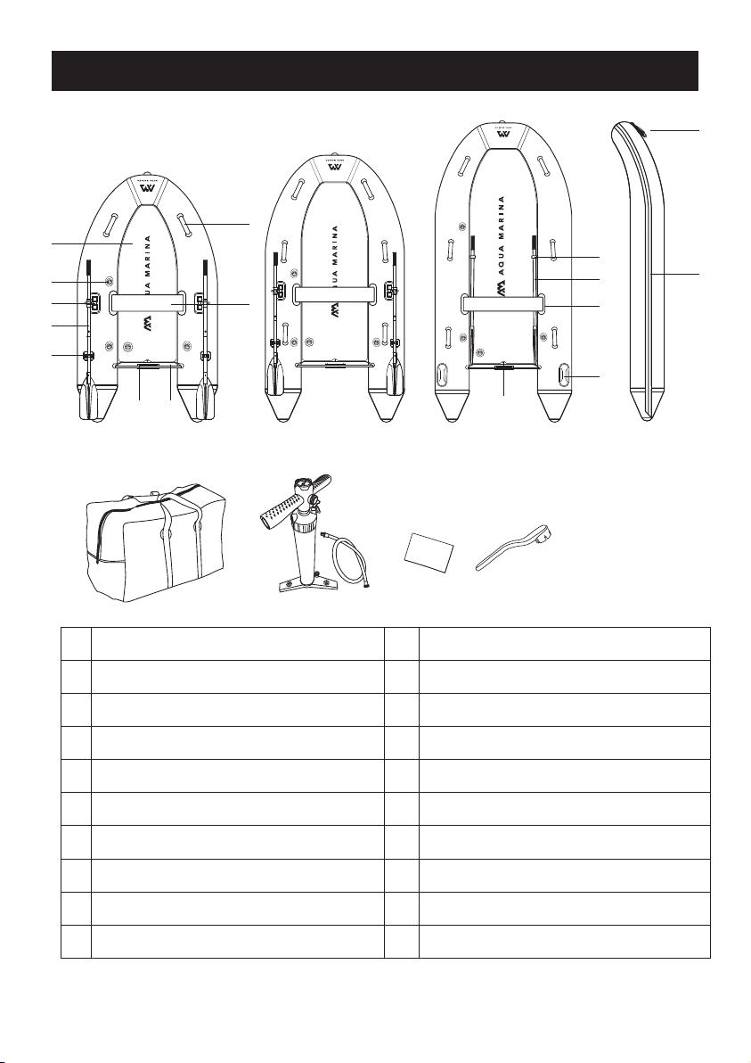
DELUXE SPORT BOATS
Compact and lightweight, these economical inflatable boats are great ship to shore
tender crafts or a highly portable pleasure boat for the boater on the go. Bring your
roll-up boat with you to the lake, the beach or wherever! With a set-up time of just
minutes, no trailers and no special equipment, these boats will allow easy access to
some of those places you've only seen from the shore.
This manual has been compiled to help you achieve long term safe use and pleasure
from your Aqua Marina® boats.
GENERAL INFORMATION
SAFETY
In a manual of this type it is impossible to give adequate space to the topic of water
safety. Check in your local area for information and/or training as needed. Inform
yourself about local regulations and dangers related to boating and/or other water
activities. It is your responsibility to be aware of and comply with all relevant safety
regulations. For all water recreation or sport you should have a reasonable swimming
ability. Just as swimmers have a cardinal rule about not swimming alone. It is strongly
advised that you should never go boating alone.
PLEASE KEEP THIS MANUAL IN A SECURE PLACE, AND HAND IT OVER TO THE NEW
OWNER WHEN YOU SELL THE CRAFT. RECORD THE "HULL IDENTIFICATION
NUMBER" (HIN) WHICH IS LABELLED ON THE BOAT
MANUFACTURER’S CERTIFICATION
Our boats comply with the ISO 6185 standard
established by the International Organization
for Standardization.
MANUFACTURER’S RECOMMENDATION
The total number of persons, motor power
and total weight shall not exceed the limits
labeled (Fig. 1) on the boat.
S/N
STANDARD EN ISO 6185-2:2018
DESIGN CATEGORY C
BOAT TYPE TYPE V
ORIENTAL RECREATIONAL PRODUCTS (SHANGHAI) CO., LTD
NO. 1699 Da Ye Road, Fengxian, Shanghai, China
WWW.AQUAMARINA.COM MADE IN CHINA
BOAT MODEL BT-UD298
=
11.03
kw
15
HP
=
3
=
1
=
360 kg (792 lbs)
=
0.25 bar (3.62 psi)
1 bar (15 psi) (DECK)
S/N
CN-ORP
DATE
N.W
28 kg (61.7 lbs)
+ +
Fig.1
1
2
3
4
5
6
7
Label format for boat

3
SAFETY CHECK LIST & SAFETY WARNING
• Always wear an approved Personal Flotation Device (Life Preserver).
• Be aware of your local boating rules and regulations and abide by them accordingly.
• Check inflation levels each time before you go out and inflate your boat for a full 24
hours before undertaking long trips.
• DO NOT allow children to use Aqua Marina unsupervised.
• DO NOT consume alcohol while boating or operating a boat while under the
influence of alcohol or drugs.
• DO NOT drag your Aqua Marina over rocks or gravel if it can be avoided.
• DO NOT exceed the certified maximum capacities of this boat under any
circumstance.
• DO NOT go boating alone.
• DO NOT use compressors, co² or compressed air for inflation, only use Aqua Marina
recommended pumps.
• DO NOT use your Aqua Marina Boat as a personal flotation device as they are
designed for leisure/recreation in mind.
• DO NOT sleep inside of your Aqua Marina while on the water.
BT-
UD250
BT-
UD298
BT-
UD350
CategoryModel
D
C
C
Item size
8’2”x55”
(2.5×1.4m)
9’9”x61”
(2.98×1.55m)
11’6”x63”
(3.5×1.6m)
Max. Air
pressure
0.25bar/3.62psi
Hull
1bar/15psi
Floor
0.25bar/3.62psi
Hull
1bar/15psi
Floor
0.25bar/3.62psi
Hull
1bar/15psi
Floor
No. of air
chamber
3+1
3+1
3+1
Max.
Passenger
2+1
3+1
5
Max.
Payload
280 kg
(616 lbs)
360 kg
(792 lbs)
480 kg
(1056 lbs)
Max. Motor
Power
5HP/
3.7KW
15HP/
11.03KW
20HP/
14.7KW
Net
weight
25 kg
(55.1 lbs)
28 kg
(61.7 lbs)
34 kg
(75 lbs)
1. As per Directive 2013/53/EU boat Design Category C - Inshore: Designed for
voyages in coastal waters,large bays, estuaries, lakes and rivers where conditionsup
to, and including, wind force 6 and significant wave heights up to, and including, 2m
may be experienced.
2. Maximum person’s capacity without console
3. Manufacturer’s recommended maximum load capacity
4. Maximum motor power
5. Manufacturer’s recommended working pressure
6. Hull identification number (HIN)
7. Net weight
INFLATABLE BOAT SPECS & FEATURES
SPECIFICATIONS

4
1
BT-UD250 BT-UD298 BT-UD350
1
2
3
4
5
6
7
8
9
10
11
12
13
14
15
16
17
18
19
DWF air deck floor
Transom (Height15”/38.1cm)
Seat connector
Rotation oarlock (except BT-UD350)
Wooden bench seat
Oar holder (except BT-UD350)
D-ring & towing rope
Aluminum oar
Anti-collision rubber strake
High pressure recessed valve
Engine mount
Safety grab handle
Velcro oar holder (only for BT-UD350)
PVC lift handle (only for BT-UD350)
NOTE: Drawings and pictures for illustration purpose only. Actual product may vary.
Not to scale.
PART LIST
2
6
9
10
3
5
16
4
7 158
4
12
14
11
13
17
18 19
Double-action pump, Inflation hose
Repair patch
Carry bag
Drain valve
Wrench

5
INSTRUCTION FOR ASSEMBLING
AND DISASSEMBLING
Pump Set Up And Inflation
B
A
C
1. Open the valve cap by twisting counter-clockwise. Ensure the valve is
clear from debris, sand, or dirt before releasing.
2. Push valve button in and turn counter-clockwise 90 degrees so it pops up
and is in the “OUT” position.
3. Insert the pump hose and twist it 45 degree clockwise to lock in place.
Inflate until you reach the required pressure.
Connect the pump hose to the
gauge housing and secure it tightly.
①①
UNFOLD THE BOAT
Clear a clean and flat space
that is free of any sharp
objects and unroll the boat
hull so that it is laid out flat.

6
Over inflation will void your warranty. 12PSI
minimum for proper inflatable deck floor
operation and 15PSI maximum.
D
1. Use DOUBLE ACTION mode by closing the air-tap to pump the boat
hull up to 0.25 bar/ 3.62 psi, and the deck floor up to 0.5 bar/ 7 psi.
2. Switch to SINGLE ACTION position by opening the air-tap to pump the
deck floor up to 1 bar/ 15 psi.
Inflate Faster With Less Effort
•Use full range of the pump cylinder
while keeping your arms extended.
•Bend your knees and use the body
weight.
DOUBLE
ACTION
SINGLE
ACTION
• Electric Pumps can be used to inflate boat up to 80-90%. However, the
remaining pressure required should be achieved by using the hand
pump to avoid over-inflation.
• Do not use air compressors as this voids warranty of boat.
• Before long trips, ensure the boat has been inflated and has maintained
pressure for a minimum of 24 hours.
PRECAUTION & TIPS
The pump can be switched between double action mode and single
action mode.
LIQUID AIR V1

7
E
INFLATE THE BOAT
1. Inflate the tube chambers until the surface is free of wrinkles. By partially
inflating the boat, the floor and the bench seat will be easier to install.
2. Place the DWF air deck floor inside of the boat with the air valve facing up.
3. Start to install the wooden bench seat. Slide the bench seat into the position by
inserting the flaps on both chambers of the boat into notches on the seat board.
Please note the second bench seat is sold separately.
4. With the floor installed and the seat in place, you are now ready to fully inflate
the floor up to the maximum air pressure (1 bar/ 15 psi). Then, fully inflate the
tube chambers up to the maximum air pressure (0.25 bar/ 3.62 psi).
Step 1
Step 1
Step 1
(1) (2)
(3)
Step 3
Step 3 Step 2 Step 3
(4) (5)
HIGH PRESSURE
VALVE

8
5. Insert the plug into the drain valve beneath the transom.
IMPORTANT!
Make sure that the drain valve is always in the closed position as shown in picture
(5) while on the water. When you are motoring is the only time that the drain valve
can be in the opened position.
NOTES: Always check the inflation pressure before using the boat. Air temperature
and weather conditions do affect the internal air pressure of inflatable products. In
cold weather the product will lose some pressure due to the fact that the air will
contract. If this occurs, you may want to add a little air to the product. However, in
hot weather, the air will expand. In this case, you must let some air out to protect
the product from overpressure.
• Only use Aqua Marina® approved inflation pumps.
• Under and over-inflation will result in safety hazards.
• Never stand on or rest objects on the boat during inflation.
• Never open the cap of air valve while the boat is in use.
• Be sure the valve is tightly closed before using the boat.
Before deflation, please keep in mind that you should not fully deflate one
chamber while other chambers remain fully inflated as this can cause damage to
the bulkheads of your boat.
1. Clear any water or debris out of the valve areas.
2. HIGH PRESSURE VALVE
Open the valve cap first. Slowly press down on the valve stem to start letting air
out of the boat. There will be an initial burst of air, but that will slow down very
quickly. Once the air flow has slowed down, press the valve stem all the way
down and turn it clockwise to lock it into the “OPEN” position.
3. Open all air valves including the tube chambers and the DWF air deck floor.
Release around 50-75% of the air from each chamber before fully deflating.
Excess air can be pushed out as you roll up the boat.
F
HIGH PRESSURE VALVE
BOAT DEFLATION

9
1. Remove all the accessories from the boat: oars, wooden seat and the DWF air
deck floor.
NOTE: Remember to remove the DWF air deck floor before folding.
2. Fold the end of the tube chambers towards the transom.
3. Roll the boat towards the bow, pushing out any remaining air as you go. Then
have one fold from the bow and tuck the bow neatly underneath.
4. For the DWF air deck floor, make the first fold from the front. Continue folding
towards the valves tightly, pushing out any remaining air as you go.
5. The boat storage bag is designed to allow you to get your boat into the bag as
easily as possible with minimal folds.
G
BOAT FOLDING STEPS
(1)
(2) (3)
(4) (5)
NOTE: Remember to remove
the DWF air deck floor before folding.

10
2. OUTBOARD MOTOR INSTALLATION
After the boat is fully inflated and well assembled, attach your outboard motor onto the
Engine Mount at the center of the transom.
NOTE:
•Ensure the motor is always fixed on the transom.
• Read the instruction manual of the outboard motor for correct installation and operation.
WARNING:
Overpowering a boat can result in serious injury, death or boat damage. Do not exceed the
maximum motor power.
ACCESSORY ASSEMBLY
1) Join the two shafts of the oars by snapping them together.
2) There are pre-drilled holes in the middle of the oars so you can slide it over the oar
holder and then secure the oar in place by using the rotation oarlock.
NOTE: When the oars are not in use, leave the oars in the oar holders to avoid
damage and loss.
1. OAR ASSEMBLY
(1)
(2)

11
The boat is made of the high quality materials and complies with ISO 6185 standards.
Altering the construction of the boat will endanger your own safety, safety of the
occupants and void the limited warranty!
There is very little that you have to do to keep your boat in good condition for many
years.
• When landing on the shore, carry the boat. Do not tow it on the sand or ground as
damage may occur.
• If you use the towing D-ring to tow the boat, go slowly to avoid over-towing as
damage may occur.
• Clean your boat after a trip to prevent damage from sand, salt water or sun exposure.
Most dirt can be removed with a garden hose, a sponge and mild soap.
• Make sure the boat is completely dry before storing, and remove any excess moisture
that could cause unsightly mildew. Use as few cleaning agents as possible, do not
discharge waste agents into water, and clean your boat preferably on land.
• Choose a cool and dry spot to store the boat. Ensure protection against rodents and
other vermin, as they feed on the fabric of the boat.
• The boat may be stored inflated, but do not place any heavy or sharp objects on it.
Hanging the boat is not recommended.
• If you’re planning to leave your boat outside, make sure to keep it raised up off the
ground. It is also a good idea to keep it covered so that it is not directly exposed to
berries, leaves, rain, sunlight and other elements. Boats that are left in water should
be emptied from time to time.
• Store the product and accessories in a dry place, with temperature controlled
between 32 degrees Fahrenheit (0 degrees Celsius) and 104 degrees Fahrenheit (40
degrees Celsius).
PRODUCT CARE AND STORAGE

12
AIR LEAK DETECTION
If your boat appears a bit soft, it might not be because of a leak. If the boat was inflated
late in the day with 32°C (90°F) air, that air might cool down to 25°C (77°F) overnight.
The cooler air exerts less pressure on the hull, so it could appear soft the next morning.
If there has been no temperature variation, you need to start looking for a leak:
• Take a good look at your boat from just a few feet away. Flip it over and closely check
over the outside. Any large leaks should be clearly visible.
• If you have an idea where your leak is, use a mix of dishwashing liquid and water in a
spray bottle, and spray over the suspicious areas. Any leak will produce bubbles that
will pinpoint the location of the leak.
• Check valves for leak, if necessary, spray soapy water around the valve and the valve
base.
LEAK DETECTION AND REPAIR
SMALL REPAIRS
1. Thoroughly clean and dry the damaged area. Completely deflate the product.
2. Cut a portion of the patch to cover the puncture and allow an additional 1/4” on
all sides. Always cut a round patch, never leave square corners.
3. Be sure the repair area is completely dry.
4. Apply generous coat glue to the vinyl repair patch and to the product.
5. Allow the glue to dry for 2 to 3 minutes, or until the glue becomes tacky.
6. Apply the patch to the product, using your thumb or finger; apply even pressure
across the entire surface of the patch. Make sure the edges of the patch are
pressed down along the entire diameter.
7. Allow the product to dry for at least 12 hours before inflating and using.
If there are large tears/cracks, please bring the water craft or any essential equipment
part into a professional repair shop for appropriate repair or replacement.
Inadvertent punctures can be repaired using included vinyl repair patch and vinyl glue.
You can also purchase additional PVC or silicon based glue for repairing camping mats,
tents or shoes from your local market to patch your boat. Please refer to the instruction
of the glue for patching.

13
HOW TO FIX A LEAKING VALVE
open
close
open
close
1. Inflate your DWF air deck floor up to the max
air pressure.
2. Stick your valve wrench down inside of valve
and turn clockwise to tighten the valve back
down onto the DWF air deck floor.
1. Completely deflate your DWF air deck floor.
2. Undo the dust cap and insert the valve wrench into the valve and twist counterclockwise
to remove the valve.
A. Try to tighten the valve
B. Re-install or replace a valve
3. Check the rubber ring to make sure that it is in the correct position, tight around the
valve and there is no debris in the way.
4. Be sure the pin spring is functioning properly and there are no cracks along the edges.
Rubber Ring

14
NOTE: Correctly use the wrench by pressing it with
one hand on top.
open
close
5. Ensure there are no strings from the drop stitching material.
6. Note the bottom piece of the valve is not attached to anything.
7. Fit the valve back into your DWF air deck floor.
8. Align all the threads and twist to tighten.
9. Once the valve is hand tight, use the valve wrench to seal completely.

15
WARRANTY
This product is designed in accordance with standards
for a specific use. Any modifications or transformations
higher than that indicated by the manufacturer could
result in serious risks for the user and will void the
warranty.
AM warrants this product to be free from major defects in material or workmanship
to the original purchaser for a period of ONE (1) Year from the date of purchase.
This warranty is subject to the following limitations:
1. The warranty is valid only when this product is used for normal recreational activities
and does not cover products used in rental or school operations.
2. AM will make the final warranty determination, which may require inspection and/or
photos of the equipment, which clearly show the defect(s). If necessary, this
information must be sent to the AM distributor in your country with prepaid postage.
Product can be returned only if a return authorization number is given in advance by
the AM distributor. The return authorization number must be clearly labeled on the
outside of the package, or it will be refused.
3. If a product is deemed to have manufacturing defect, the warranty covers the repair
or replacement of the defective product only. AM will not be responsible for any
costs, losses, or damages incurred as a result of loss or use of this product.
4. This warranty does not cover damage caused by misuse, abuse, neglect, normal
wear and tear including, but not limited to, punctures, damage due to excessive
heat exposure, damage caused by improper handling and storage, damage
caused by use in waves or shore break, boat breakage caused by filling or crashing
in surf conditions, or damage caused by anything other than defects in material and
workmanship.
5. This product must not be used in excess of the manufacturers recommended
maximum load capacity.
6. This warranty is void if any unauthorized repair, change or modification has been
made to any part of the equipment.
7. The warranty for any repaired or replacement equipment is good from the date of
the original purchase only.
8. The original purchase receipt must accompany all warranty claims. The name of the
retailer and date of purchase must be clear and legible.
9. There are no warranties that extend beyond the warranty specified here in.
WARNING
This manual suits for next models
2
Table of contents
Other Aqua-Marina Boat manuals

Aqua-Marina
Aqua-Marina Motion User manual

Aqua-Marina
Aqua-Marina TOMAHAWK User manual

Aqua-Marina
Aqua-Marina BETTA BE-312 User manual

Aqua-Marina
Aqua-Marina LAXO User manual

Aqua-Marina
Aqua-Marina BT-88890 User manual

Aqua-Marina
Aqua-Marina BT-AC285 User manual

Aqua-Marina
Aqua-Marina CASCADE BT-21CAP User manual

Aqua-Marina
Aqua-Marina BT-88810 User manual

Aqua-Marina
Aqua-Marina BETTA BE-312 User manual

Aqua-Marina
Aqua-Marina BT-88890 User manual