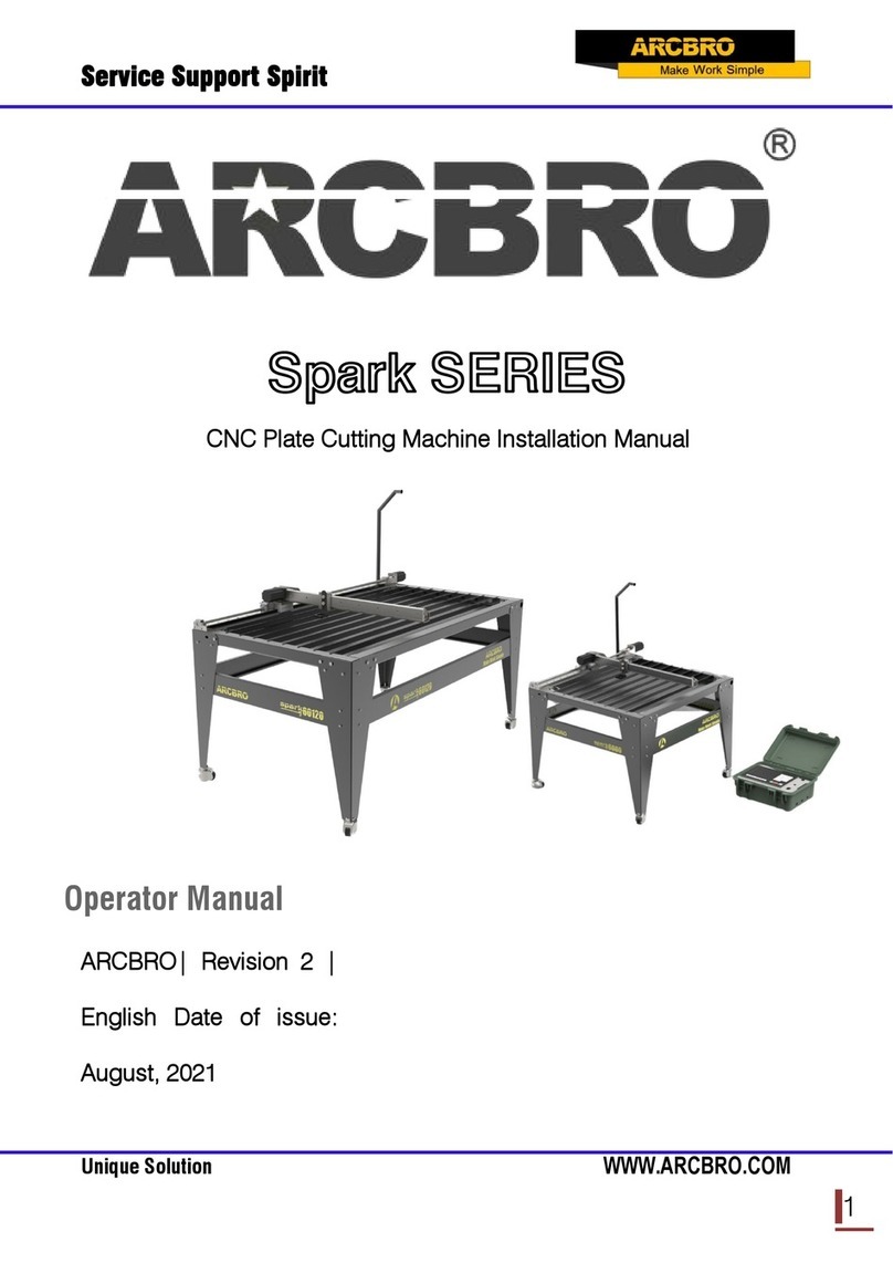
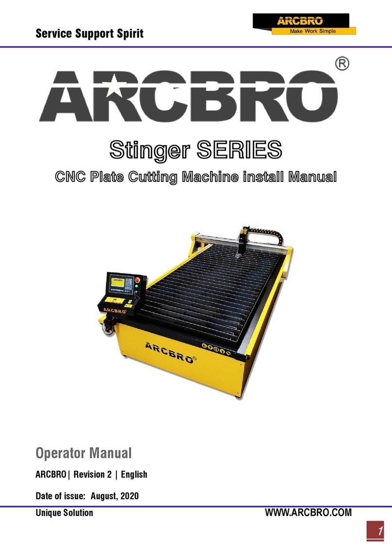
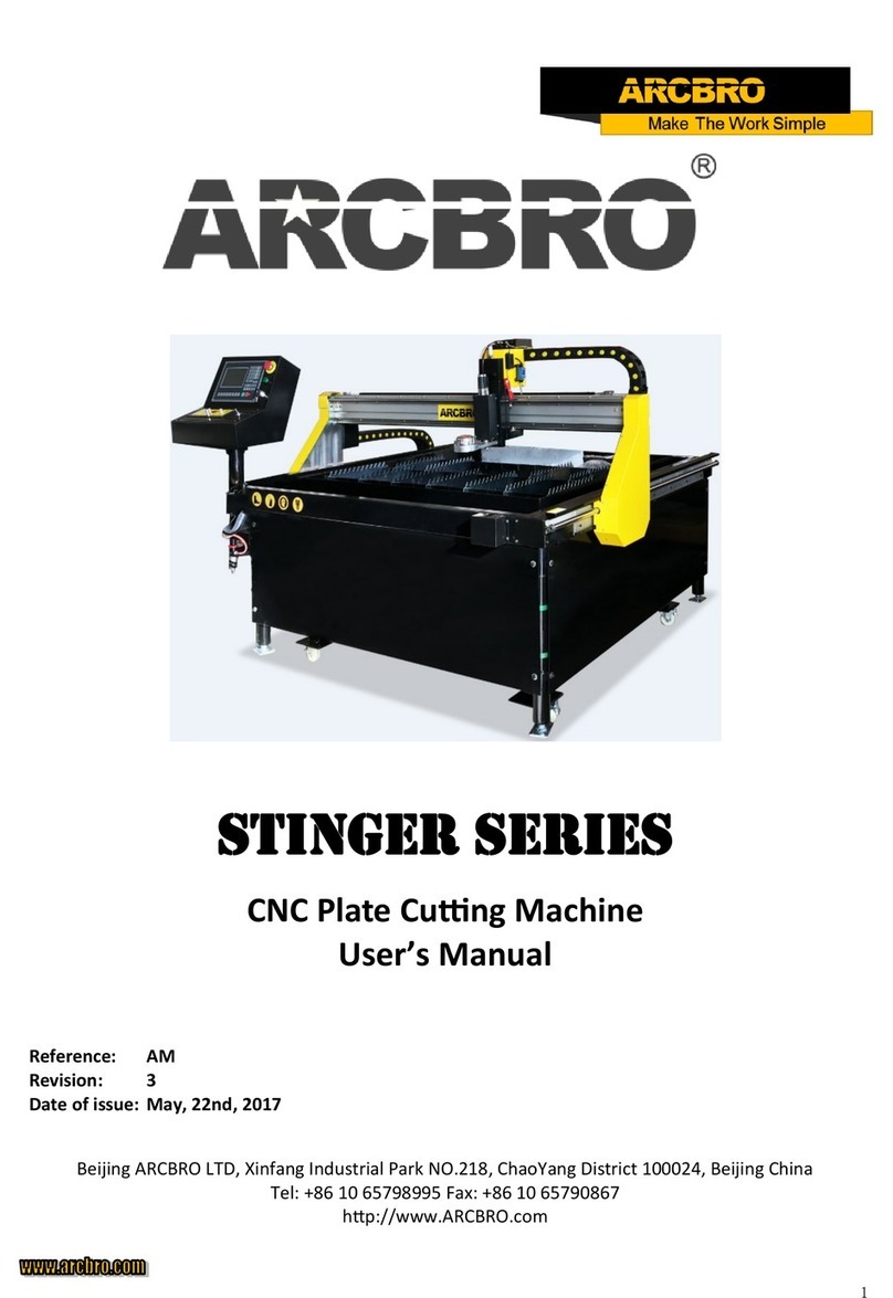
ARCBRO Stinger Series User manual

Service Support Spirit
Unique Solution WWW.ARCBRO.COM
1
Stinger SERIES
CNC Plate Cutting Machine User’s Manual
Operator Manual
ARCBRO| Revision 2 | English
Date of issue: August, 2019

Service Support Spirit
Unique Solution WWW.ARCBRO.COM
2
Contents
Technical Support.............................................................................................................................7
1. System Functions.........................................................................................................................8
1.1. Technical specifications .........................................................................................................9
2. Main Menu.................................................................................................................................10
2.1. Menu Features.....................................................................................................................10
2.2. Description of Main Menu ...................................................................................................10
3. Automatic Function(AUTO).........................................................................................................12
3.1. Description of Automatic Mode Interface.............................................................................13
3.1.1 SPEED ...........................................................................................................................13
3.1.2 Program, Pierce and KERF ............................................................................................13
3.1.3 Work Mode--OPERATE..................................................................................................14
3.1.4 Input and output ............................................................................................................14
3.1.5 Machining Parameters ...................................................................................................14
3.1.6 Coordinate unit ..............................................................................................................14
3.1.7 The six control keys on the Keyboard............................................................................14
3.1.8【1】→ZOOMIN ..........................................................................................................15
3.1.9【2】→ZOOMOUT.......................................................................................................15
3.1.10【X】→TEST..............................................................................................................15
3.1.11【Y】→AU-SPD.........................................................................................................15
3.2. Function selection in AUTO mode .......................................................................................15
3.2. 1【F1】→SECTION .......................................................................................................15

Service Support Spirit
Unique Solution WWW.ARCBRO.COM
3
3.2.2【F2】→MAN ..............................................................................................................16
3.2.3【F3】→RE-BREAK .....................................................................................................16
3.2.4【F4】→VIEW..............................................................................................................16
3.2.5【F5】KERF ..................................................................................................................17
3.2.7【F8】RETURN.............................................................................................................17
3.2.6【F6】OTHERS.............................................................................................................18
3.3. Automatic startup.................................................................................................................22
3.3.1 Cutting speed ................................................................................................................22
3.3.2 Automatic machining start..............................................................................................22
3.4. Adjustment of cutting position of automatic control.............................................................22
3.4.1 In the process of automatic processing, only the keystrokes effective:..........................22
3.4.2 Pause after the adjustment of position of the cutting.....................................................24
3.5. Original Path Return ............................................................................................................25
3.5.1 Return along original path..............................................................................................25
3.5.2 Return at G00(when reach a piercing point) ..................................................................26
3.5.3 Operation after returned.................................................................................................26
3.5.4 Repeat the above operation procedure until the desired effect is achieved....................26
3.5.5 To exit machining mode ................................................................................................26
3.5.6 Total row number and beginning row in return process................................................26
3.6. Breakpoint Restoration Process ...........................................................................................27
3.6.1 Breakpoint restoration....................................................................................................27
3.6.2 Attention: .......................................................................................................................28

Service Support Spirit
Unique Solution WWW.ARCBRO.COM
4
3.7. SECTION(section selection).................................................................................................28
3.7.1 Start SECTION function..................................................................................................28
3.7.2 Two cases for SECTION machining option: ...................................................................29
3.8. MOVE HOLE for Thick Plate.................................................................................................30
3.8.1 HOLE .............................................................................................................................30
3.8.2 MOVE HOLE ..................................................................................................................30
3.8.3 NO HOLE .......................................................................................................................30
4. MAN(Manual Mode)...................................................................................................................31
4.1. Description of Manual Mode Window..................................................................................32
4.1.1 [↑], [↓], [←], [→] directional control keys and [G] Continue Key ............................32
4.1.2【F1】AUTO .................................................................................................................32
4.1.3【F2】STEP ..................................................................................................................32
4.1.4【F4】CORR.................................................................................................................32
4.1.5【F5】H-SPED..............................................................................................................33
4.1.6【F6】CLS-CO ...........................................................................................................33
4.1.7【F8】RETURN.............................................................................................................33
4.1.8【F3】OTHERS.............................................................................................................35
5. EDIT Mode .................................................................................................................................39
5.1. Description of EDIT Menu ...................................................................................................39
5.1.1【F1】NEW...................................................................................................................39
5.1.2【F2】LOAD .................................................................................................................39
5.1.3【F3】SAVE..................................................................................................................40

Service Support Spirit
Unique Solution WWW.ARCBRO.COM
5
5.1.4【F4】DELE ..................................................................................................................40
5.1.5【F5】DELL ..................................................................................................................40
5.1.6【F6】USB- ..................................................................................................................41
5.1.7【F7】VIEW...................................................................................................................41
6. Command System ......................................................................................................................42
6.1. Description of Programing Symbols....................................................................................42
6.2. Coordinate System ..............................................................................................................42
6.3. G: Basic Preparatory Commands.........................................................................................43
6.4. M Auxiliary Commands .......................................................................................................48
7. SETUP (Parameter Setting) ........................................................................................................51
7.1. Parameter Description .........................................................................................................51
7.2. SETUP(parameter setting) ...................................................................................................52
7.2.1 Speed parameters..........................................................................................................52
7.2.2 System parameters ........................................................................................................54
7.2.3 Flame Cutting Parameters..............................................................................................56
7.2.4 Plasma Parameters Setting ............................................................................................58
7.2.5 Control Parameters Setting............................................................................................59
8. LIBMINIT (Library of Patterns)....................................................................................................63
8.1. LIBMINIT Setting .................................................................................................................63
8.2. Selection of Pattern Elements..............................................................................................64
8.3. Arrangement and Layout of Pattern Element........................................................................64
9. Diagnose ....................................................................................................................................66

Service Support Spirit
Unique Solution WWW.ARCBRO.COM
6
9.1. Check Input/output Ports.....................................................................................................67
9.2. Output Check.......................................................................................................................67
9.3. Input Check .........................................................................................................................67
10. System input/output interface connected .................................................................................68
10.1. The system input principle.................................................................................................68
10.2. The principle of the system output: ...................................................................................69
10.3. Input/output connect definition..........................................................................................69
10.4. 15 core motor port definitions ...........................................................................................71
10.5. When using flame cutting typical wiring (DB15)................................................................72
Appendix I: Instructions for Software Upgrading Operation............................................................73
Appendix II: Troubleshooting .........................................................................................................74

Service Support Spirit
Unique Solution WWW.ARCBRO.COM
7
Technical Support
Thank you very much to choose ARCBRO product, our whole engineer department work for
you since the day you receive machine. When you have any questions during assembling or
operating, it is free to contact us by Call, Email, Online help 7x24 hours.
Wish you enjoy a wonderful CNC cutting travel.
ARCBRO CNC Technical Support & Solutions
7x24 Hours
+86-10-65798995
support@arcbro.com
www.arcbro.com/about-arcbro-cnc-cutting-solutions/

Service Support Spirit
Unique Solution WWW.ARCBRO.COM
8
1. System Functions
CNC System for Cutting is designed to work with torch/plasma, high-pressure water jet
and laser cutting machines and extensively used in metal working, advertisement
fabrication and stone machining businesses.
High reliability as well as good resistance to plasma disturbance lightning and surge.
Applied torch/plasma cutting technology, able to perform corner speed control and height
control automatically;
Kerf compensation, reasonability check and report for user's option;
Breakpoint restoration, automatic power-back recovery and automatic breakpoint memory,
Random section and piercing point selection,
Extended piercing for thick plate and bridging feature for thin plate,
Optional piercing position feature in mode of RETURN, SECTION(section selection) and
RESBREK(breakpoint restoration), very convenient for user control,
Ready for transitional cutting operation at any moment,

Service Support Spirit
Unique Solution WWW.ARCBRO.COM
9
Special short line machining feature based on smooth travel, extensively applicable to
metal blanking as well as advertisement and ironwork fabrication, etc.
Parts library of 24-type patterns, extensible and customizable, including the common
machining parts,
Operation menu both in Chinese and English, dynamic graphic display, 8-times zoom,
free point automatic tracking, USB disk program and timely software upgrade.
1.1. Technical specifications
Processor: Industrial ARM9 CPU
Display: 7" Color LCD
Input/output: 13 channels of optical isolation input and 8 channels of optical isolation
output
Interlocked axles: 2 axles, extensible to 4 interlocked axles
Maximum speed: <24m/min
Pulse equivalency: variable, electronic gear numerator and optional denominator in the
range from 1 to 65535
Memory space: 32M-64M oversized memory capacity for user program and no
restriction to machining program
Machine case size: 298×202×95.2(mm)
Operation temperature: 0 to +40℃; storage temperature: -40 to +60℃

Service Support Spirit
Unique Solution WWW.ARCBRO.COM
10
2. Main Menu
2.1. Menu Features
The design of hierarchy-based functional windows is adopted for system operating display.
If a function is invoked in the main menu window, the corresponding sub window menu will pop
up. Press [F1] to [ F7] to select the corresponding function according to window prompt. Press
ESC to abandon the selection and return to the upper level of menu.
Fig.1.1 Main menu display of system after booting
2.2. Description of Main Menu
VER : The version information of software and hardware is indicated at the bottom left corner for
your information.
【F1】AUTO : Programmed control of automatic machining.
【F2】MAN : To manually control the position of cutting nozzle.
【F3】EDIT:To edit/modify/input/output the machining program.
【F4】SETUP : To set system parameters.
Display space
of system
Software version

Service Support Spirit
Unique Solution WWW.ARCBRO.COM
11
【F5】DIAGNOSE: To check the input/output information of cutting machine.
【F6】LIBMINIT: To set normal pattern and plan material.
[G] [G] [3] Initial Setting : A dialog box as follows will appear:
Fig.1.2
Parameter: To restore the factory parameter setting;
FORMAT FILES: To format user's program space;
LANGUAGE: Choose language as show
Press PgUp/PgDN on the keyboard to select the language then press Enter;
Fig.1.3 select LAN

Service Support Spirit
Unique Solution WWW.ARCBRO.COM
12
3. Automatic Function(AUTO)
In the main menu, press [F1] to enter the automatic function window, as shown in the figure
below.
Fig. 3.1 Plasma Mode
Flame mode Fig. 3.2 Automatic Function (AUTO) Interface
Active speed
Program name
Function display area
Piercing Hole No. Kerf
Input/output
indication
Coordinates
Pattern Display
Space
Machining
parameter
Work mode

Service Support Spirit
Unique Solution WWW.ARCBRO.COM
13
3.1. Description of Automatic Mode Interface
In the system work under the main menu, press [F1] into the function of automatic main picture:
3.1 interface automatic way specification
3.1.1 SPEED
In automatic mode, at the top left corner of the screen, it shows F×(multiplying factor of automatic
machining speed)= Set machining speed.
In manual mode, at the top left corner of the screen, it shows F×(multiplying factor of manual
speed)=manual speed.
SPEED indicates the actual speed while the active speed multiplying factor is adjustable with [F↑] and
[F↓].
It is allowed to adjust the speed quickly by pressing [F] key in this Interface. And then, press ENTER key
to confirm the selection.
Note: The speed may be indicated in Metric or English system depending on the Metric/English Selection
in SETUP (Refer to Parameter Control).
3.1.2 Program, Pierce and KERF
They are used to indicate the name of machining program;

Service Support Spirit
Unique Solution WWW.ARCBRO.COM
14
Serial number of pierced hole(automatic clear in automatic machining mode)
The active compensating width of kerf respectively.
3.1.3 Work Mode--OPERATE
WORKMODE field indicates the active operating mode such as rotation selection, breakpoint
recovery, mirroring and section selection.
OPERATE field indicates such information as machining/pause, limit alarms and time delay.
3.1.4 Input and output
Below the heavy-current switches, there are 3 rows×8 indicators ○.
The top indicators show the status of 13 input ports, ○indicating no signal input and ●
indicating signal input.
The bottom indicators show the status of 8 output ports, ○indicating no signal output and ●
indicating signal output.
See the description of DIAGNOSE function for the definitions of input/output ports.
3.1.5 Machining Parameters
This zone indicates various parameter values in the current machining mode.
3.1.6 Coordinate unit
The coordinates may be indicated in Metric (mm) or English system(inch) depending on the
Metric/English Selection in SETUP(Refer to Parameter Control).
3.1.7 The six control keys on the Keyboard.
【IGNITION】: Refer to M20 for ignition feature.
【PREHEA】: To open the solenoid valve of preheating oxygen. Refer to M24for details.
【GAS】: To open the solenoid valve of acetylene(gas). Refer to M10 for details.
【CUT】: To open the solenoid valve of cutting oxygen; refer to M12 for details. To turn on the
arcing switch if it is plasma.
【PIERCE】heavy-current control key
A piercing process, the specific operation procedure is as follows:
Flame machining case: rise the cutting torch(M72), open the cutting oxygen(M12) and
lower the cutting torch(M73).
Plasma machining case: execute M07 command.

Service Support Spirit
Unique Solution WWW.ARCBRO.COM
15
Note: This is a very important feature. It will be used repeatedly in pause, return and extend
piercing operations. When preheat is done, pressing [PIERCE] key will start up piercing
operation directly.
【OFF】: To shut off all the heavy-current output.
【S↑】: Push it down to rise the cutting torch and release to stop the torch.
【S↓】: Push it down to lower the cutting torch and release to stop the torch.
3.1.8【1】→ZOOMIN
The pattern will be magnified one times by one keystroke
and it can be magnified to eight times maximum by three
keystrokes. As show pic.
3.1.9【2】→ZOOMOUT
To restore to normal pattern size. As show pic.
3.1.10【X】→TEST
If【X】key is pressed, the system will run the program
at top speed without executing M command. This feature is often used to position quickly or
check the working size of steel plate. This operation can be paused at any moment or cancelled
by pressing【X】key one more times.
3.1.11【Y】→AU-SPD
Since the manual speed and automatic speed is separate in the system, this key is used to
switched between automatic mode and manual mode to adjust the speed multiplying factor.
3.2. Function selection in AUTO mode
It is allowed to load a machining program by means of EDIT feature. If a program has been
loaded with same name, it can run directly. If the program is invoked from an USB disk,
especially a large program, it can be run directly with USB disk connected instead of saving it
into the system.
3.2. 1【F1】→SECTION
To assign system to start up machining operation from any section or piercing point.

Service Support Spirit
Unique Solution WWW.ARCBRO.COM
16
It is often used when machining needs to start from a certain section or only a part needs being
processed. Refer to SECTION feature for details.
3.2.2【F2】→MAN
To switch the system to manual mode.
3.2.3【F3】→RE-BREAK
After this function is selected, pressing【START】key to fulfil breakpoint restoration. Refer
to RE-BREAK feature for details.
3.2.4【F4】→VIEW
It is used to test the program for any error. When this feature is selected, the pattern of
machining program will be displayed with a cross cursor at the origin.
[S] key is used to magnify the pattern, one times by one keystroke and eight times maximum
by three keystrokes. [Q] key is used to return the pattern to original size. The display position of
pattern is moveable by pressing [↑], [↓], [←] and/or [→] key.
Fig. 3.3

Service Support Spirit
Unique Solution WWW.ARCBRO.COM
17
【F1】→N-PIERCE
Select the perforation position. This graphic has
6 perforation positions. You can select the
position according to the number.
【F2】→STARTP
Starting position; A graphic has four starting
positions, which are top left, bottom left, top right,
bottom right;
Every time you press the STARTP key it changes
a position
【F7】→INFORM:
Information: Displays details of the current
drawing
Fig. 3.5
3.2.5【F5】KERF
This key is used to reminder input of kerf compensating width; if no necessary to
compensate (usually in blanking), simply enter 0.
3.2.7【F8】RETURN
Two choices appear after pressing F8:
Choose the first one: RETURN TO REFERENCE;
【RETURN TO REFERENCE】: This position is the coordinate reset position;
【RETURN TO MACHINE ZERO】: It’s a constant position, usually in the lower left corner of
the machine

Service Support Spirit
Unique Solution WWW.ARCBRO.COM
18
3.2.6【F6】OTHERS
This key is used to enter the next interface as shown in Fig. 3.6below.
Fig. 3.6 OTHERS interface

Service Support Spirit
Unique Solution WWW.ARCBRO.COM
19
3.2.6.1.【F1】CONTOUR
Fig. 3.6.1 CONTOUR interface
The user before processing, can be determined by taking the contour line, the machining path
is beyond the scope of the steel sheet.
Press [F1] key to start walking contours, if not on the current torch reference point (coordinates
not zero), the system will prompt:
The current point positioning --- will torch the current position as a reference point.
Reference point location --- torch to return to the reference point, and then began
to walk contour.
When walking contours, if the torch over the range of steel, according to the [Pause] key to
move the position of the torch to the plate edge, then press [Start] button,
Then the system prompt: Modify the reference point "EN / ESC?" Press Enter to confirm the
reference point if changed, the current location will continue to operate as a contour line. Press
[ESC] to abandon changes. This operation can be repeated
many times do run until the position you prefer.

Service Support Spirit
Unique Solution WWW.ARCBRO.COM
20
3.2.6.2.【F2】WENTAI
The system will prompt to run WENTAI-based machining program if this key is pressed.
WENTAI is a word machining software for CAD/CAM, widely used in cutting graphic characters
in advertisement business. This feature is required to run a WENTAI-based program.
3.2.6.3.【F3】ROTAE {steel plate correcting feature}
3.2.6.3-1Machining at rotation angle
This feature is used when the steel plate is not positioned perfectly or the steel plate needs to
rotate an angle before machining. It is allowed to use Rotate function along with B E G . P T. and
E N D P T. in Manual mode or input the expected angle directly. After acknowledged, the system
will start the machining program at the appointed rotation angle.
Note: Counter clockwise direction is taken as positive angle.
3.2.6.3-2Example
The system is able to identify and calculate the rotation angle by measuring the origin point and
the end point of an edge of steel plate(a straight line). The procedure is as follows:
Determine the datum line. Take one borderline of steel plate as baseline and move the cutting
torch to the origin point of this baseline. Press [F2] to set the beginning point of measurement.
Control the cutting torch and let it move along the baseline to the end point. The larger distance
between the beginning point and the end point, the more accurate of the measurement. Aim
the cutting torch at the baseline and press [F3] to set the end point of measurement.
At this moment, the rotation angle of the datum line is calculated. After the rotate function is
fulfilled, the rotation angle will appear in the OPERATE field, as shown in Fig. 3.2 below.
3.2.6.3-4 [F4] MIRR
It is possible to select X Mirror, Y Mirror and No Mirror if press [F5] key continually. When X Mirror
is selected, the machining program will run along the symmetry direction of X-axis, as appears
inverted horizontally.
When Y Mirror is selected, the machining program will run along the symmetry direction of Y-
axis, as appears inverted vertically. When default No Mirror is selected, the machining program
will run normally.
Other manuals for Stinger Series
2
Table of contents
Other ARCBRO Cutter manuals