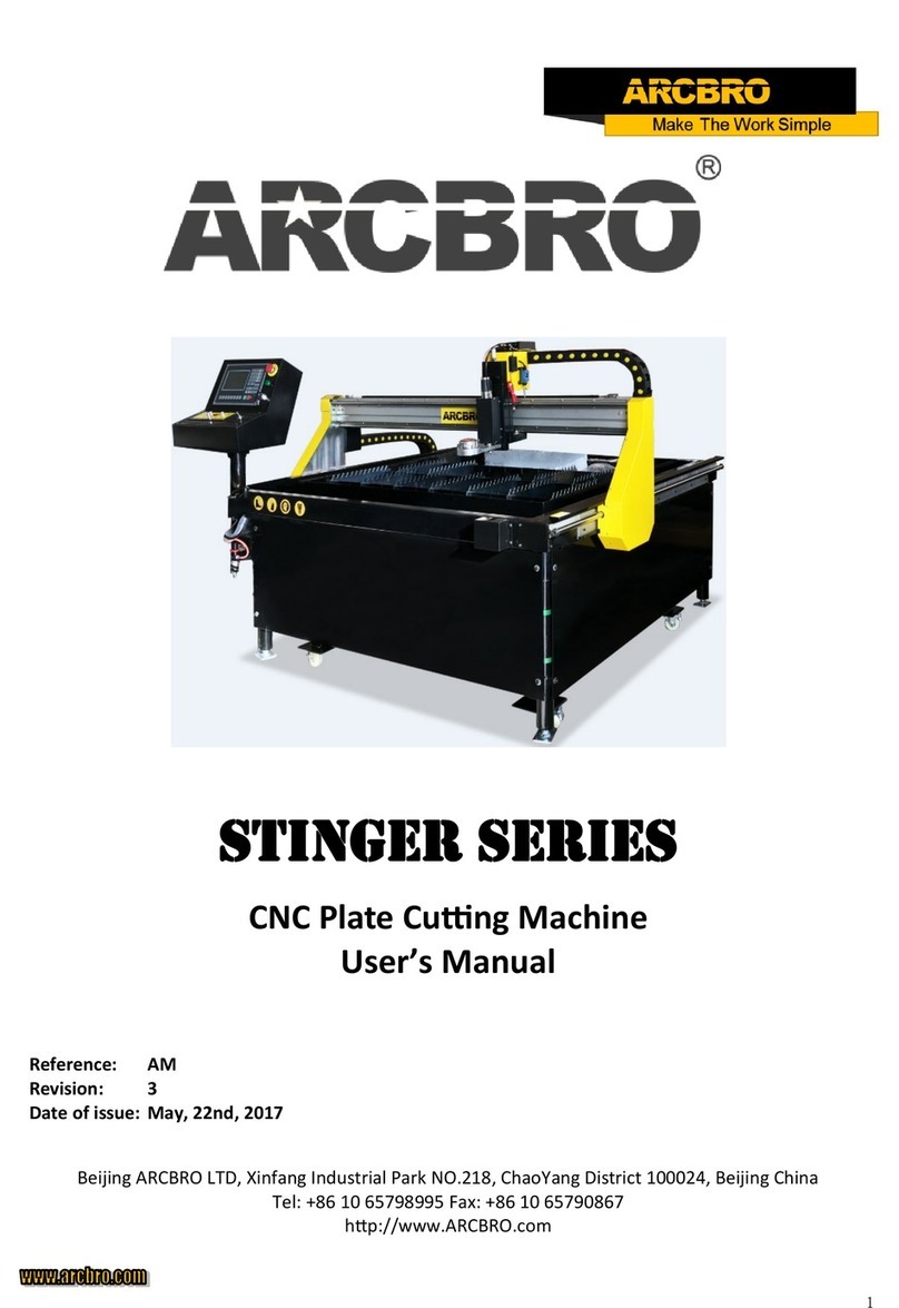
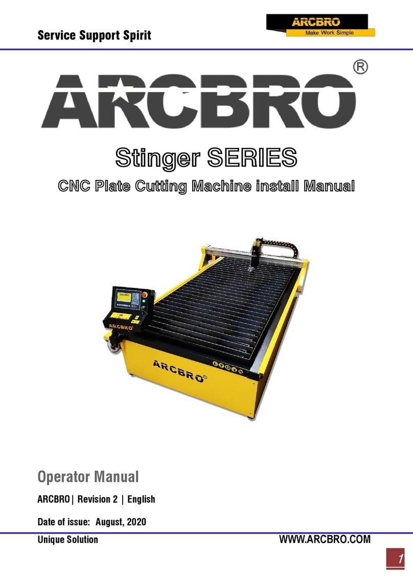
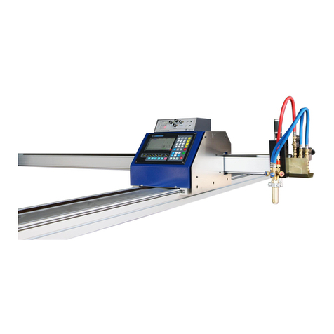
ARCBRO Voyager Series User manual

「Voyager Series」
CNC Portable Cutting Machine
User’s Manual
Reference: P 218-3
Issue: 1
Revision: 1
Date of issue: January, 2017
ARCBRO
Xinfang Industrial Park NO.218, ChaoYang District, 100024 Beijing, China
Tel: +86 10 65798995; Fax: +86 10 65790867
http://www.ARCBRO.com

Service Support Spirit
II
Unique Solution WWW.ARCBRO.COM
Changes may be made periodically to the information in this manual without
obligation to notify any person of such revisions or changes. Such changes
will be incorporated in new editions of this manual or supplementary
documents and publications. This company makes no representations or
warranties, either expressed or implied, with respect to the contents hereof
and specifically disclaims the implied warranties of merchantability or fitness
for a particular purpose.
No parts of this manual may be reproduced, stored in a retrieval system, or
transmitted, in any form or by any means, electronically, mechanically, by
photocopy, recording or otherwise, without the prior written permission of
ARCBRO Company.
This User’s Manual is only available for Voyager CNC Portable Cutting
Machine.
Ensure that the operator has read and understood this User’s Manual before
any operation on Voyager CNC Portable Cutting Machine.
There may be few differences between the pictures in this User’s Manual and
the machine you received.
Never hesitate to contact us for on-line technical service when you have any
questions or you need help, and it's our pleasure to serve for you. Our E-mail
is as follows:
SALES@ARCBRO.com

Service Support Spirit
III
Unique Solution
WWW.ARCBRO.COM
Contents
Technical Parameters.....................................................................................................6
Notes..............................................................................................................................7
1. Voyager Description...................................................................................................8
1.1. What is Cruiser mini? ..........................................................................................8
1.2. Application ..........................................................................................................8
1.3. Starting, Programming and Nesting....................................................................8
1.4. Composition........................................................................................................8
2. Safety .........................................................................................................................9
2.1. Information for your safety ................................................................................9
2.2 Caution sign........................................................................................................10
3. Packing List...............................................................................................................11
3.1. Introduction ......................................................................................................11
3.2. Packing List........................................................................................................11
4. Installation ...............................................................................................................12
4.1 Introduction .......................................................................................................12
4.2 Longitudinal rails assembly (Y- axis) ..................................................................12
4.3 Installation of the CNC controller ......................................................................16
4.4 Ground wire connection: .............................................................................17
4.5 Cable Connection instruction for Auto Plasma cut......................................17
4.6 Connection instruction for Auto Flame cut .................................................19
5. Installation of Nesting Software ..............................................................................21
6. Functional Overview ................................................................................................22
6.1. System Functions ..............................................................................................22
6.2Technical specifications ......................................................................................23
7. Main Menu...............................................................................................................24
7.1. Menu Features..................................................................................................24
7.2. Description of Main Menu................................................................................24
8. Automatic Function(AUTO)......................................................................................26
8.1. Description of Automatic Mode Window.........................................................27
8.1.1 SPEED ..........................................................................................................27
8.1.2 PROG, PIERCE and KERF ..............................................................................27
8.1.3 WORKMODE, OPERATE...............................................................................27
8.1.4 Input and output.........................................................................................27
8.1.5 Machining Parameters Indication............................................................27
8.1.6 Selection of coordinate unit ....................................................................28
8.1.7 The six heavy-current control keys on the front panel are designed to
exert heavy-current control of external source. .................................................28
8.1.8[1] BLOWUP .................................................................................................28
8.1.9 [2] RESTIT ....................................................................................................28
8.1.10 [X] TEST .....................................................................................................28
8.1.11 [Y] AU-SPD.................................................................................................29
8.2. Function selection in AUTO mode ....................................................................29
8.2. 1[F1] SECTION ................................................................................................29
8.2.2[F2] MAN......................................................................................................29
8.2.3[F3] RESBREK................................................................................................29

Service Support Spirit
IV
Unique Solution
WWW.ARCBRO.COM
8.2.4[F4] VIEW .....................................................................................................29
8.2.5[F5] KERF ......................................................................................................29
8.2.6[F6] ASSI .......................................................................................................30
8.2.7. [F3] ROTATE(steel plate correcting feature)..............................................30
8.2.8[F4] MIRR .....................................................................................................31
8.2.9 [F5] SCALE ...................................................................................................31
8.2.10 [F2] WENTAI..............................................................................................31
8.3. Start-up of speed mode (multiplying factor) and automatic mode .................31
8.3.1Manual speed and return speed..................................................................31
8.3.2Machining Speed .........................................................................................31
8.3.3Start of automatic mode..............................................................................32
8.4. Control and adjustment of cutting position in automatic mode......................32
8.4.1 Only the following keys are enabled when the system starts automatic
mode: ...................................................................................................................32
8.4.2. Adjustment of cutting position..................................................................33
8.5. Original Path Return..........................................................................................34
8.5.1Return along original path ...........................................................................34
8.5.2 Return at G00(when reach a piercing point) ..............................................34
8.5.4 Repeat the above operation procedure until the desired effect is achieved.
..............................................................................................................................35
8.5.5 To exit machining mode..............................................................................35
8.5.6 Total row number and beginning row in return process............................35
8.6. Breakpoint Restoration Process........................................................................36
8.6.1. Breakpoint restoration...............................................................................36
8.6.2Attention:.....................................................................................................37
8.7. SECTION(section selection)...............................................................................37
8.7.1. Start SECTION function ..............................................................................37
8.7.2. Two cases for SECTION machining option:................................................37
8.8. MOVE HOLE for Thick Plate ..............................................................................38
8.8.1HOLE.............................................................................................................38
8.8.2 MOVE HOLE.................................................................................................39
8.8.3 NO HOLE......................................................................................................39
9. MAN(Manual Mode)................................................................................................40
9.1. Description of Manual Mode Window .............................................................41
9.1.1 [↑], [↓], [←], [→] directional control keys and [G] Continue Key ............41
9.1.2 【F1】AUTO ..............................................................................................41
9.1.3 【F2】MOVE .............................................................................................41
9.1.4 [F2]P-START, [F3]P-END and Calibration function...................................41
9.1.5 【F6】CLS-CO..........................................................................................42
9.1.6 【F5】MDI..........................................................................................42
9.1.7 Speed .......................................................................................................42
10. EDIT Mode..............................................................................................................43
..................................................................................................................................43
10.1. Description of EDIT Menu...............................................................................43
10.1.1. 【F1】NEW ............................................................................................43
10.1.2. 【F2】LOAD ...........................................................................................43

Service Support Spirit
V
Unique Solution
WWW.ARCBRO.COM
10.1.3. 【F3】SAVE ............................................................................................43
10.1.4. 【F4】DELE.............................................................................................44
10.1.5. 【F5】DELL.............................................................................................44
10.1.6. 【F6】TRAN............................................................................................44
10.1.7. 【F7】SEARCH STRING ............................................................................44
11. Command System ..................................................................................................45
11.1. Description of Programing Symbols................................................................45
11.2. Coordinate System..........................................................................................45
11.3. G: Basic Preparatory Commands ....................................................................46
11.4. M Auxiliary Commands...................................................................................51
12. SETUP (Parameter Setting) ....................................................................................54
12.1. Parameter Description....................................................................................54
12.2. SETUP(parameter setting) ..............................................................................55
12.2.1. Speed parameters....................................................................................55
12.2.2. System parameters ..................................................................................56
12.3. Flame Cutting Parameters ..............................................................................58
12.4. Plasma Parameters Setting .............................................................................59
12.5. Control Parameters Setting ............................................................................60
13. LIBMINIT (Library of Patterns) ...............................................................................62
13.1. LIBMINIT Setting .............................................................................................62
13.2. Selection of Pattern Elements ........................................................................63
13.3. Arrangement and Layout of Pattern Element ................................................63
13.4. User Defined Module......................................................................................64
14. Diagnose.................................................................................................................65
14.1 Check Input/output Ports ................................................................................65
14.2 Output Check ...................................................................................................66
14.3 Input Check ...................................................................................................66
Appendix I: Instructions for Software Upgrading Operation of SH-2012AH...............67
Appendix II: Troubleshooting.......................................................................................68

Service Support Spirit
6
Unique Solution WWW.ARCBRO.COM
Technical Parameters
Type
Voyager 1220
Voyager 1530
Voyager 1860
Effective cutting range 1200x2000mm 1500x3000mm 1800x6000mm
Actual machine size 2000x2500mm 2300x3500mm 2600x6500mm
Input power supply 1 phase, 110V, 220V, 50Hz/60Hz
Input capacity 350W
Cutting model Both plasma and flame cutting
Max travel speed 8000mm/min
Drive motor Step motor
CNC SYSTEM
Display 7’’ color LCD screen
CPU Industrial ARM9 chip
Internal library 24 kinds of shapes
External format TXT or NC format
Language English, Chinese, Spanish, Russian, French, Japanese, Czech and Slovenia
PLASMA CUTTING MODE
Max cutting speed 6000mm/min
Max cutting thickness Depends on plasma power source
Plasma power source Support up to 125A ( not include in standard package )
THC Arc voltage Auto Torch Height Controller
Accuracy ±0.3mm
FLAME CUTTING MODE
Max cutting speed 1000mm/min
Max cutting thickness 150mm
Oxyfuel cutting torch 80mm neck ( can update to 180mm neck if necessary )
THC Manual/ Capacitance auto height controller (optional)
Optional cutting nozzle 4 nozzles ( #1, #2, #3, #4 ) for Acetylene or Propane ( standard package only include propane nozzle)

Service Support Spirit
7
Unique Solution WWW.ARCBRO.COM
Accuracy ±0.5mm
Notes
Note 1: Propane cutting nozzles are included in standard package. Acetylene nuzzles can be ordered.
Note 2: Specific torch assembly must be ordered for Gasoline project.
Note 3: Nesting software standard Wizard is included in standard package.
Note 4: The machine must be grounded reliably when it is working. (Connect the plate and the earth)
Note 5: Clean dust regularly to keep the rail and rack clean for smooth movement.
Note 6: Avoid damage for the LED display screen of CNC system.
Note 7: Equipment use environment:
Ambient temperature: -10℃—+50℃
Environment humidity: 90﹪RH below
Storage temperature: -20℃—+65℃
Sea level elevation: An altitude of 1000 m below

Service Support Spirit
8
Unique Solution WWW.ARCBRO.COM
1. Voyager Description
1.1. What is Voyager?
Voyager is a CNC portable Cutting Machine. It can cut any complex plane figures such as the large-
sized gantry, and Voyager can match both flame torch and plasma cutter.
Its design is compact and its structure is rational, which makes it lightweight, small size and easy to
move. Voyager is applicable both indoors and outdoors.
It is simple and efficient in drawing, nesting and cutting because of the installation of Fast CAM
cutting software.
1.2. Application
Voyager is an ideal CNC Cutting Machine for small, medium scale enterprises.
Voyager is used in industry field widely. It can cut and blanking metal plates such as carbon steel
(flame cutting), stainless steel, copper and aluminum (plasma cutting).
1.3. Starting, Programming and Nesting
The Computer Aided Design or manual drawing of parts can be prepared, nested and directly
transformed into required G-code if you set proper programming parameters. The G-code can be
stored in a USB key if you plug a USB key in the USB port of Voyager CNC cutting Machine. The G-
code is automatically transmitted and the cutting operation may start. The G-code can be transmitted
easily to the memory space of Voyager as well.
1.4. Composition
Voyager consists of a support structure and a central control unit.
The support structure composed of two longitudinal rails (Y Axis). The stability and rigidity of the rails
are guaranteed by two transversal beams.

Service Support Spirit
9
Unique Solution WWW.ARCBRO.COM
The Central Control Unit, containing the electronics commands ,the control panel, the display and
keyboard, moves on these rails and hold the cross beam (X-Axis) supporting the cutting torch.
2. Safety
2.1. Information for your safety
The operator must read and understood the contents of this user’s manual before any operation on
Voyager.
Never hesitate to contact us for assistance when you have any questions or you need help, and you
can reduce the account of time your troubles takes and solve your problem efficiently.
Note: Each of the following description must be verified before any operation on Voyager.
1. The preparing operations have to be performed by technicians that have plentiful experience.
2. All safety precautions must be obeyed in both flame and plasma cutting mode.
3. Keep Voyager away any explosive and flammable material.
4. Never try to cool, ventilate, flush Voyager with oxygen.
5. Grease and oily materials, even clothes, must be kept away from the oxygen.
6. The connectors of gas pipes and torch must be sealed without any leaks in safety.
7. The torch’s nozzle has to be selected according to the cutting to be performed.
8. Only Oxygen gas is available as combustion-supporting gas.
9. The Acetylene or Propane or Methane or Gasoline can be used as fuel gas.
10. Adjust the gas pressure to the following values:
Pre-heating Oxygen: Max 1.5 Mpa
Cutting Oxygen: Max 1.5 Mpa
Fuel: Max 0.1 Mpa
11. Torch ignition and flame adjustment have to be performed according this user’s manual.
12. The gas supply has to be turn off in accordance with the following order in case of backfire or
blockage of the nozzle.
a) Turn off fuel valve
b) Turn off pre-heating oxygen valve
c) Turn off cutting oxygen valve
13. All valves must be turn off when Voyager is not in use.
14. Maintenance must be carried out according to this user's manual, and any maintenance or repair
operations must be performed in the situation that the power supply is cut off.
15. Replacement of any parts must be performed by technicians that have plentiful experience and
only original parts are available.
16. Before operation, the operators must wear protective gloves, glasses, clothes, cross shoes, etc.
17. Handling means: because of equipment base guide at both ends long enough, with a handheld
parts, meanwhile, weight at about 75kg equipment two young people can raise, note carefully
handled and must ensure that equipment in a horizontal position(show as next picture)

Service Support Spirit
10
Unique Solution WWW.ARCBRO.COM
Controller
Notice:⑴: handle with care;
⑵: Put down, prevent hands and feet were clipped by machine;
⑶: Be careful equipment dumping or tip over.
18. The machine should be each half a month for rack-and pinion with lubricating oil.
19: The machine put in place before the ground level, ensure
2.2 Caution sign

Service Support Spirit
11
Unique Solution WWW.ARCBRO.COM
3. Packing List
3.1. Introduction
Voyager is packed carefully in two wooden boxes. All equipment in the boxes are protected fully to
avoid any damages during transportation.
The boxes have to be carried with care always and with the top cover up during handling and
transportation.
3.2. Packing List
Open the top cover of the boxes, and remove all the screws fixing the cover to the box body. The
Voyager transportation boxes contain:
No.
Name
No.
Name

Service Support Spirit
12
Unique Solution WWW.ARCBRO.COM
4. Installation
4.1 Introduction
Remove all the screws which are fixed the box, check and confirm all the spare parts be inside and
well, and then move all the parts out safely.
Install the machine carefully step by step as the following instructions:
4.2 Longitudinal rails assembly (Y- axis)
Note: the totally 3 types of Voyager transversal width are: 1.3m, 1.5m and 1.8m. The basic length of
Y-axis Rail is 2.5M. And it can be extended to the longest 15m by every extension in 1M.
1. Take out two sections of the longitudinal rails structure.
2. Take 16 pieces M5 bolts and square pad out, put 8 pieces nuts into the channel on each inner side
of the aluminium frame, with 4 pieces in each end of the two sections. Show as picture1.
Picture1. On each side, put 8 pads
3. Align the two sections and make them connected well show as picture2
1
CNC control system
2
Cross beam
3
Frame rail
4
ARCBRO customized USB pen
5
ARCBRO Wizard auto nesting software
6
Voyager User Manual
7
Sliding blocks
8
Torch height controller (THC)
9 Ground wire 10
Torch holder: Mechanical control holder (Auto
control holder for plasma is optional)
11
Solenoid valves
12
Propane cutting nozzles
13
Seal capping
14
Stepping motors
15
Oxy fuel cutting torch (80mm neck) and hoses
16
Machine Power supply cable
17
Cushion blocks
18/19
Arc Start & Arc voltage wire

Service Support Spirit
13
Unique Solution WWW.ARCBRO.COM
Picture 2 make the section of the rack and rail tightly fitted
4. Take out the 16 bolts, plug in 8 pieces for each side, and tighten them with the corresponding nut
show as picture 3.
Picture3 tighten all the screws one by one
Picture 4 the connected rail
5. Overturn the rail (upside down) 180 degree to make the rail facing downward. show as picture 5

Service Support Spirit
14
Unique Solution WWW.ARCBRO.COM
Pictures 5 overturn the rail
6. Take two pieces of 650mm long Longitudinal Cushion Block (with 4 bolts on it) out, plug the 4
quadrate nuts of cushion block into the channel from the end of the rail. show as picture 6
Repeat the last step, assemble the other longitudinal cushion block, and have the centre of the
Transversal cushion block fixed to the joint of the frame.
Picture 6 the assembly for the Transversal cushion blocks on the joint of the rails

Service Support Spirit
15
Unique Solution WWW.ARCBRO.COM
7. Take two pieces of 650 mm long Transversal cushion block (with two bolts on it),
Plug the nuts of cushion block into the 2 channels from the end of the frame. Show as picture 7.
Repeat the last step, assemble another one Transversal cushion block, and have them fixed to the
point that 1000mm to each end of the frame.
Picture 7. Fix the 2 blocks 1000mm to the end of the frame
8. Take another two pieces of the 1000mm (with two bolts on it) Transversal cushion block, Plug
the nuts of cushion block into the 2 channels from the end of the frame. show as picture 8
Repeat the last step, assemble another Transversal cushion block, and have them fixed to the point
that 1000mm to each end of the frame.

Service Support Spirit
16
Unique Solution WWW.ARCBRO.COM
Picture 8 fix the 2 blocks 200mm to the end of the frame
9. Tighten all the screws, overturn the rail to make it up, then the assembly of the rail is finished.
4.3 Installation of the CNC controller
1. Turn around the rail to back side, install rail connect plate by 16 bolts, as Picture 2 shows
2. Align the wheels of the Controller unit and the guiding rail, Push the Controller unit to slide in
along the Guide Rail, Show as Picture 4 and Picture 5.
Push the Central Unit to the direction show as the picture
Central Unit installation- detail picture

Service Support Spirit
17
Unique Solution WWW.ARCBRO.COM
9.4 Ground wire connection:
Find the Ground wire point on the longitudinal rail frame (100mm from the
end); Plug the nut into the channel and screw it up; Clamp its other end to
the plate you want to cut.
9.5 Cable Connection instruction for Auto Plasma cut

Service Support Spirit
18
Unique Solution WWW.ARCBRO.COM
9.5.1 Specification of Wiring Panel. Show as picture.
9.5.2 Wring instruction to plasma source-Using PMX105 as an example:
Signal Type Cable Note
Hypertherm
PMX105
ARC START
Output CNC IN1 Normal open;dry contact closure; used
for torch ignition
3
ARC START 4
DIV ARC+
Input CNC IN2
Receive the signal of raw arc voltage
from plasma, normally, the value of the
voltage is between 50VDC to 300VDC
J27
DIV ARC- J28
9.5.3 Torch installation and height adjustment:
Adjust the screw of the torch holder to insert the Torch; Fix the torch vertically in right position;
Connect the THC cable and attach the red IHS wire onto torch Shield.
THC cable
ARC START
DIV ARC+/-
Power
Offline
Plasma
Flame

Service Support Spirit
19
Unique Solution WWW.ARCBRO.COM
Picture 9 Picture 10
9.5.4
Push up the knob on Wiring Panel of Controller for Plasma mode; Set the proper SET VOLTAGE
(default value is 120 for Carbon Steel thickness range 5-6mm), IHS value by the screw on the THC,
you can go to the Controller to start an Auto Plasma cut.
9.6 Connection instruction for Auto Flame cut
Assemble part
Presentation
Qty
Part No.
CHC holder device (for flame auto height control)
(Optional) 1 unit ARC153049
80mm neck flame torch and hose 1 unit ARC153063
Propane cutting nozzles 4 pcs ARC153065
9.6.1 Device Instruction
Function: Automatically adjust the torch Height according to level difference of the steel plate.
Work theory: To feel the distance between the capacity ring sensor and the steel plate, then
Torch
Holder
Screw
Ground
Wire
THC
Cable
Plug
Lifter
Up/Dn
Button

Service Support Spirit
20
Unique Solution WWW.ARCBRO.COM
feedback this signal to CHC, THC and PCB and get order to adjust the torch height accordingly even
if the steel plate surface is rough or not horizontal.
Advantage: Avoid collision between nozzle and steel plate, extend service life of the torch/nozzle.
9.6.2 Assemble steps:
1. Attach the flame torch onto the standard torch holder, fix its screw.
2. Clamp the CHC holder device onto the flame torch, above the standard torch holder.
3. Fix the screw of the CHC holder well.
4. Connect the two ends of white Solenoid Valve cable plug.
Note: If the CHC holder device is not in purchase list, overlook step 2/3/4.
example:
9.6.3
Push down the knob on Wiring Panel of Controller for Flame mode; Set the proper SET VOLTAGE
(default value is 220 for Carbon Steel thickness range 10-30mm), IHS value by the screw on the THC,
you can go to the Controller to start an Auto flame cut.
CHC holder
device
Capacity
Wire
Connecter
Solenoid Valve
cable plug
This manual suits for next models
3
Table of contents
Other ARCBRO Cutter manuals
Popular Cutter manuals by other brands

Celme
Celme CHEF PIZZA INOX RAVELLING MN Installation - use - maintenance

Inovent
Inovent Counter Roll Cutter user guide

Battipav
Battipav Super Pro 450 operating instructions

gweike cloud
gweike cloud Desktop 3D Laser Printer user manual

Lamello
Lamello Tanga Delta H operating instructions

KRUG+PRIESTER
KRUG+PRIESTER EBA Series operating instructions

Bosch
Bosch Professional GSC 18V-16 E Original instructions

Textron
Textron Klauke ESG 50CL manual

Habasit
Habasit AF-61/6 30 Series operating instructions

Brunner Anliker
Brunner Anliker ANLIKER L operating manual

Urrea
Urrea UP874 User's Manual and Warrantly

Husqvarna
Husqvarna K 3000 Cut-n-Break Operator's manual