ARCCAPTAIN CUT50 User manual

Dear Valued Customer,
Thank you very much for being our valued customer. ARCCAPTAIN welder was built by
high quality components, every single unit machine was passed multiple industry leading
laboratory tests to provide a great welding experience and performance.
For your safety, please read and understand this manual carefully before using this
product. Your satisfaction is our priority! For any question or concerns, please do not
hesitate to contact ARCCAPTAIN for SUPPORT :
service@arccaptain.com
www.arccaptain.com
Digital Welder Expert, Know You More
https://www.arccaptain.com

TABLE OF CONTENTS
1. SAFETY................................................................................................. 1
1.1 Precautions for installation........................................................................... 4
1.2 Precautions for operation............................................................................. 4
1.3 Precautions for discard................................................................................. 5
2. PRODUCT DESCRIPTION................................................................ 4
2.1 Technical parameters.................................................................................... 4
2.2 Size and weight..............................................................................................4
2.3 Composition and configuration.................................................................... 5
2.4 Functions and characteristics...................................................................... 6
2.5 System characteristics.................................................................................. 7
3. INSTALLATION AND CONNECTION..............................................8
3.1 Installation requirements.............................................................................. 8
3.2 Strap Installation.......................................................................................... 10
4. OPERATION....................................................................................... 11
4.1 Panel functions of CUT50...........................................................................11
4.2 Operation method........................................................................................12
4.3 Notes for cutting operation.........................................................................12
4.4 Cutting parameters table............................................................................ 13
4.5 Replacement of electrode and nozzle......................................................13
5. MAINTENANCE.................................................................................14
5.1 Daily maintenance....................................................................................... 14
5.2 Periodic check.............................................................................................14
6. TROUBLESHOOTING......................................................................16
Digital Welder Expert, Know You More
https://www.arccaptain.com

1
1. SAFETY
1.1 Precautions for installation
Beware of electric shock!
Install grounding device according to application
standard.
Do not touch live parts with naked skin, wet gloves or
wet clothes.
Be sure you are insulated from ground and workpiece.
Cover the cover plate of the machine before power on to
avoid an electric shock.
Confirm the safety of your working position.
Beware of fire hazard!
Please install the machine on non-combustible materials
to avoid a fire.
Make ensure there are no inflammables near the cutting
position to avoid a fire.
Beware of explosion!
Do not install the machine in an environment with
explosive gas to avoid an explosion.
.
1) Make sure the place to install the machine can bear the weight of the cutting machine.
2) Do not install the machine at places where water droplet splash may be produced,
such as near water pipes.
3) Cutting should be carried out in dry environment with humidity of 90% or less.
4) The temperature of the working environment should be between -10℃and 40℃.
5) Avoid cutting in the open air unless sheltered from sunlight and rain. Keep it dry at all
times and do not place it on wet ground or in puddles.
6) Avoid cutting in dusty area or environment with corrosive chemical gas.
7) Do not carry out cutting with the cutting machine placed on a platform with a pitch
greater than 10°.
Over current/over voltage/over heating protection circuit is installed in this machine. When
the mains voltage, output current or inner temperature exceeds the set standard, the
machine will stop automatically. However, excessive use (e.g. too high voltage) of
machine may also damage the machine, so please note:
Digital Welder Expert, Know You More
https://www.arccaptain.com

2
Good ventilation
This cutting machine can create powerful cutting current and has strict cooling
requirements that cannot be met with natural ventilation. Therefore the built-in fan is
very important in enabling the machine to work stable with effective cooling. The
operator should make sure that the louvers be uncovered and unblocked. The
minimum distance between the machine and nearby objects should be 30cm.
Overvoltage is forbidden.
This machine is of automatic mains voltage compensation, which ensures that the
cutting current varies within the given range. In case that the input mains voltage
exceeds the tolerance value, it would possibly damage the machine. The operator
should understand this circumstance fully and adopt relevant precautions.
Overload is forbidden.
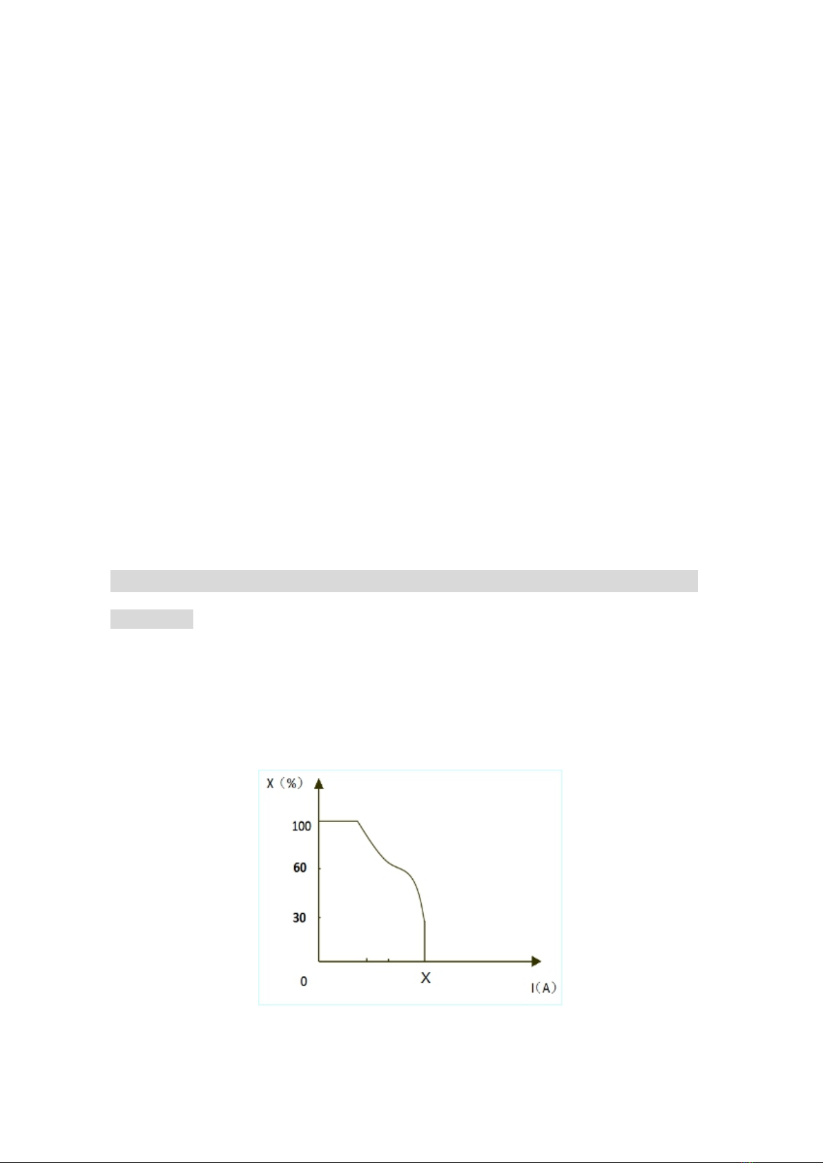
Remember to observe the max load current at any moment (refer to the
corresponding duty cycle). Make sure that the cutting current should not exceed the
maximum load current. Overload could obviously shorten the machine's lifespan, or
even damage the machine.
Suddenly the “E61” code may appear on the digital screen while the machine is of
over-load status. Under this circumstance, it is unnecessary to restart the machine.
Keep the built-in fan working to lower the temperature inside the machine. Cutting can
be continued after the inner temperature falls into the standard range and the yellow
LED is off.
Replacing the components can be dangerous.
Only professionals can replace the components of the machine.
Make sure there are no foreign bodies such as wire leads, screws, gaskets and metal
bars falling into the machine inside when replacing the components.
Make sure the connecting wires inside the machine are correctly connected after
replacing the PCBs, and then the machine can be run. Otherwise, there is a risk of
damage to property
1.2 Precautions for operation
Smoke-may be harmful to your health!
Keep your head away from the smoke to avoid inhalation of
waste gas in cutting.
Keep the working environment well ventilated with exhaust or
ventilation equipment when cutting.
Arc radiation-may hurt your eyes and burn your skin!
Use proper mask and wear protective clothing to protect your
eyes and body.
Use proper mask or curtain to protect onlooker from being
injured.
Digital Welder Expert, Know You More
https://www.arccaptain.com

3
Magnetic field can make cardiac pacemaker a bit wonky.
People with cardiac pacemaker should consult the doctor
before carrying out cutting.
Stay away from the power source to reduce the affect of
magnetic filed.
Improper use and operation may result in a fire or an
explosion.
Cutting spark may result in a fire, so please make ensure there
are no inflammables near the cutting position, and pay
attention to fire safety.
Ensure there is fire extinguisher nearby, and make sure
someone has been trained to operate the fire extinguisher.
Do not cut closed container.
Do not use this machine for pipe thawing.
Hot workpiece can cause severe scald.
Do not touch hot workpiece with bare hands.
Cool the cutting torch for a while after continuously working.
Excessive noise does great harm to people’s hearing.
Wear ear covers or other hearing protectors when cutting.
Give warning to onlooker that noise may be potentially
hazardous to hearing.
Moving parts may injure your body.
Please keep away from moving parts (like fan).
Each door, panel, cover, baffle plate, and protective device the
like should be closed and located correctly.
Seek professional support when trouble strikes.
When trouble strikes in installation and operation, please
inspect according to related contents in this manual.
If you still cannot understand fully, or you still cannot solve the
problem, please contact the dealer to obtain professional
support.
1.3 Precautions for discard
Pay attention to the following when discarding the cutting machine:
Burning the electrolytic capacitors in the main circuit or on the PCBs may cause an
explosion.
Burning the plastic parts such as the front panel may produce poisonous gas.
Dispose it as industrial waste.
Digital Welder Expert, Know You More
https://www.arccaptain.com

4
2. PRODUCT DESCRIPTION
2.1 Technical parameters
2.2 Size and weight
Model CUT50
Overall size (L*W*H) 474*150*244mm/18.7*5.9*9.6in
Weight (kg) 6kg/13lb
Items
Models
CUT50
Rated input power supply Single-phase AC110V 50Hz Single-phase AC220V 50Hz
Rated input capacity (kVA) 5.0 7.9
Power factor 0.63
Rated output (A/V) 35/94 50/100
Rated duty cycle (%) 60
No-load voltage (V) 280
Output current range (A) 20~35 20~50
Arc ignition mode HF contact
Post-flow time (s) 5~15
Gas pressure range (Mpa) 0.3~0.5
Insulation grade H
Cooling mode Air cooling
Enclosure ingress protection IP21S
Efficiency (%) 84
Digital Welder Expert, Know You More
https://www.arccaptain.com

5
Pic 1 Appearance and size of the machine (Unit: mm /inch)
2.3 Composition and configuration
1) Composition
Pic 2 Composition of the cutting machine system
Digital Welder Expert, Know You More
https://www.arccaptain.com

6
2) Configuration
Configuration of CUT50
Name Specification Quantity
(pcs)
Cutting machine CUT50 1
Cutting torch PT-31 16ft (5m) 1
Earth clamp 200A-16mm2(9ft/ 3m)DKJ 35-50 1
Operator’s manual Operator’s manual of CUT50 1
Gas hose 5*8mm Orange(9ft/ 3m)1
Conversion adapter American adapter plug 1
Shoulder Strap 0.1*4.3ft (30mm*1500mm), Black 1
2.4 Functions and characteristics
This is a digital plasma cutting machine with perfect function, high performance and
advanced technology. CUT50 is an ultra-portable plasma cutting system suitable for a
variety of application requirements. It can be used in handle cutting and robot cutting as
well. CUT50 can cut conductive metal, such as low carbon steel, stainless steel and
aluminum. The cutting thickness can reach up to 3/4'' (20 mm),quality cutting thickness
can reach up to 1/2'' (10mm), perforating thickness can reach up to 1/3'' (8 mm).
The forward-looking design concept of this machine and the application of a large number
of advanced and mature technologies can protect user’s investment to the greatest
extent.
Advanced digital control mode
Plasma cutting machine CUT50 adopts international leading MCU intelligent digital control
technology, and all its major parts are performed through software. It is a digital control
plasma cutting machine, improved a lot in its function and performance when compared
with the traditional plasma cutting machine.
Advanced inverter technology
With PWM technology and high power component IGBT, it inverts the DC voltage, which
is rectified from 50Hz/60Hz input AC voltage, to 30K~100KHz AC high voltage. Then the
voltage is dropped and rectified to output the high power DC power supply for cutting. The
machine adopts switching power supply inverter technology, greatly reducing the volume
and weight of the plasma cutter, and obviously enhancing the conversion efficiency.
Switching frequency is beyond audiorange, which almost eliminates the noise pollution.
Good consistency and stable performance
Digital Welder Expert, Know You More
https://www.arccaptain.com

7
Generally speaking, for a cutting machine with analogue circuit control or with analogue
circuit & digital circuit control, the performance characteristics are decided by the
parameters of various components. Cutting performance of the machines differ as a result
of the inconsistent parameters of the components, so even for the cutting machines of the
same brand, their parameters often differ from each other. In addition, cutting
performance of the machine may change on some extent, since parameters of the
components may vary according to the environment such as temperature and humidity,
etc.
One of the characteristics of digital control is that it is not sensitive to the change of
parameters; the performance of cutting machine will not be affected by the change of the
parameters of certain parts. Therefore, the consistency and stability of digital control
cutter is better than that of traditional cutter.
Powerful cutting performance
This machine is economic and practical since it can cut metals by adopting compressed
air as the plasma gas source. The cutting speed has increased by 1.8 times when
compared with oxyacetylene cutting. It can cut thick steel plates such as stainless steel,
copper, cast iron and aluminum conveniently and quickly. It is easy to ignite arc by
adopting HF arc ignition mode, and post-flow function is available. With simple operation
and high cutting speed, smooth cutting surface can be obtained, and polishing is
unnecessary.
2.5 System characteristics
Duty cycle
Rated duty cycle refers to the percentage of the normal work time of the machine under
rated maximum current holding in the period when taking 10 minutes as a period. The rated
duty cycle of this machine is 60%. Using the cutting machine continuously overrunning the
rated load may lead to overheating of the machine, and frequently using the machine
overrunning the rated load may accelerate the aging of the machine or even burn the
machine.
Pic 3 Duty cycle
Digital Welder Expert, Know You More
https://www.arccaptain.com

8
3. INSTALLATION AND CONNECTION
3.1 Installation requirements
1) Connection of input cable
In order to ensure personal safety and avoid electric shock, please send the product
power plug the grounding and wiring box grounding device,reliable grounding protection.
A primary power supply cable is available for this cutting machine. Connect the power
supply cable to the rated input power. The primary cable should be tightly connected to
the correct socket to avoid oxidization. Check whether the voltage value varies in
acceptable range with a multi-meter.
The cross section of the leads used in the switching box should meet the requirements of
the maximum input capacity of the machine.
2) Connection of output cable
Line disconnecting switch
Install a line disconnecting switch at each power
supply, so that the power supply can be cut off
immediately in case of an emergency. The
disconnecting value of the switch should be equal to or
greater than the continuous rating of the fuse. In
addition, the switch should have the following feature:
·The power is cut off when the switch is at “OFF”
position.
Pic 4
Connection of cutting torch
Connect the center plug on the cutting torch to the
center socket of the power supply, and tighten It
clockwise to avoid gas leakage.
Pic 5
Connection of earth cable
Insert the quick plug on the earth cable into the output
terminal “+” on the front panel of the machine, and
tighten it clockwise.
Pic 6
Digital Welder Expert, Know You More
https://www.arccaptain.com

9
3) Operation of the reducer valve
Steps for reducer setting are as follows:
start the gas flow; lift the pressure control
knob upward; adjust the gas pressure to
the desired value by rotating the knob
(rotate to “+” direction to increase gas
pressure; rotate to “-” direction to reduce
gas pressure); press down the pressure
control knob to get the knob locked. The
water can be drained automatically for
auto-drain function is available for the
embedded filter reducer.
Pic 7 Installation of the reducer valve
4) Installation of the cutting torch
- Insert one end of the electrode into the torch head.
- Insert the other end of the electrode into the
distributor.
- Connect the nozzle with the electrode and
distributor.
- Connect the protective sleeve with the nozzle, screw
it into the torch head, and tighten it.
Pic 8 Installation of cutting torch head
Digital Welder Expert, Know You More
https://www.arccaptain.com

10
3.2 Strap Installation
Step 1: Separate the velcro.(See Pic 9)
Pic 9
Step 2: Pull out one side through the
strap hole on the front panel with hook
side of the velcro up.(See Pic 10)
Pic 10
Step 3: Pull out it to well stick hook side
of the velcro to loop side and across
the nylon buckle.
Repeat it on the other side.(See Pic 11)
Pic 11
Step 4: Adjust the length by pulling the
nylon buckle (as shown in the
picture).(See Pic 12)
Pic 12
Step 5: Proper state after installation:
1. Strap does not twist;
2. Buckle side of shoulder pad is up,
while its flat side faces the machine (as
shown in the picture);
3. Straps are well locked.(See Pic 13)
Pic 13
Digital Welder Expert, Know You More
https://www.arccaptain.com

11
4. OPERATION
4.1 Panel Functions of CUT50
Part name Function Picture
1.Digital screen To display the cutting information
2. Operation mode button For 2T/4T cutting mode conversion
3. “+”Output terminal To connect the earth cable
4. Interface for torch
trigger
To connect the control signal of
cutting torch
5. “-”Output terminal To connect the cutting torch
6. Preferences button For Current/PostGas conversion
7.Current control knob To adjust the output current/post gas
value
1.Power switch To control the ON/OFF of th e input
power of the machine
2.Cable For power supply input
3.Cooling fan For heat dissipation through forced
air cooling
4.Air reducer valve To adjust the pressure of the input air
Digital Welder Expert, Know You More
https://www.arccaptain.com

12
4.2 Operation method
1) Turn on the power switch of the machine, and the power indicator illuminates.
2) Select proper working mode and proper function. There are two working modes
available on the machine panel: 2T and 4T.
3) Push the torch trigger on the cutting torch, the cutting machine works.
4) Set cutting current according to the thickness of workpiece.
5) Bring the copper nozzle of the cutting torch into contact with the workpiece (For
models with pilot arc function, keep a distance of about 2mm between the copper
nozzle of the torch and the workpiece.), and then push the torch trigger. After the arc
is ignited and started, raise the cutting torch to the position about 1mm above the
workpiece, and start cutting.
4.3 Notes for cutting operation
It is recommended not to ignite the arc in the air if not necessary, for it
will shorten the lifespan of the electrode and nozzle of the torch.
It is recommended to initiate the cutting from the edge of workpiece,
unless penetration is needed.
Ensure spatters fly from the bottom of workpiece while cutting. If
spatters fly from the top of workpiece, it indicates that the workpiece
can not be fully cut because the cutting torch is moved too fast or the
cutting current is too low.
Keep the nozzle slightly touching the workpiece or keep a short
distance between the nozzle and workpiece. If the torch is pressed
against the workpiece, the nozzle may stick to the workpiece, and
smooth cutting is unavailable.
For cutting round workpiece or to meet precise cutting requirement,
molding board or other assistant tools are needed.
It is recommended to pull the cutting torch while cutting.
Keep the nozzle of cutting torch upright over the workpiece, and check
if the arc is moving with the cutting line. If the space is not enough,
don’t bend the cable too much, step on or press upon the cable to
avoid suffocating of gas flow. The cutting torch may be burned
because the gas flow is too small. Keep the cutting cable away from
edge tools.
Clean up the spatters on the nozzle timely, for it will affect the cooling
effect of the nozzle. Clean up the dust and spatters on the torch head
after using everyday to ensure good cooling effect.
Digital Welder Expert, Know You More
https://www.arccaptain.com

13
The workpiece is not cut fully. This may be caused by:
1) The cutting current is too low.
2) The cutting speed is too high.
3) The electrode and nozzle of the torch are burned.
4) The workpiece is too thick.
Molten slag drops from the bottom of workpiece. This may be caused by:
1) The cutting speed is too low.
2) The electrode and nozzle of the torch are burned.
3) The cutting current is too high.
4.4 Cutting parameters table
Select proper current according to the cutting parameters table, workpiece material,
cutting thickness and cutting speed, etc. (The figure in the below table is an
approximation.)
Cutting speed (meter/min) when cutting current is 50A
4.5 Replacement of electrode and nozzle
When the phenomena below occur, the electrode and nozzle should be replaced.
Otherwise, there will be strong arc in the nozzle, which will break down the electrode and
the nozzle, or even burn the torch. Nozzles of different models are different, so ensure the
nozzle is of the same model when replacing it.
1) Electrode wear>1.5mm
2) Distortion of the nozzle
3) Cutting speed declining, arc with green flame
4) Difficult in arc ignition
5) Irregular cut
Digital Welder Expert, Know You More
https://www.arccaptain.com

14
5. MAINTENANCE
5.1 Daily maintenance
WARNING
The power of the switching box and the cutting machine should be shut down
before daily checking (except appearance checking without contacting the
conductive body) to avoid personal injury accidents such as electric shock and
burns.
Tips:
1) Daily checking is very important in keeping the high performance and safe operation
of this cutting machine.
2) Do daily checking according to the table below, and clean or replace components
when necessary.
3) In order to ensure the high performance of the machine, please choose components
provided or recommended by dealer when replacing components.
4)
Daily checking of the cutting machine
Items Checking requirements Remarks
Front panel
Whether any of the components are damaged or loosely
connected;
Whether the output quick sockets are tightened;
Whether the abnormity indicator illuminates.
If unqualified,
check the
interior of the
machine, and
tighten or
replace the
components.
Back panel
Whether the input power cable and buckle are in good
condition;
Whether the air intake is unobstructed.
Cover Whether the bolts are loosely connected. If unqualified,
tighten or
replace the
components.
Side plates Whether the side plate is loosely fixed.
Chassis Whether the screws are loosely connected.
Routine
Whether the machine enclosure has color fading or
overheating problems;
Whether the fan sounds normal when the machine is
running;
Whether there is abnormal smell, abnormal vibration or
noise when the machine is running.
If abnormal,
check the
interior of the
machine.
Digital Welder Expert, Know You More
https://www.arccaptain.com

15
Daily checking of the cables
Items Checking requirements Remarks
Earth cable Whether the grounding wires (including workpiece
GND wire and cutting machine GND wire) break off.
If unqualified,
tighten or replace
the components.
Cutting
cable
Whether the insulating layer of the cable is worn, or the
conductive part of the cable is exposed;
Whether the cable is drawn by an external force;
Whether the cable connected to the workpiece is well
connected.
Use appropriate
methods
according to the
work site
situation to
ensure safety
and normal
cutting.
5.2 Periodic check
WARNING
Periodic check should be carried out by qualified professionals to ensure safety.
The power of the switching box and the cutting machine should be shut down
before periodic check to avoid personal injury accidents such as electric shock and
burns. Due to the discharge of capacitors, checking should be carried out 5
minutes after the machine is powered off.
Tips:
Safety
All maintenance and checking should be carry out after the power is
completely cut off. Make sure the power plug of the machine is pulled
out before uncovering the cutting machine.
When the machine is powered on, keep hands, hair and tools away
from the moving parts such as the fan to avoid personal injury or
machine damage.
Periodic check
Check periodically whether inner circuit connection is in good
condition (esp. plugs). Tighten the loose connection. If there is
oxidization, remove it with sandpaper and then reconnect.
Check periodically whether the insulating layer of all cables is in good
condition. If there is any dilapidation, rewrap it or replace it.
Beware of static
In order to protect the semiconductor components and PCBs from the
static damage, please wear antistatic device or touch the metal part of
the enclosure to remove static in advance before contacting the
conductors and PCBs of the machine internal wiring.
Digital Welder Expert, Know You More
https://www.arccaptain.com

16
Keep it dry
Avoid rain, water and vapor infiltrating the machine. If there is, dry it
and check the insulation of the cutting machine (including that
between the connections and that between the connection and the
enclosure) with an ohmmeter. Only when there are no abnormal
phenomena anymore, can the machine be used.
Put the machine into the original packing in dry location if it is not to be
used for a long time.
Pay attention to maintenance
Periodic check should be carried out to ensure the long-term normal
use of the machine. Be careful when doing the periodic check,
including the inspection and cleaning of the machine interior.
Generally, periodic check should be carried out every 6 months, and it
should be carried out every 3 months if the cutting environment is
dusty or with heavy oily smoke.
Beware of corrosion
Please clean the plastic parts with neutral detergent.
6. TROUBLESHOOTING
Troubleshooting
The abnormity indicator on the front panel would illuminate in case of any failures inside
the cutting machine.
Malfunction phenomena Cause and solution
Turn on the machine, the LED screen
illuminates, the control PCB keys do
not function, and there is no response
when pushing the torch trigger.
The cutting machine crashes: Shut down the
machine, and restart it.
Turn on the machine, the LED screen
illuminates, the control PCB keys work
normally, but there is no response
when pushing the torch trigger.
1) The LED4 on the main board is on: The
control PCB is damaged.
2) The LED4 on the main board is off: Check
the torch trigger and torch trigger wire.
Turn on the machine, the LED screen
illuminates, and the fan works. When
pushing the torch trigger, the solenoid
valve functions, but there is no HF
discharge rustling.
The arc ignition part fails:
1) The interelectrode distance of the discharge
nozzle is too long.
2) There is leakage of the HF capacitor
222/15KV.
3) The mosfet or the optocoupler on the HF
board is damaged.
4) The input voltage is too low.
Arc can not be ignited. The air pressure is overly high or overly low.
Digital Welder Expert, Know You More
https://www.arccaptain.com

Digital Welder Expert, Know You More
https://www.arccaptain.com
Table of contents
Other ARCCAPTAIN Welding System manuals
Popular Welding System manuals by other brands

CIGWELD
CIGWELD 170Oi Service manual

Lincoln Electric
Lincoln Electric IDEALARC DC 1000 SVM123-A Service manual

Miller
Miller Millermatic 212 Auto-Set owner's manual

Sweiss
Sweiss SKY ARC Series user manual

Total
Total UTMGT1601 instruction manual

Abicor Binzel
Abicor Binzel ABITIG Little 9 Operating instruction