6
9) Radiated interference can develop in the following ways
• Direct interference from welder power source
• Direct interference from the welding leads
• Direct interference radiated from feedback into power lines
• Interference from re-radiation by ungrounded metallic objects
10) Keeping these contributing factors in mind, installing equipment as per following
instructions should minimize problems
• Keep the welder input power lines as short as possible and enclose as much of them as possible
in metal conduit or equivalent shielding.There should be a good electrical contact between this
conduit and ground(Earth).
• Keep the work and electrode leads as short as possible. Tape the leads together where practical .
• Be sure the torch and earth leads rubber coverings are free from cuts and cracks that allow
welding power leakage.
• Keep earth lead connection to work in good condition clean area on workbench where earth clamp
is situated on a regular basis.
11) Ventilation
This machine can create powerful welding current and has strict cooling requirements that cannot
be met with natural ventilation. Therefore machine to work stable with effective cooling.The
minimum distance between the machine and nearby objects should be 20mm.
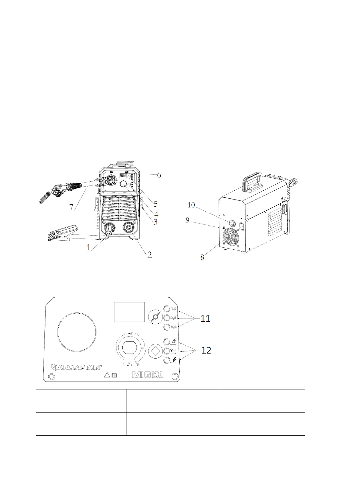
3.2 Input Power Connection
• The machine has one input connection,the power input cable. The power input cable is located on
the rear.
• The MIG130(N2HAB)is provided with a 110V cables,2.0M in length, with a 16Amp 5-15P plug
molded onto the cord;
• The MIG130(N2A9) is provided with a 230V cables, 2.0M in length, with a 16Amp 5-15P plug
molded onto the cord.
• The MIG130(N2A8) is provided with a 110V/220V cables,2.0M in length, with a 16Amp 5-15P plug
molded onto the cord;
• The rated output of the MIG130 is available when connected to a 40A branch circuit .when
connected to a branch circuit with lower capacity, lower welding current and duty cycle must be
used.
• The primary cable should be tightly connected to the correct socket to avoid oxidization.
• Check whether the voltage value varies in acceptable range with a multi-meter.
• The mains supply voltage should be within within ±15% of the rated mains supply voltage.Too low
a voltage may cause poor welding performance.Too high a supply voltage will cause components
to overheat and possibly fail.
Digital Welder Expert, Know You More
https://www.arccaptain.com