2” Round In-Ground Mailbox Post with Side Braces (Model 7511)
Assembly Instructions
Assembly Instructions
Thank you for purchasing this premium mailbox post. We know you'll be satisfied with the years of service it will provide. If you have any questions about how to
assemble
or
install
this
product,
or
if
you
need
any
replacement
parts,
please
call
us
directly
at
(800)
464-7491
or
contact
us
at
[email protected].
Phillips head screwdriver
Tools (not included)
Two open end wrenches
- or -
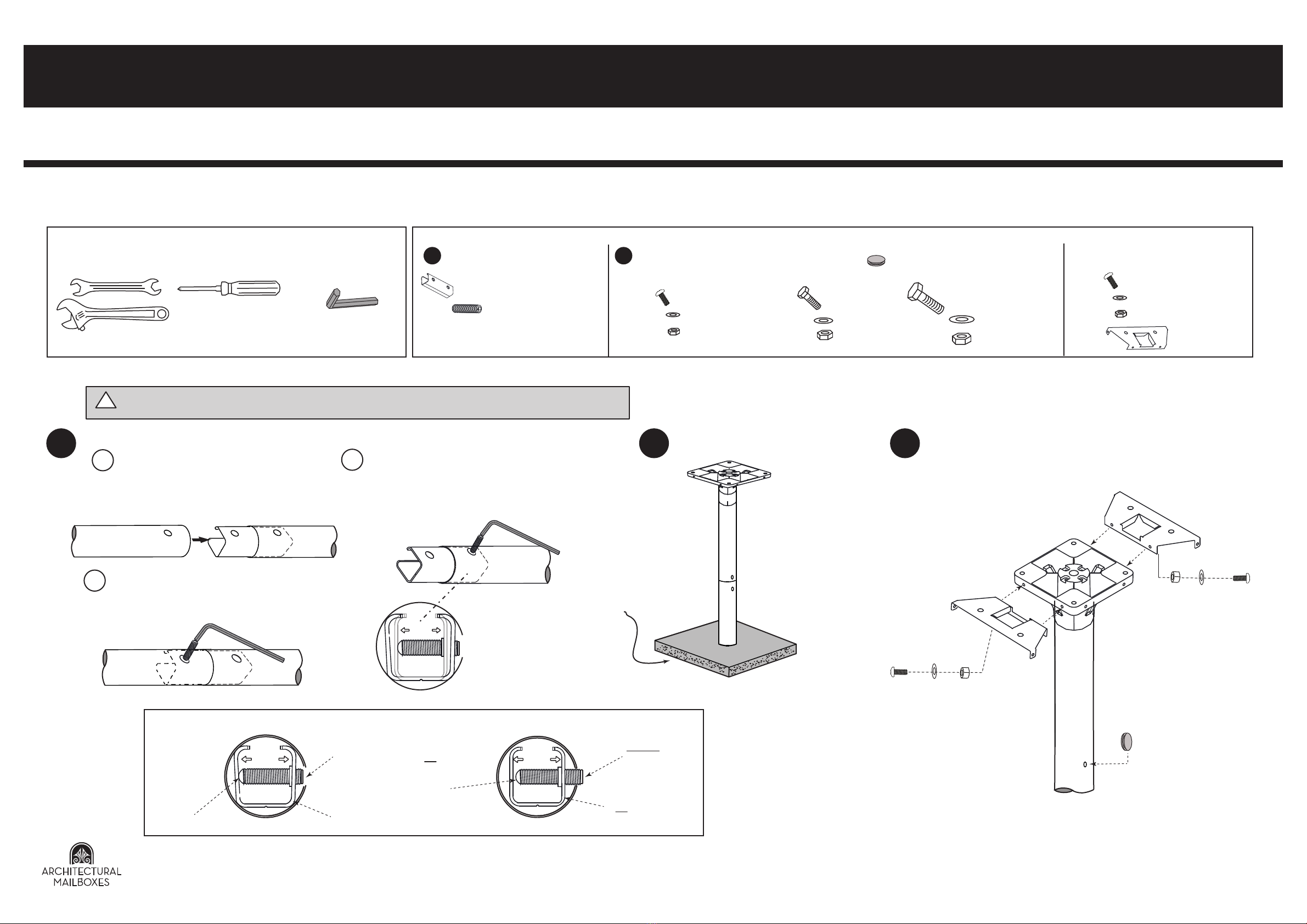
Tools (included)
Hex wrench
1 3
DO NOT install into ground until both post pieces are securely connected using the expansion joiner.
!
If the 4”x10” top hole pattern or the 11.25” side hole pattern
will be used to mount the mailbox, attach the side metal
braces using the 4 Phillips screws, 8 small washers, and 4
small hex nuts.
If the 5”x5” top hole pattern or the 3.75” side hole pattern
will be used to mount the mailbox, do not attach the metal
braces.
Lastly, insert hole plugs to fill the two joint holes.
Phillips screws x4
small washers x8
small hex nuts x4
hole plugs x2
This post is designed for use with
many different mailbox styles. For
larger mailboxes, you may need to
use included braces.
www.architecturalmailboxes.com (800) 464-7491 Rev. F © 2017, Architectural Mailboxes, LLC
R
2
Install the assembled post into
the ground as described in the
instructions for the mailbox. Pay
particular attention to the
location, height, and distance
from the street.
Concrete footing
recommended.
Lay post pieces and the metal expansion
joiner on a flat surface. Then, insert the joiner
into one post piece making sure to align the
screw holes.
Insert the headless set screw into the hole and
tighten with the hex wrench.Tighten the screw
until resistance is felt. Then, tighten at least
another rotation to ensure the joiner is locked in
place as shown in the diagram below.
Correct Post Assembly Incorrect Post Assembly
Set screw
completely
recessed.
a. b.
c. Repeat step 1b to properly assemble the
second post piece, making sure to
minimize the gap between the post
pieces.
Expansion joiner is
making contact with
the post.
Set screw is
making contact
with the
expansion
joiner.
Set screw is
exposed.
Expansion joiner is
not making contact
with the post.
Set screw is
not making
contact with the
expansion
joiner.
x 2, headless set screws
To join the two post pieces:
x 8, large washers
x 4, large hex nuts
x 4, large hex bolts
To attach the mailbox to the plate: To attach the side metal braces:
x 8, small washers
x 4, Phillips screws
x 4, small hex nuts
x 8, small washers
x 4, Phillips screws
x 4, small hex nuts
x 4, hex bolts
x 8, washers
x 4, hex nuts
(For 3.75” and 11.25” side hole patterns) (For 4”x10” top hole pattern)
(For 5”x5” top hole pattern)
x 1, metal expansion joiner
x 2, braces
Hardware (included)
13x 2, hole plugs


