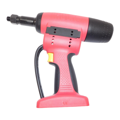
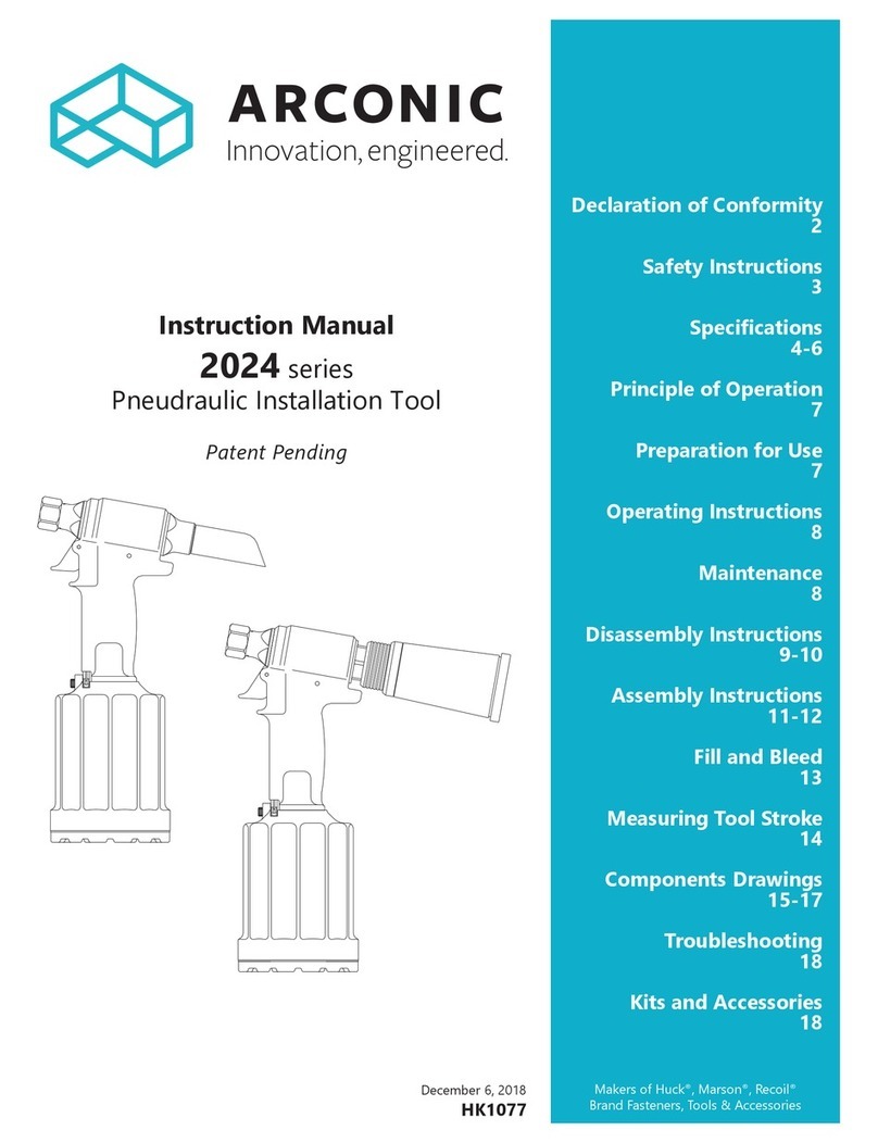
Arconic 2012B User manual

May 4, 2018
HK969
Makers of Huck®, Marson®, Recoil®
Brand Fasteners, Tools & Accessories
Instruction Manual
2012 series
Pneudraulic Installation Tool
Declaration of Conformity
2
Safety Instructions
3
Description
4
Sticker Locations
4
4-5
Principle of Operation
6
Preparation for Use
7
Operating Instructions
8
Maintenance
9
Disassembly Instructions
10-12
Assembly Instructions
13
Fill and Bleed
14-15
Measuring Tool Stroke
16
Components Drawings
17-23
Troubleshooting
24
Kits and Accessories
24

2
2012 series Pneudraulic Installation Tool (HK969)

3
2012 series Pneudraulic Installation Tool (HK969)
I. GENERAL SAFETY RULES:
serious bodily injury.
required, and listed in the manual, are legibly marked on the tool. The
9. Tool is only to be used as stated in this manual. Any other use is
may occur.
before installing the next fastener.
clear from front of tool.
installed.
II. PROJECTILE HAZARDS:
inserted tools or accessories.
5. The risk of others should also be assessed at this time.
front of tool.
III. OPERATING HAZARDS:
3. Hold the tool correctly and be ready to counteract normal or sudden
IV. REPETITIVE MOTION HAZARDS:
body.
discomfort and fatigue.
V. ACCESSORIES HAZARDS:
accessory.
consumables.
VI. WORKPLACE HAZARDS:
2. Proceed with caution while in unfamiliar surroundings; there could be
VII. NOISE HAZARDS:
VIII. VIBRATION HAZARDS:
warm and dry.
IX. PNEUMATIC / PNEUDRAULIC TOOL SAFETY INSTRUCTIONS:
5. Cold air should be directed away from hands.
Safety Instructions
Bold, Italic type, and underline:
instruction.
WARNINGS: Must be understood to avoid
severe personal injury.
CAUTIONS: Show conditions that will damage
equipment or structure.
4
2012 series Pneudraulic Installation Tool (HK969)
Description
The 2012
-04 through -06® fasteners,
-04 through -06®blind
Any other blind fasteners
6.2 bar
MODEL FEATURE
The 2012V model has a Slide & Tube Assembly
124245
the tool.
Specifications
STROKE:1.65 cm
WEIGHT: 20121.99 kg
2012B & 2012V2.13 kg
MAX AIR PRESSURE:6.2 bar
MAX FLOW RATE: 2.9 scfm170 l/min
POWER SOURCE:6.2 bar
MAX OPERATING TEMP:51.7° C
PULL CAPACITY:
11.88 kN @ 6.2 bar
SPEED / CYCLES:
HOSE KITS:
689.5 bar
HYDRAULIC FLUID:
DEXRON®III, DEXRON VI, MERCON®, Allison C-4
ATF
®HFD or
Sticker Locations
These sckers are located at the boom of Cylinder Assembly 125471
and MUST be ordered and placed in these locaons if they become
damaged, lost, or unreadable, or if the Cylinder is replaced.
590350
CE Scker
590351
Max. Pressure
and Flow Scker
590347
HUCK Address
Scker
Figure 13
Where the following trade names are used in this manual, please
note:
DEXRON is a registered trademark of General Motors Corporation.
Loctite is a registered trademark of Henkel Corporation, U.S.A.
LUBRIPLATE is a registered trademark of Fiske Brothers Rening Co.
MERCON is a registered trademark of Ford Motor Corp.
MOLYKOTE is a registered trademark of Dow Corning Corporation
Never-Seez is a registered trademark of Bostik, Inc.
Quintolubric is a registered trademark of Quaker Chemical Corp.
Slic-tite is a registered trademark of LA-CO Industries, Inc.
Spirolox is a registered trademark of Smalley Steel Ring Company
Teon is a registered trademark of E. I. du Pont de Nemours and
Company.
Threadmate is a registered trademark of Parker Intangibles LLC.
TRUARC is a trademark of TRUARC Co. LLC.
Vibra-Tite is a registered trademark of ND Industries, Inc. USA.

5
2012 series Pneudraulic Installation Tool (HK969)
Specifications (continued)
10°
1.1
(2.8)
3.4
(8.6)
0.8
(2.0)
8.7
(22.2)
12.0
(30.5)
4.8
(12.4)
10.3
(26.1)
9.5
(24.2)
2012
2012B
2012V
Ø
3.4
(8.8)
INCHES
(cm)

6
2012 series Pneudraulic Installation Tool (HK969)
Principle of Operation
PULL STROKE
RETURN STROKE
hydraulic system as needed.
Figure 1

7
2012 series Pneudraulic Installation Tool (HK969)
Preparation for Use
The 2012
6.2 bar
170 l/m
NOTEQuick-disconnect ttings and air hoses are not
available for purchase from Huck International, Inc.
Huck includes an air hose (P/N 115436) to facilitate
immediate tool use.
1.
.
2.
connector.
3. Set the 90
6.2 bar, and connect the air hose to the air inlet
connector and to the tool. Press and release the
trigger a few times to cycle the tool.
4.
for the fastener being installed.
5. Connect the air hose to the tool and install fasteners
WARNINGS:
or pintail bottles.
separated pintails may eject forcibly from
rear of tool. Unshielded eyes, especially,
may be permanently injured. Other severe
If there is any chance of a projectile-like
ejection, always point rear of tool in a safe
direction, or be sure there is some structure
that will stop ejecting pintails.
To avoid pinch points, be sure there is
adequate clearance for tool and operator’s
hands before proceeding. Tool moving
between tool and structure if clearance is
limited.
CAUTION: Do not use TEFLON®tape on
pipe threads. Tape can shred and break free
Threadmate®is available in a 4oz. tube from
Huck (P/N 508517).
CAUTION: Insert Pintail Tube (P/N 124448-2)
into tool ONLY when using a nose assembly
that installs either -04 or -05 size fasteners.
Jammed pintails and damage may result
if pintail tube and fastener size do not
correspond correctly.

8
2012 series Pneudraulic Installation Tool (HK969)
Operating Instructions
Read all of these instructions in order to ensure the safe operation of this equipment.
This section details installing Huck Blind Fasteners.
these fasteners. If the tool malfunctions, consult the
NOTEReasonable care of tools by operators is an
important factor in maintaining eciency and
reducing downtime.
TO INSTALL A HUCK BLIND FASTENER:
1.
nose assembly.
NOTEThe tool or nose assembly must be
held against, and at a right angle (90°) to, the
workpiece.
2. Press and hold the trigger until the fastener is
3.
stroke.
next installation cycle.
CAUTIONS:
Fasteners will jam in the nose assembly if
they are pulled when not in a workpiece.
To avoid structural and tooI damage, be
assembly at full stroke.
Remove excess gap from between the sheets
to permit proper fastener installation and
prevent jaw damage. ALL jaw teeth must
engage the pintail to avoid damaging the
teeth.
CAUTION: Ensure the tool has been properly
re-assembled prior to use.
WARNINGS:
Inspect tools for damage and wear before
using. Do not use if damaged or worn; serious
personal injury may occur.
Pulling a pin without a collar, or with collar
chamfer against workpiece, may result in the
pin becoming a high-speed projectile when
the pin grooves are stripped or the pintail
Serious personal injury may occur
includes pin ricochet.
Broken pintails eject from the
speed and force. To reduce the risk of serious
personal injury, be sure the
properly attached and directed away from all
personnel.
Pintail bottles must always be used with
models 2012B and 2012V.
Do not pull on a pin without placing a
fastener in a workpiece. Make sure that the
collar chamfer is out, toward the tool. Pins
eject with great velocity when pintails break
serious injury.
To reduce the risk of serious personal injury,
do not operate tool with a damaged pintail
they are damaged.
Wear approved eye and hearing protection.
Ensure adequate clearance for operator’s
hands before installing fasteners.

9
2012 series Pneudraulic Installation Tool (HK969)
GENERAL
the tool, nose assembly, hoses, trigger and control cord,
and Powerig®
NOTE: Huck tools should be serviced only by
personnel who are thoroughly familiar with its
operation.
and hydraulic systems.
.
them for damage and wear.
in this manual; failure to do so could result in tool
damage.
Spare Parts Service Kit
2012KIT [for 2012], 2012VKIT [for 2012B and
.
®Huck P/N 508567
®Huck P/N
503657505420
25–30 ft.-lbs.
- Smear ®130-AAHuck P/N 502723
®505476rings and
®508517
DAILY
The 2012 series requires a minimum amount of
the tool. NOTE: If the tool is in continuous use, add
a few drops of oil in every 2–3 hours.
- Before connecting an air hose to the tool, clear the air
lines of dirt and water.
necessary.
damage.
Clean
jaws soak; dry them immediately after cleaning. Huck
WEEKLY
- Disassemble, clean, and re-assemble nose assembly in
.
and .
Maintenance
CAUTIONS:
Replace all seals, wipers, and rings when the
tool is disassembled for any reason, and at
regular intervals, depending on severity and
duration of use.
Do not use TEFLON®tape on pipe threads.
Tape can shred resulting in tool malfunction.
Slic-tite®is available in stick form (Huck P/N
503237).
CAUTION: Damaged jaw teeth, or debris
packed between teeth, will result in failure
to install fastener or improperly installed
fastener.

10
2012 series Pneudraulic Installation Tool (HK969)
Disassembly
see Figures 7–10B.
1. Disconnect the tool from the air source.
into a container. Tool can be cycled to clear more
4. Model 2012
5.
throttle arm. Disconnect the ball end of the cable
assembly from the throttle arm
.
8. Screw the button-head screws into the cylinder head,
head.
NOTEAir Piston and rod should not be
disassembled and reassembled. If the locknut
loosens, apply Loctite 271-05; tighten to 25–30
ft.-lbs.
10.
gland with a 1-3/8” socket wrench and extension.
11.
12. Lift the cylinder from the handle/head.
13.
.
NOTEThe throttle valve bushings do not typically
require service.
ended brass rods at least six inches long. With
rod.
16. Model 2012
Models 2012B and 2012V
continued...
WARNING: Disconnect the air hose from the
tool before:
- Removing or attaching the nose assembly
- Performing maintenance on the tool or
nose assembly
- Replacing tool components
The tool may be activated if it is connected
and the cylinder is under pressure; serious
personal injury could result.
CAUTION: Always use a soft-jaw vise to
avoid damaging the tool.
CAUTION: Do NOT scratch, nick, or ding
piston rod. This will cause permanent
hydraulic leakage.
CAUTION: The bushings in the cylinder must
be replaced only if new throttle valve seals
cannot correct an air leak.
Send the unit to an authorized repair center
to have the bushings replaced.

11
2012 series Pneudraulic Installation Tool (HK969)
Disassembly (continued)
PISTON ASSEMBLY AND FRONT GLAND ASSEMBLY
REMOVAL
1. 121694-202
into the Handle/head.
123112-2
123111-2
.
Polyseal Insertion Tool.
NOTEInspect the piston for wear, scoring, and
damage. Replace if necessary.
5. 123761
the cable from trigger.
re-usable
a clean, dry area.
CAUTION:
If piston and gland seals must be reused:
during disassembly, install the Polyseal
Insertion Tool (P/N 121694-202) in rear of
handle to prevent damage to seals.
Take care to not scratch the piston, rod, or
cylinder when removing.
Figure 2
NOTE: The Piston Assembly
shown below (P/N 123774)
is for illustrative purposes;
Piston Assemblies dier
between models.

12
2012 series Pneudraulic Installation Tool (HK969)
Disassembly (continued)
1
2
3
4
5
8
7
6
Figure 3
2012V
2. Secure the head/handle in a
until the retaining-ring holes
each through the
bottle window with
502857
2012V
O-ring from the side
on the bottle side of the
O-ring.
2012V
Special Disassembly Instructions for 2012B &2012V

13
2012 series Pneudraulic Installation Tool (HK969)
Assembly
BEFORE RE-ASSEMBLING THE TOOL:
necessary.
from
2012KIT or 2012VKIT
care not to damage rings.
Smear ®130-AAHuck P/N 502723
®505476rings and
TO RE-ASSEMBLE THE TOOL:
1. If the bushings were removed from the cylinder:
NOTE: Note the
orientation of the Polyseal in Figure 7.
121694-202
into the handle/head. Thread the Piston Assembly
123111-4
soft mallet and wood or brass drift.
Insertion Tool.
8. Model 2012
Models 2012B and 2012V
in the
section.
assembly. Position assembled trigger in handle and
10. Secure the handle assembly soft-
orientation.
assembly. Screw the gland assembly into the handle/
torque to 36–66 ft.-lbs.
installation of the cylinder head assembly.
14. Secure the head
cylinder head squarely into the cylinder, taking care
not to damage O-ring. Install the retaining ring; align
head. Position the gasket on the cylinder assembly,
1/8” hex key.
18. Place the ball end of the cable assembly in the
end of throttle arm. Slide throttle arm into slot on
cylinder.
throttle arm.
hydraulic
section. NOTE: Install the bleed plug and O-ring
assembly after that process.
CAUTION: Replace all seals, wipers, and
rings of disassembled components. These
parts wear out over time, and replacement
minimizes problems such as leaks.

14
2012 series Pneudraulic Installation Tool (HK969)
Fill and Bleed
For
Figures 4–4.
REQUIRED EQUIPMENT
DEXRON® for
Air regulator
NOTE:
The stall nut is used to load the tool during bleeding
and for measuring tool stroke.
PREPARATION
Install air regulator in the air
1.4–2.8 bar
TO BLEED AND FILL THE TOOL:
the bottom of air cylinder; then disconnect. Lay the
tool on its side with
2.
.
NOTE: Rock tool
to free trapped air. Do not allow air to re-enter
at a right angle (90°) to it (Figure 4b) to prevent
drawing in air.
the
tool stroke. NOTE: There are two procedures for
measuring tool stroke: with and without a stall
nut. See . If the tool stroke
is less than the recommended minimum length,
continued...
WARNING: Avoid contact with hydraulic
accordance with local regulations. See MSDS
Figure 4
Figure 4a
CAUTION
recommended in .
Figure 4b
WARNINGS:
Air pressure must be at 20–40 psi (1.4–2.8
bar) to prevent possible injury from high-
pressure spray.
Never cycle the tool without:
B
Fill bottle securely attached to the tool, or
Fill port is held over a container. (Figure 4a)
When not properly contained, any uid in the
tool will spray out. Severe injury may result.

15
2012 series Pneudraulic Installation Tool (HK969)
NOTE: This usually requires 3 or 4 repetitions.
b. Install two fasteners to check function and
to load
c. Re-measure the stroke.
at the minimum requirement length.
BLEED PROCEDURE FOR PARTIALLY FILLED TOOL
IN FIELD USE
1. Disconnect the tool from the Lay tool on
its side with .
3.
times to
5.
1.4–2.8 bar
at a right
angle °to the tool, and cycle the tool 20–30
7.
When the trigger is released,
the the
the tool from the
9.
tool stroke. NOTE: There are two procedures for
measuring tool stroke: with and without a stall
nut. See .
If the tool stroke is less than the recommended minimum
The
cycled. NOTEThis usually requires 3 or 4 repetitions.
b. Install two fasteners to check function and
c. Re-measure the stroke.
the recommended minimum length.
WARNINGS:
Air pressure must be at 20–40 psi (1.4–2.8
bar) to prevent possible injury from high-
pressure spray.
Never cycle the tool without:
B
Fill bottle securely attached to the tool, or
Fill port is held over a container. (Figure 4a)
When not properly contained, any uid in the
tool will spray out. Severe injury may result.
Fill and Bleed (continued)

16
2012 series Pneudraulic Installation Tool (HK969)
Measuring Tool Stroke
Figure 6
WITH A STALL NUT
1.
the nose assembly.
2. Reconnect the tool to the air-line. Press and hold
Thread the
stall nut
bushing.
3.
4. Measure the Xtool stroke
1.65 cm, follow the
Fill and Bleed.
NOTE: Remove the Nose Assembly from the tool for both of the following procedures.
Figure 5
WITHOUT A STALL NUT
1.
the nose assembly.
2. Reconnect the tool to the air-line. Press and hold
Y
3.
Measure and record the X
4. Subtract Xfrom Y.
Stroke = Y-Xtool stroke
If the stroke is less than 0.6501.65 cm, follow the
Fill and Bleed

17
2012 series Pneudraulic Installation Tool (HK969)
Tool Base (2012, 2012B, 2012V)
130727
Bottom Plate
**
NOTES:
Cylinder Head Assembly 123778-1 includes:
---- Cylinder Head (not sold separately)
500864 O-Ring
Throle Valve Assembly 125472-2 includes:
---- Throle Valve (not sold separately)
507396 O-Ring (qty. 3)
*
* Note orientaon of Wipers and Polyseals.
** When Cylinder Assembly is replaced, sckers
(590350, 590351, and 590347) MUST be
purchased and placed as shown in Figure 13.
Tighten and torque to 36–66 .-lbs.
Figure 7

18
2012 series Pneudraulic Installation Tool (HK969)
Tool Head (2012 & 2012B)
125150
End Cap
506488
Wiper*
124828
Washer
123774
Piston
Assy
500621 Pin
124333-1
Trigger
505496
Dowel Pin
116404-1
Cable
Assembly
123766
Handle
Assembly
2012 Head / Handle
506492
Spring
2
124211
Pintail
Deflector
*Note orientation of
Wipers and
Polyseals.
** WARNING Sticker
MUST be purchased
and placed as shown
any time it becomes
worn, lost, or
damaged or if
Handle/Head is
replaced.
505817
Wiper*
122432
Gland Cap
505818
Polyseal*
501110
Back-up
Ring 500816
O-ring
123775 Front
Gland Assy
506160
Polyseal*
506654
Washer
506653
Retaining
Ring
124448-2
Pintail Tube
3
1
1
506160
Polyseal*
1
123774
Piston
Assy
1
122432
Gland Cap
2
505817
Wiper*
2
2
505818
Polyseal*
2
500816
O-ring
2
123770 End Cap &
Adapter Assembly
130692
Pintail Collector
506628
Washer
501007
Retaining
Ring
506488
Wiper*
124828
Washer
2012B Head / Handle
All components same as
2012 except as shown here.
111795
Retaining Nut
120588 Stop
Notes:
Piston Assembly 123774 includes:
124258 Piston (not sold separately)
506160 Polyseal
506653 Retaining Ring
506654 Washer
Front Gland Assembly 123775 includes:
123757 Front Gland (not sold separately)
122432 Gland Cap
505818 Polyseal
500816 O-Ring
501110 Back-up Ring
505817 Wiper
Pintail to be used ONLY for -04 and
-05 size fasteners.
2
Notes:
Piston Assembly 123774 includes:
124258 Piston (not sold separately)
506160 Polyseal
506653 Retaining Ring
506654 Washer
Front Gland Assembly 123775 includes:
123757 Front Gland (not sold separately)
122432 Gland Cap
505818 Polyseal
500816 O-Ring
501110 Back-up Ring
505817 Wiper
Pintail to be used ONLY for -04 and
-05 size fasteners.
3
Notes:
Piston Assembly 123774 includes:
124258 Piston (not sold separately)
506160 Polyseal
506653 Retaining Ring
506654 Washer
Front Gland Assembly 123775 includes:
123757 Front Gland (not sold separately)
122432 Gland Cap
505818 Polyseal
500816 O-Ring
501110 Back-up Ring
505817 Wiper
Pintail to be used ONLY for -04 and
-05 size fasteners.
1
123761
Adapter
590517
Sticker
590240-1
WARNING
Sticker
Figure 8

19
2012 series Pneudraulic Installation Tool (HK969)
Tool Head (2012V)
506648
Washer
124245 Slide &
Tube Assembly
(shown in “ON”
position)
123577
End Cap
500790
O-ring
500778
O-ring
500790
O-ring 500807
O-ring
506628
Washer
501007
Retaining
Ring
502310
Retaining
Ring
123578 Spacer
506488
Wiper*
124828
Washer
123784
Adapter
123761
Adapter
500621 Pin
124333-1 Trigger
505496 Dowel Pin
116404-1 Cable Assembly 123766
Handle Assembly
130692
Pintail Collector
2012V Head / Handle
506492
Spring
505817
Wiper*
122432
Gland
Cap
505818
Polyseal*
501110
Back-up
Ring 500816
O-ring
123757
Front
Gland
506160
Polyseal*
506654
Washer
506653
Retaining
Ring
*Note orientation
of Wipers and
Polyseals.
123774-1
Piston Assy
Notes:
Piston Assembly 123774-1 includes:
124258-1 Piston (not sold separately)
506160 Polyseal
506653 Retaining Ring
506654 Washer
Front Gland Assembly 123775 includes:
123757 Front Gland (not sold separately)
122432 Gland Cap
505818 Polyseal
500816 O-Ring
501110 Back-up Ring
505817 Wiper
Pintail to be used ONLY for -04 and
-05 size fasteners.
2
Notes:
Piston Assembly 123774-1 includes:
124258-1 Piston (not sold separately)
506160 Polyseal
506653 Retaining Ring
506654 Washer
Front Gland Assembly 123775 includes:
123757 Front Gland (not sold separately)
122432 Gland Cap
505818 Polyseal
500816 O-Ring
501110 Back-up Ring
505817 Wiper
Pintail to be used ONLY for -04 and
-05 size fasteners.
3
Notes:
Piston Assembly 123774-1 includes:
124258-1 Piston (not sold separately)
506160 Polyseal
506653 Retaining Ring
506654 Washer
Front Gland Assembly 123775 includes:
123757 Front Gland (not sold separately)
122432 Gland Cap
505818 Polyseal
500816 O-Ring
501110 Back-up Ring
505817 Wiper
Pintail to be used ONLY for -04 and
-05 size fasteners.
1
2
124448-2
Pintail Tube
3
1
1
506160
Polyseal*
1
123774-1
Piston Assy
1
122432
Gland
Cap
2
2
501110
Back-up
Ring
2
505818
Polyseal*
2
500816
O-ring
2
111795
Retaining Nut
120588 Stop
Figure 9

20
2012 series Pneudraulic Installation Tool (HK969)
Tool Head, Top View (2012)
104293
Bleed Plug Assembly
506576
Plug & Gasket Assembly
125116 Guard 505438 O-ring
Figure 9a
This manual suits for next models
2
Table of contents
Other Arconic Power Tools manuals

Arconic
Arconic 254 User manual

Arconic
Arconic 2580 User manual

Arconic
Arconic BobTail User manual

Arconic
Arconic DT4600 User manual

Arconic
Arconic 2024 Series User manual

Arconic
Arconic 202V User manual

Arconic
Arconic Marson M38980 User manual

Arconic
Arconic 2480 series User manual

Arconic
Arconic 244BT User manual

Arconic
Arconic 2013 series User manual