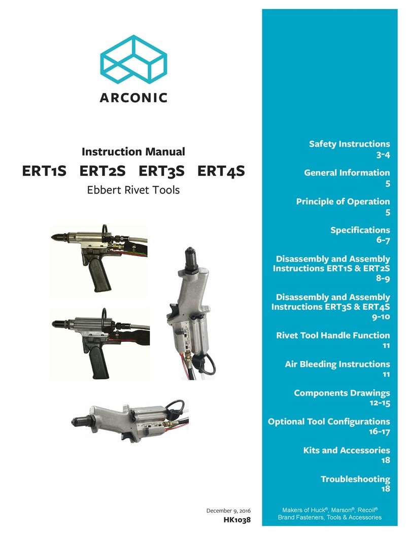
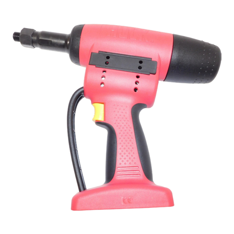
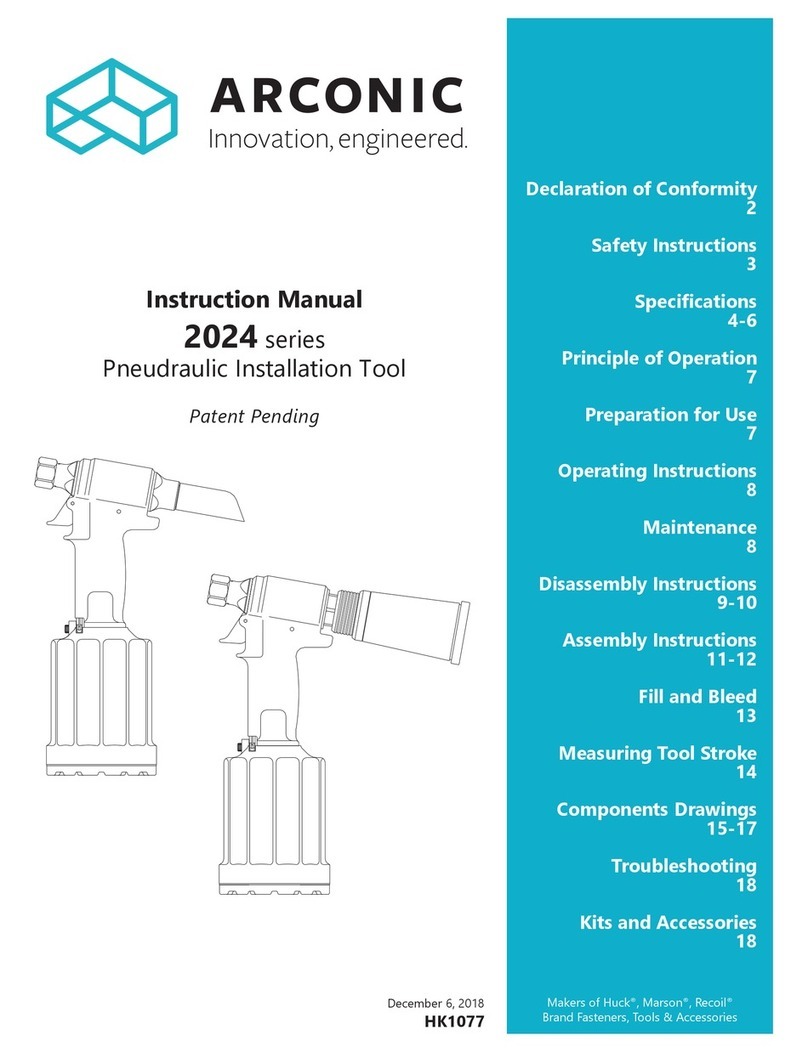
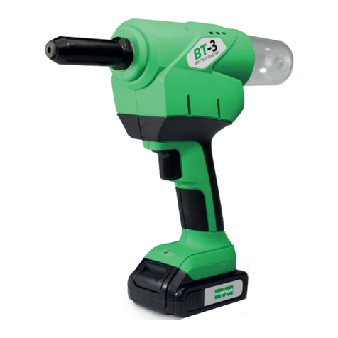
Arconic 254 User manual

Patent Pending
July 31, 2018
HK1172
Instruction Manual
254 and 254OS
Pneudraulic Installation Tools
Declaration of Conformity
2
Safety Instructions
3
4
Principle of Operation
4
Preparation for Use
5
Kits and Accessories
5
Operating Instructions
6
Maintenance
7
Disassembly Procedure
8-9
Assembly Procedure
10
Fill and Bleed Procedure
11
Components Drawings
12-15
Troubleshooting
16
Makers of Huck®, Marson®, Recoil®
Brand Fasteners, Tools & Accessories
Model 254 shown without boot.

2
254 and 254OS Pneudraulic Installation Tools (HK1172)

3
254 and 254OS Pneudraulic Installation Tools (HK1172)
I. GENERAL SAFETY RULES:
serious bodily injury.
required, and listed in the manual, are legibly marked on the tool. The
9. Tool is only to be used as stated in this manual. Any other use is
may occur.
before installing the next fastener.
clear from front of tool.
installed.
II. PROJECTILE HAZARDS:
inserted tools or accessories.
5. The risk of others should also be assessed at this time.
front of tool.
III. OPERATING HAZARDS:
3. Hold the tool correctly and be ready to counteract normal or sudden
IV. REPETITIVE MOTION HAZARDS:
discomfort and fatigue.
V. ACCESSORIES HAZARDS:
accessory.
consumables.
VI. WORKPLACE HAZARDS:
2. Proceed with caution while in unfamiliar surroundings; there could be
VII. NOISE HAZARDS:
VIII. VIBRATION HAZARDS:
warm and dry.
IX. PNEUMATIC / PNEUDRAULIC TOOL SAFETY INSTRUCTIONS:
5. Cold air should be directed away from hands.
Safety Instructions
Bold, Italic type, and underline:
instruction.
WARNINGS: Must be understood to avoid
severe personal injury.
CAUTIONS: Show conditions that will damage
equipment or structure.
4
254 and 254OS Pneudraulic Installation Tools (HK1172)
Specifications
l/min
®
III, DEXRON VI, MERCON®
such as Quintolubric®
will occur.
PULL STROKE
and directed through the center of the
rearward. The attached nose assembly
fastener installation.
RETURN STROKE
Principle of Operation
Where the following trade names are used in this manual, please
note:
DEXRON is a registered trademark of General Motors Corporation.
Loctite is a registered trademark of Henkel Corporation, U.S.A.
LUBRIPLATE is a registered trademark of Fiske Brothers Rening Co.
MERCON is a registered trademark of Ford Motor Corp.
MOLYKOTE is a registered trademark of Dow Corning Corporation
Never-Seez is a registered trademark of Bostik, Inc.
Quintolubric is a registered trademark of Quaker Chemical Corp.
Slic-tite is a registered trademark of LA-CO Industries, Inc.
Spirolox is a registered trademark of Smalley Steel Ring Company
Teon is a registered trademark of E. I. du Pont de Nemours and
Company.
Threadmate is a registered trademark of Parker Intangibles LLC.
TRUARC is a trademark of TRUARC Co. LLC.
Vibra-Tite is a registered trademark of ND Industries, Inc. USA.

5
254 and 254OS Pneudraulic Installation Tools (HK1172)
The 254
6.2 bar
382.28 l/minNOTE: Air quick-
from Huck International, Inc. Huck includes an air
hose (P/N 115436) to facilitate immediate tool use.
.
®, Loctite®567, or Slic-
Tite® to quick-
into the air inlet connector. NOTE: On older nose
assemblies with lock collars, use Loctite®243™ on
collet threads, because the 254 pull piston does
not have staking holes. Refer to the nose assembly
drawings that shipped with nose assemblies.
3. Set the 906.2
bar, and connect the air hose to the tool. Press and
release the trigger a few times to cycle the tool.
nose assembly for the fastener being installed.
7. Connect the air hose to the tool and install fasteners
Preparation for Use
CAUTION: Do not use TEFLON®tape on
pipe threads. Tape can shred, resulting in
malfunctions. Threadmate®is available in a
4oz. tube from Huck (P/N 508517).
Kits &Accessories
KITS
Service Kit 254KIT
etc. Please reference Figures 9-12. Items marked with
254OS.
Assembly Tool Kit 126104
contains Piston Assembly Tool 123111-1, and
ACCESSORIES
Stall Nut - 120824
PSpare Parts Service Kits that cs
and quantitiesy accessible when
using this tool.
Accessorieswhen
maintenance on this tool.

6
254 and 254OS Pneudraulic Installation Tools (HK1172)
TO INSTALL A LOCKBOLT FASTENER:
1.
NOTEIf collar has one tapered end, that end must
be out toward tool; not next to the sheet.
2. in the hole
the collar.
3. Press and hold the trigger until the collar is swaged
4. Release the trigger
stroke.
The re-directed; forward; and
the tool ready for the next
installation cycle.
TO INSTALL A HUCK BLIND FASTENER:
1. Place a
nose assembly.
NOTEThe tool or nose assembly must be
held against,and at a right angle (90°) to, the
workpiece.
2. Press and hold the trigger until the fastener is
installed and the
3. Release the trigger
stroke.
The re-directed; forward; and
the tool ready for the next
installation cycle.
CAUTIONS:
BOM blind fasteners will jam in the nose
assembly if they are pulled when not in
workpiece.
To avoid structural and tooI damage, be
sure there clearance for the nose
assembly at full stroke.
CAUTION: Tool must be properly reassembled
prior to use.
Operating Instructions
FOR SAFE OPERATION, THIS SECTION MUST BE READ AND UNDERSTOOD.
Do NOT pull a
fastener with the
collar upside down.
CORRECT CORRECT
Do NOT install a fastener without a
workpiece (structure to be fastened), a
pin, and a properly oriented collar in place.
WARNINGS:
To avoid severe personal injury, wear approved eye and ear protection.
Be sure of adequate clearance for operator’s hands before proceeding with
fastener installation.
the tool and directed away from all personnel.
Do NOT attempt to install a pin without placing the fastener and collar in the
work piece (structure to be fastened).
Do NOT attempt to install a pin without a properly oriented collar in place.
If these safety measures are not followed, the fastener could eject with great
velocity and cause severe personal injury.
This condition can cause pin to eject with great velocity and force if the
injury.
To avoid pinch point, never place hand between nose assembly and work
piece.
Only use compatible equipment with this tool.
CAUTIONS: Remove
excess gap from between
the sheets. This permits
enough pintail to emerge
from collar for ALL jaw
teeth to engage with
pintail. If ALL teeth do not
engage properly, jaws will
be damaged.
Note: In certain situations,
it may be permissible to
use a BobTail tool and
fastener without a collar
to remove sheet gap prior
to full installation with a
engineering personnel before
attempting this operation.

7
254 and 254OS Pneudraulic Installation Tools (HK1172)
GENERAL
hoses, trigger and control cord, and Powerig®Hydraulic
extend its life. NOTE: This Huck tool should be serviced
only by personnel who are thoroughly familiar with its
operation.
systems.
them for damage and wear.
.
®243 Threadlocker Huck P/N 508567to
®271-05 Huck P/N 503657
to nuts.
Smear ®130-AAHuck P/N 502723
®505476O-rings, Quad-
®, Loctite®567, or Slic-Tite®
DAILY
If a Filter-Regulator-Lubricator unit is not being used,
tool. NOTE: If the tool is in continuous use, add a few
drops of oil in every 2–3 hours.
Before connecting an air hose to the tool, clear the air
lines of dirt and water.
Check the tool and nose assembly for damage and air or
Clean nose assemblies
Clean of ™Jaws in
Do not let jaws soak;
dry them immediately after cleaning. Huck recommends
Periodically, check the tool stroke. If the stroke is short,
WEEKLY
Disassemble, clean, and re-assemble nose assembly in
.
.
Maintenance
CAUTIONS:
Replace all seals, wipers, and rings when the
tool is disassembled for any reason, and at
regular intervals, depending on severity and
length of use.
Do not use TEFLON®tape on pipe threads.
resulting in malfunctions.
CAUTION: Damaged jaw teeth, or debris
packed between teeth, will result in fasteners
not being installed or being improperly
installed.

8
254 and 254OS Pneudraulic Installation Tools (HK1172)
Disassembly
Disassemble only
see Figures 1–4 & 9–11.
1. Disconnect the tool from the air source.
Nose Assembly Data Sheet.
112465
from the glands.
Quad-ring.
If check valve seat is damaged, contact your Huck
representative.
If seat is damaged, it can be removed (through front of
tool head) by using the following procedure. NOTE:
If seat is removed, it cannot be reused; it must be
replaced.
Seat removal: Remove all parts in the reservoir check
valve before removing plug. Unscrew plug, insert a
#10 screw in the thread of plug, and pull to remove.
Use a small drift and hammer and, from the rear
side of the head, drive seat out towards the front of
the head.
Piston
Assembly Tool
NOTEThis will push out the
front and rear gland assemblies, the wiper, and
wiper housing. (Figure 9)
Bleed Plug Assembly
Quad-Ring
Housing
112465 Fill
Tool Assembly
Fill Tool in the
Lock-Out Position
Plug
Screw
Pull Gland Assembly
Return Gland Assy
Handle Assembly
Cylinder Head Assembly
Deflector
Figure 1
WARNING: Disconnect the air hose from the
tool before performing any maintenance.
Serious personal injury could result if the air
hose is connected.
CAUTION: DO NOT scratch the piston or
cylinder when removing.
continued...

9
254 and 254OS Pneudraulic Installation Tools (HK1172)
Disassembly
Piston Assembly
cylinder assemblies.
gland assembly. The handle and cylinder assemblies
in a clean, dry area.
Front Gland
Assembly
close-up
NOTE: Spacer must only be used for disassembly procedure
as it assists in pushing out Front Gland Assembly.
Note orientation
of polyseal
123111-1
AssemblyBullet
123112-1
Spacer HUCK
Figure 2
Muffler
End Cap
Bottom
Exhaust
Gasket
Muffler
O-Ring
Retaining
Ring
Cap Screws
Usethescrewsto
pry out the
cylinder head. Cylinder
Head
Assembly
Press air piston
and piston rod
fullyintotheair
cylinder to aid
in removal of
the intensifier
piston.
Self-locking
Nut
Main Gland
Assembly
Intensifier Piston
Assembly
(Must be unscrewed from
handle-side of piston rod.)
Piston Rod
Air Piston
Assembly
Handle Sleeve
Handle O-ring
Figure 3
CAUTION: DO NOT scratch the piston, rod, or
cylinder when removing.
WARNING: Do NOT re-use seals, wipers, or
rings; irreparable tool damage could occur.
Discard these parts and use replacements.
CAUTION: Always use a soft-jaw vise to avoid
damaging the tool.

10
254 and 254OS Pneudraulic Installation Tools (HK1172)
assembly. Carefully assemble tool without damaging
in handle until it bottoms on the chamfer.
With a 1-3/8 inch socket wrench, torque it into the
handle to 75-85 foot lbs.
5.Holding Self-locking Nut with 9/16 socket and extension,
key, and torque to 180-190 in. lbs.
Assembly squarely into air cylinder. Install Retaining Ring.
Place Bottom Exhaust Gasket on air cylinder. Place
Screws using 5/32 hex key.
9.Assemble Trigger, Cable, and Cable Pin, and slide Cable
into Handle. Align hole in Trigger with hole in Handle
10.Slide Throttle Arm onto ball end of throttle cable. Swing
Bushing and Screw to Throttle Arm. Tighten with 5/32
hex key.
14.Assemble Pull Piston with new seals. Lubricate with
NOTE:
head.
screw assemblies into Handle and Cylinder Head.
and Return Glands. Push Gland Assemblies into handle.
Push Head down on glands.
manual.
Assembly
Handle shown
partially
transparent
for clarity.
Chamfers of
sleeve and
handle meet
here
O-ring inside
groove in handle
Sleeve pushed
in from top of
handle
Figure 4
Trigger Pin
Cable Pin
Cable Assembly
Throttle Arm
Guard Screw
(not shown)
Throttle Arm
Spring
Throttle Valve
with 3O-rings
in place
Setscrew
Throttle Arm Guard
Throttle Arm
Bushing and Screw
Figure 5

11
254 and 254OS Pneudraulic Installation Tools (HK1172)
Fill and Bleed
For
Figures 6–8.
REQUIRED EQUIPMENT
DEXRON®
ATF
6.2–6.9 bar
Air regulator
120337
112465
120824
PREPARATION
1.4–2.8 bar
Bottle.
drops below the red line on the reservoir housing; or
when the tool is rebuilt.
TO BLEED AND FILL THE TOOL
3. Screw the retaining/lock nut onto the head assembly,
Tighten to ensure full thread engagement. NOTE: Back
nut. Verify that the hydraulic piston is full-forward
and locked with nut (and, optionally, with stall nut).
at the bottom of the air cylinder; then disconnect. Lay
6. Connect the tool to the air
times; watch for air bubbles
NOTE: Do not allow air to
re-enter the tool. When
bottle as shown in Figure 8
to prevent drawing in air.
tool with stall nut attached and retaining or lock nut
NOTE: This usually requires 3
or 4 repetitions.
fasteners to test function.
WARNING: Avoid contact with hydraulic
accordance with local regulations. See MSDS
CAUTION
recommended in .
(Check Valve port)
Red line indicator
(Shown in LOCK position.)
Figure 7
Fill Bole
shown in
Check
Valve port
Figure 8
WARNING: Air pressure must be set at
20–40 psi (1.4–2.8 bar) to prevent possible
injury from high-pressure spray. If the plug
before cycling the tool.
Figure 6
120337 FIll Bottle Assy

12
254 and 254OS Pneudraulic Installation Tools (HK1172)
254 Tool Head
(Includes O-ring 505438*)
(Note orientation)
(Piston not sold separately)
(Gland not sold separately)
(Note orientation)
(Includes O-ring 505438*)
( - not sold separately)
(Gland not sold separately)
Figure 9

13
254 and 254OS Pneudraulic Installation Tools (HK1172)
254OS Tool Head
Figure 10

14
254 and 254OS Pneudraulic Installation Tools (HK1172)
Tool Base - 254 and 254OS
Figure 11
Tool comes assembled
with this rubber cylinder
130718.

15
254 and 254OS Pneudraulic Installation Tools (HK1172)
Sticker Location and Throttle Valve
SECTION D-D
D
D
* These parts are included in Service Kit 254KIT
Figure 12

16
254 and 254OS Pneudraulic Installation Tools (HK1172)
Troubleshooting
1. Tool fails to operate when trigger is pressed.
a. Air line not connected.
.
2. Tool does not complete fastener installation and
break pintail.
a. .
b. .
. See the
section.
d. Air in hydraulic system. See .
e. Worn or damaged r
3. Pintail stripped and/or swaged collar not ejected.
a. Check for broken or worn jaws in nose assembly.
See Nose Assembly Data Sheet.
b. Check for loose retaining or lock nut.
4. Hydraulic uid exhausts with air or leaks at base
of handle.
.
R
5. Tool has piston drift.
a.
collet. See .
necessary.
6. Hydraulic uid leaks at rear of pull piston.
a.
. R
7. Hydraulic uid leaks at front of pull piston.
a.
.
8. Pull piston will not return.
b. Throttle arm, cable, or trigger binding.
9. Air leaks at air cylinder head.
trouble. NOTE: “Piston drift” is when the air piston is in the down position, but the hydraulic pull piston is not
in the full-forward position. This causes an out-of-sequence condition.

17
254 and 254OS Pneudraulic Installation Tools (HK1172)
Limited Warranties
Limited Lifetime Warranty on BobTail® Tools:
that its BobTail® installation tools manufactured after
12/1/2016 shall be free from defects in materials and
useful lifetime. This warranty does
Two Year Limited Warranty on Installation Tools:
Huck International, Inc. warrants that its installation tools
and Powerig®
December 1, 2016 shall be free from defects in materials
90 Day Limited Warranty on Nose Assemblies and
Accessories:
Huck International, Inc. warrants that its nose assemblies
and accessories shall be free from defects in materials
literature.
Useful lifetime
Tooling, Part(s) and Other Items not manufactured by
Huck:
any loss or damage, directly or indirectly, arising from the
warranty or for any claim for incidental or consequential
damages.
Huck shall not be liable for any loss or damage resulting
Huck Installation Equipment:
without notice.
below.
Eastern

CERTIFIED
MANAGEMENT
SYSTEM
ISO 9001-2015
ISO 14001-2015
© 2018 Huck International, Inc.
Arconic Fastening Systems
Kingston Operations
1 Corporate Drive, Kingston, NY 12401
Tel: 800-431-3091 • Fax: 845-334-7333
www.afshuck.net/us
INDUSTRIAL NORTH AMERICA
Kingston Operations
Tracy Operations
Tracy, CA 95376
Waco Operations
PO Box 8117
Waco, TX 76714-8117
INDUSTRIAL GLOBAL
Kolkata Operations
55/1, Chowringhee Road,
Melbourne Operations
1508 Centre Road
Clayton, Victoria
Australia 3168
São Paulo Operations
Suzhou Operations
58 Yinsheng Road,
215126 China
Telford Operations
England TF3 3BQ
Tokyo Operations
Chiyoda-ku, Tokyo
AEROSPACE NORTH AMERICA
Kingston Operations
Simi Valley Operations
3990A Heritage Oak Court
Simi Valley, CA 93063
AEROSPACE GLOBAL
Aichach Operations
Robert-Bosch Str. 4
Aichach 86551
Germany
Cergy Operations
15 Rue du Petit Albi
F-95611 Cergy Pontoise
France
Hong Kong Operations
27th Floor, 88 Hing Fat Street
Causeway Bay
Arconic Fastening Systems Tooling Support Locations
Huck fasteners and tooling. NOTICE: The
is only for general guidance with regard
and is not intended to create any warranty,
This manual suits for next models
1
Table of contents
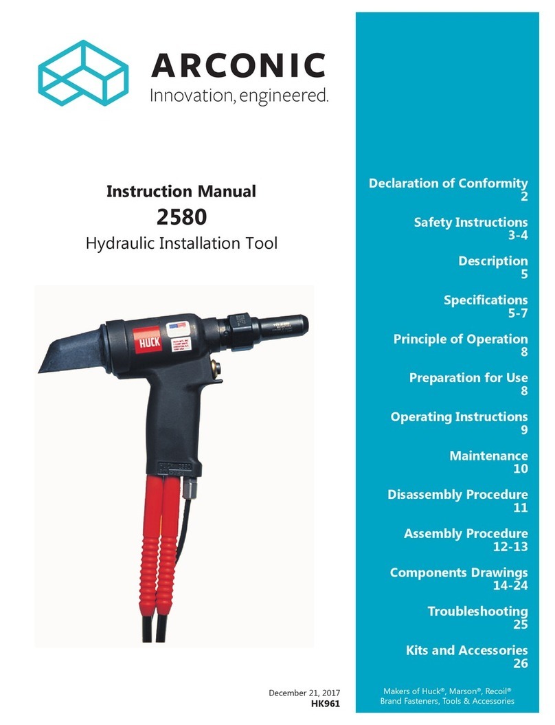
Other Arconic Power Tools manuals

Arconic
Arconic ERT1S User manual

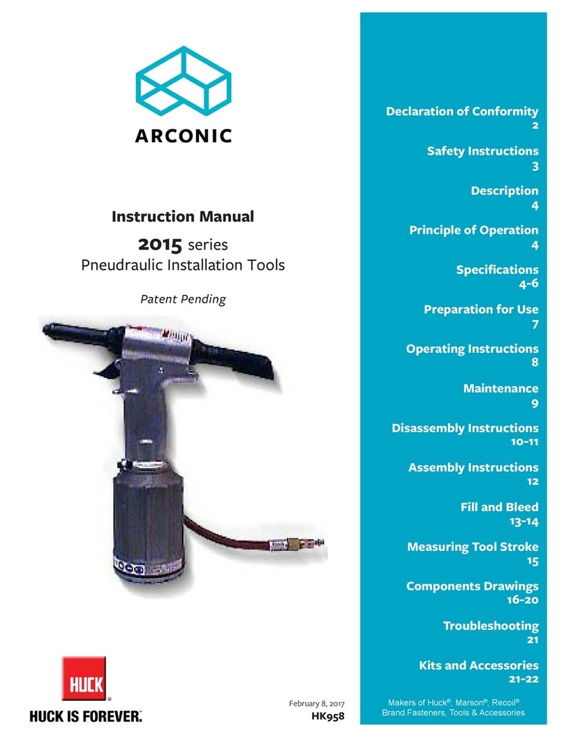
Arconic
Arconic 2015 series User manual

Arconic
Arconic 2480 series User manual

Arconic
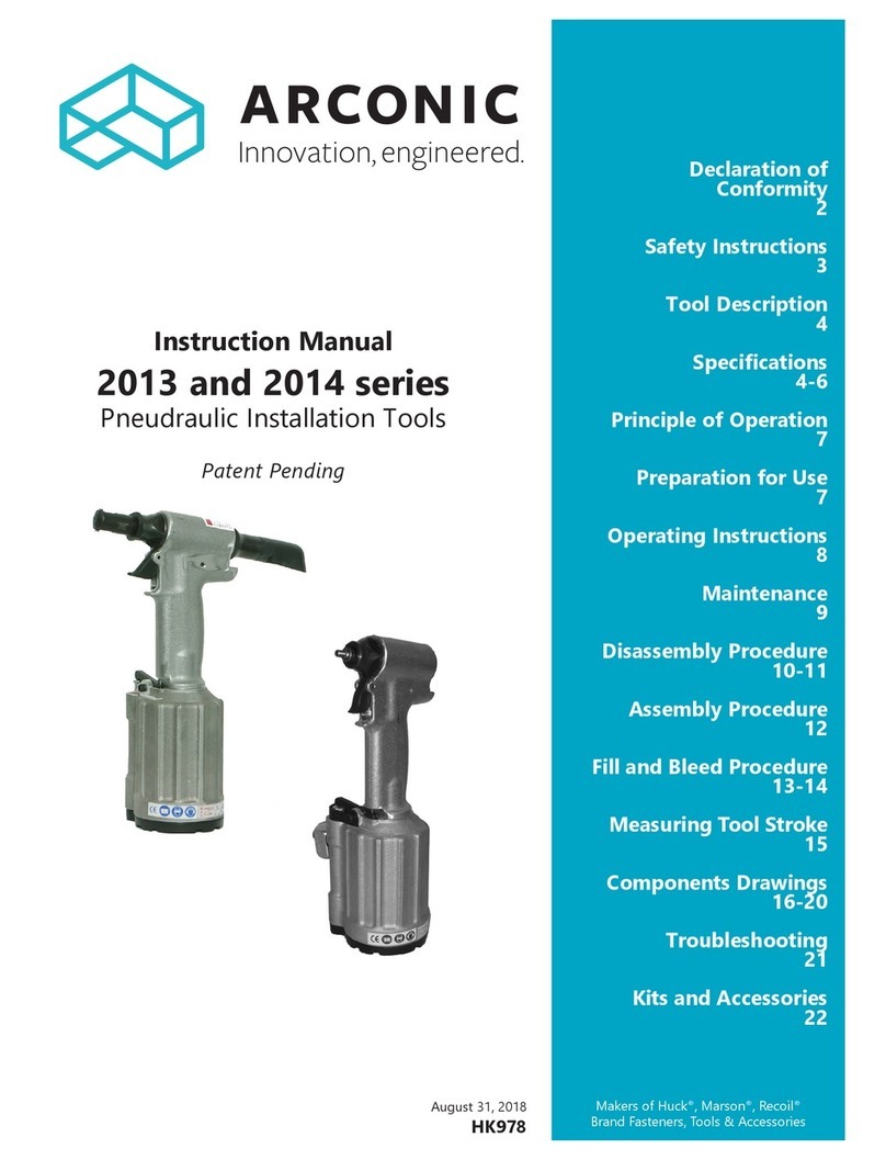
Arconic 2024 Series User manual

Arconic
Arconic 2013 series User manual

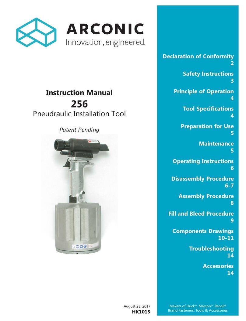
Arconic
Arconic 256 User manual

Arconic
Arconic 2012B User manual

Arconic
Arconic B4600 series User manual

Arconic
Arconic BobTail User manual

Arconic
Arconic Marson M38980 User manual