3
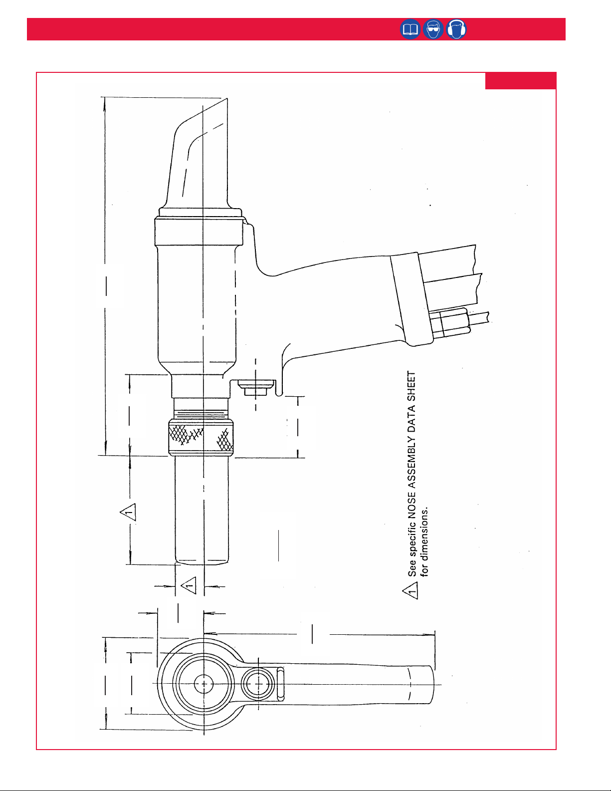
2580 series Hydraulic Installation Tools (HK961)
I. GENERAL SAFETY RULES:
1. A half hour long hands-on training session with
qualied personnel is recommended before using Huck
equipment.
2. Huck equipment must be maintained in a safe working
condition at all times. Tools and hoses should be
inspected at the beginning of each shift/day for
damage or wear. Any repair should be done by a
qualied repairman trained on Huck procedures.
3. For multiple hazards, read and understand the safety
instructions before installing, operating, repairing,
maintaining, changing accessories on, or working near
the assembly power tool. Failure to do so can result in
serious bodily injury.
4. Only qualied and trained operators should install,
adjust or use the assembly power tool.
5. Do not modify this assembly power tool. This can
reduce effectiveness of safety measures and increase
operator risk.
6. Do not discard safety instructions; give them to the
operator.
7. Do not use assembly power tool if it has been
damaged.
8. Tools shall be inspected periodically to verify all ratings
and markings required, and listed in the manual, are
legibly marked on the tool. The employer/operator
shall contact the manufacturer to obtain replacement
marking labels when necessary. Refer to assembly
drawing and parts list for replacement.
9. Tool is only to be used as stated in this manual. Any
other use is prohibited.
10. Read MSDS Specications before servicing the tool.
MSDS specications are available from the product
manufacturer or your Huck representative.
11. Only genuine Huck parts shall be used for replacements
or spares. Use of any other parts can result in tooling
damage or personal injury.
12. Never remove any safety guards or pintail deectors.
13.Never install a fastener in free air. Personal injury from
fastener ejecting may occur.
14. Where applicable, always clear spent pintail out of nose
assembly before installing the next fastener.
15. Check clearance between trigger and work piece to
ensure there is no pinch point when tool is activated.
Remote triggers are available for hydraulic tooling if
pinch point is unavoidable.
16. Do not abuse tool by dropping or using it as a hammer.
Never use hydraulic or air lines as a handle or to bend
or pry the tool. Reasonable care of installation tools
by operators is an important factor in maintaining tool
efciency, eliminating downtime, and preventing an
accident which may cause severe personal injury.
17. Never place hands between nose assembly and work
piece. Keep hands clear from front of tool.
18.Tools with ejector rods should never be cycled with out
nose assembly installed.
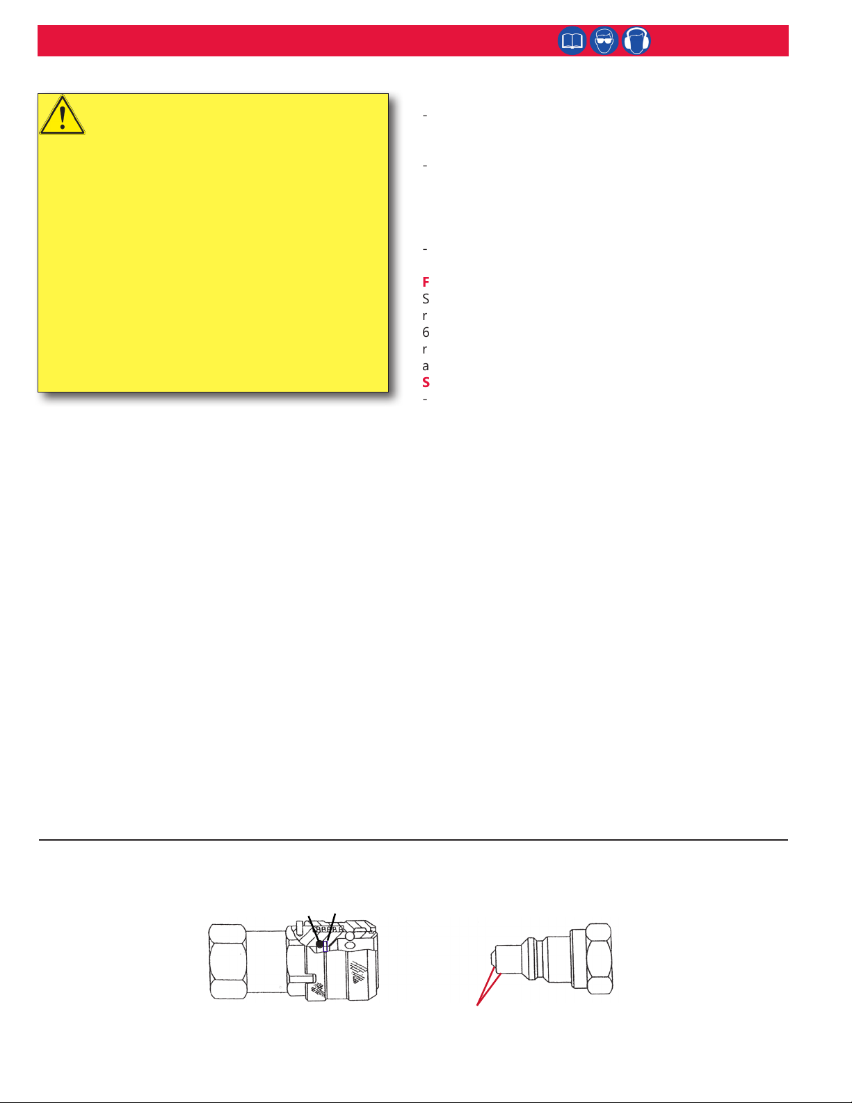
19. When two piece lock bolts are being used always make
sure the collar orientation is correct. See fastener data
sheet for correct positioning.
II. PROJECTILE HAZARDS:
1. Risk of whipping compressed air hose if tool is
pneudraulic or pneumatic.
2. Disconnect the assembly power tool from energy
source when changing inserted tools or accessories.
3. Be aware that failure of the workpiece, accessories,
or the inserted tool itself can generate high velocity
projectiles.
4. Always wear impact resistant eye protection during tool
operation. The grade of protection required should be
assessed for each use.
5. The risk of others should also be assessed at this time.
6. Ensure that the workpiece is securely xed.
7. Check that the means of protection from ejection of
fastener or pintail is in place and operative.
8. There is possibility of forcible ejection of pintails or
spent mandrels from front of tool.
III. OPERATING HAZARDS:
1. Use of tool can expose the operator’s hands to hazards
including: crushing, impacts, cuts, abrasions and heat.
Wear suitable gloves to protect hands.
2. Operators and maintenance personnel shall be
physically able to handle the bulk, weight and power of
the tool.
3. Hold the tool correctly and be ready to counteract
normal or sudden movements with both hands
available.
4. Maintain a balanced body position and secure footing.
5. Release trigger or stop start device in case of
interruption of energy supply.
6. Use only uids and lubricants recommended by the
manufacturer.
7. Avoid unsuitable postures, as it is likely for these not
to allow counteracting of normal or unexpected tool
movement.
8. If the assembly power tool is xed to a suspension
device, make sure that xation is secure.
9. Beware of the risk of crushing or pinching if nose
equipment is not tted.
Continued on next page...
Safety Instructions
GLOSSARY OF TERMS AND SYMBOLS:
- Product complies with requirements set forth by
the relevant European directives.
- Read manual prior to using this equipment.
- Eye protection is required while using this
equipment.
- Hearing protection is required while using this
equipment.
Notes: are reminders of required procedures.
Bold, Italic type, and underline: emphasize a specic
instruction.
WARNINGS: Must be understood to avoid
severe personal injury.
CAUTIONS: Show conditions that will damage
equipment or structure.