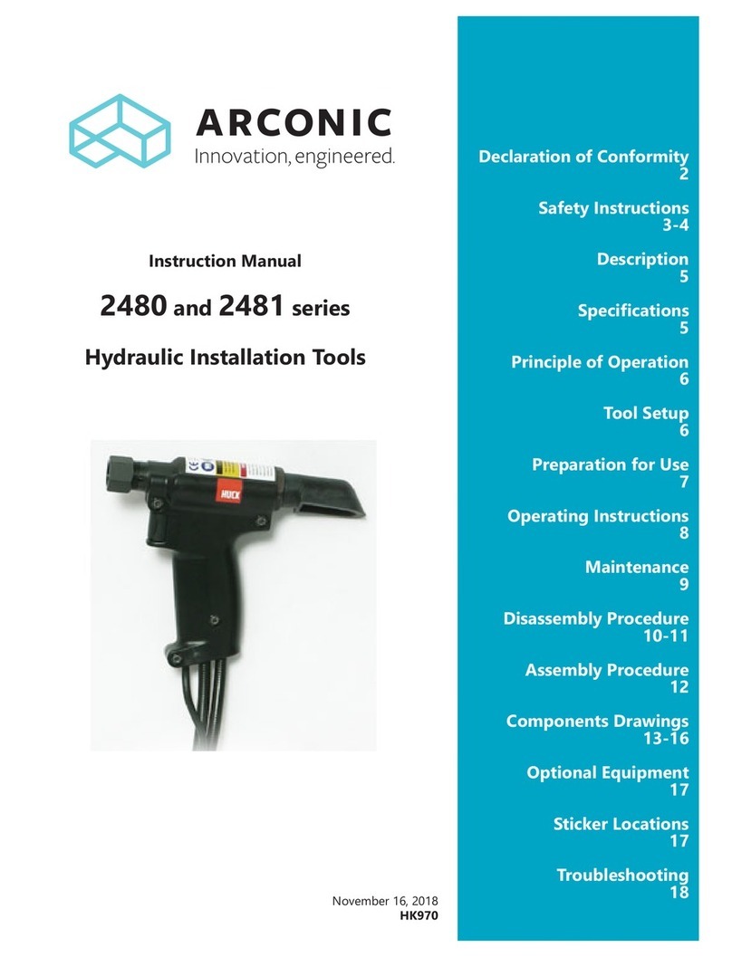
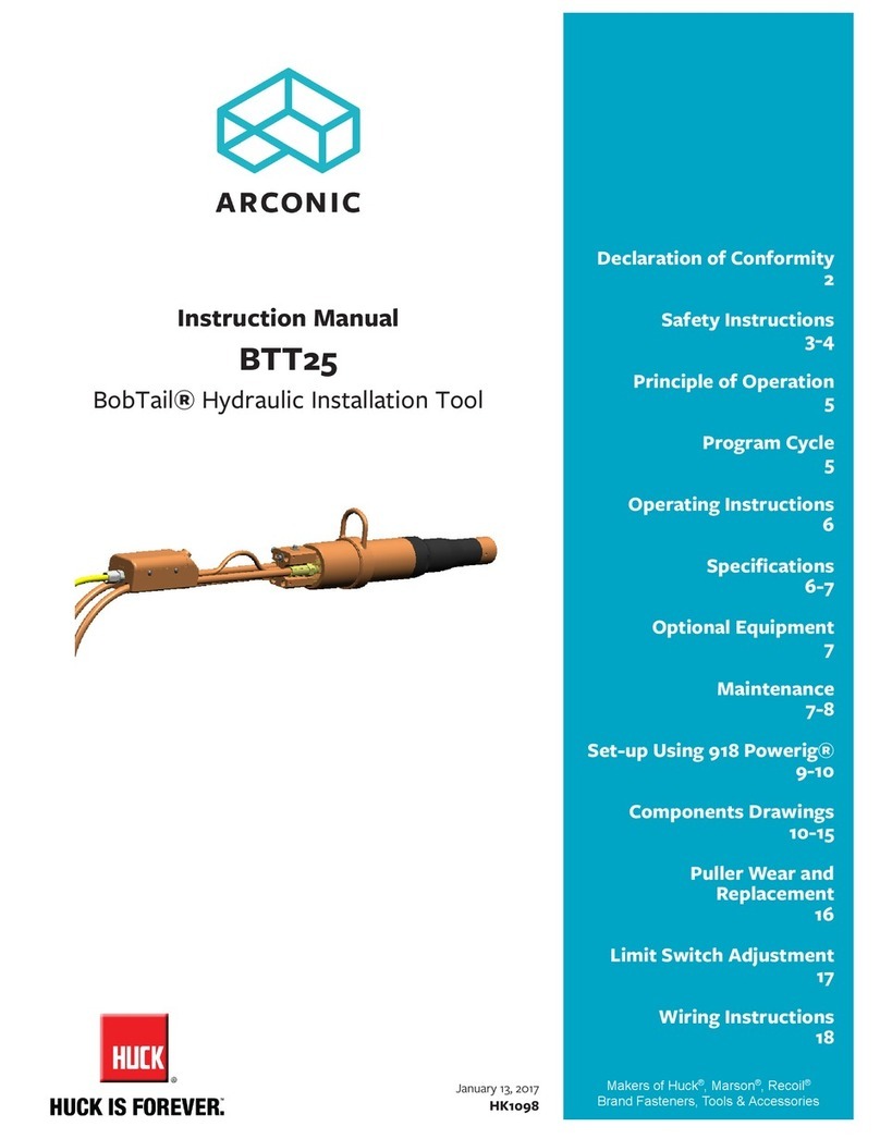
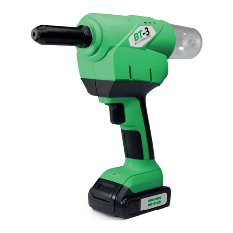
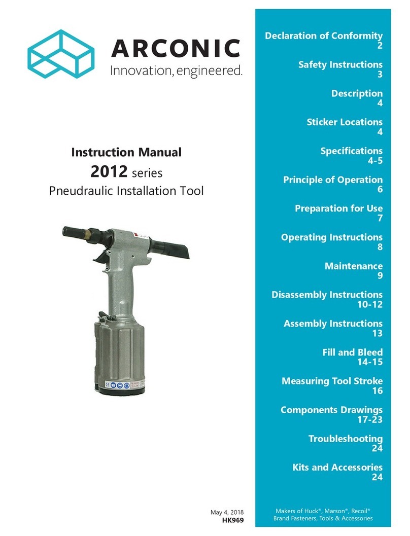
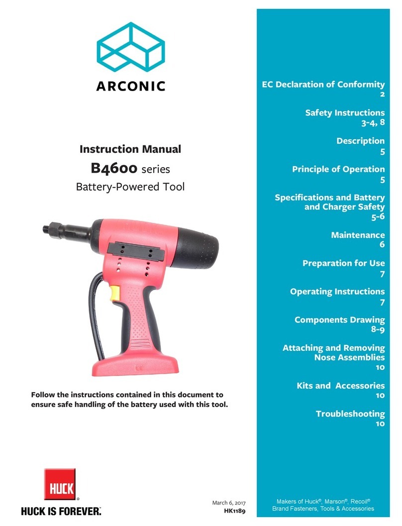
Arconic B1100 Series User manual

Follow the instructions contained in this document
to ensure safe handling of the battery used with
this tool.
November 29, 2017
HK1211
Makers of Huck®, Marson®, Recoil®
Brand Fasteners, Tools & Accessories
Instruction Manual
B1100 series
Battery-Powered Tool
EC Declaration of
Conformity
2
Safety Instructions
3-4, 8
Description
5
Principle of Operation
5
Specications and Battery
and Charger Safety
5-6
Maintenance
6
Preparation for Use
7
Operating Instructions
7
Components Drawing
8
Attaching a Nose Assembly
9
Kits and Accessories
10
Troubleshooting
10

2
B1100 Battery-Powered Tools (HK1211)

3
B1100 Battery-Powered Tools (HK1211)
I. GENERAL SAFETY RULES:
1. A half hour long hands-on training session with
qualied personnel is recommended before using
Huck equipment.
2. Huck equipment must be maintained in a safe
working condition at all times. Tools and hoses
should be inspected at the beginning of each shift/
day for damage or wear. Any repair should be done
by a qualied repairman trained on Huck procedures.
3. For multiple hazards, read and understand the safety
instructions before installing, operating, repairing,
maintaining, changing accessories on, or working
near the assembly power tool. Failure to do so can
result in serious bodily injury.
4. Only qualied and trained operators should install,
adjust or use the assembly power tool.
5. Do not modify this assembly power tool. This can
reduce effectiveness of safety measures and increase
operator risk.
6. Do not discard safety instructions; give them to the
operator.
7. Do not use assembly power tool if it has been
damaged.
8. Tools shall be inspected periodically to verify
all ratings and markings required, and listed in
the manual, are legibly marked on the tool. The
employer/operator shall contact the manufacturer to
obtain replacement marking labels when necessary.
Refer to assembly drawing and parts list for
replacement.
9. Tool is only to be used as stated in this manual. Any
other use is prohibited.
10. Only genuine Huck parts shall be used for
replacements or spares. Use of any other parts can
result in tooling damage or personal injury.
11. Never remove any safety guards or pintail deectors.
12. Check clearance between trigger and work piece to
ensure there is no pinch point when tool is activated.
Remote triggers are available for hydraulic tooling if
pinch point is unavoidable.
13. Do not abuse tool by dropping or using it as a
hammer. Never use hydraulic or air lines as a handle
or to bend or pry the tool. Reasonable care of
installation tools by operators is an important factor
in maintaining tool efciency, eliminating downtime,
and preventing an accident which may cause severe
personal injury.
14. Never place hands between assembly power tool and
work piece. Keep hands clear from front of tool.
II. PROJECTILE HAZARDS:
1. Disconnect the assembly power tool from energy
source when changing inserted tools or accessories.
2. Be aware that failure of the workpiece, accessories,
or the inserted tool itself can generate high velocity
projectiles.
3. Always wear impact resistant eye protection during
tool operation. The grade of protection required
should be assessed for each use.
4. For overhead work, wear a safety helmet.
5. Ensure that the workpiece is securely xed.
6. The risk to others should also be assessed at this
time.
7. Be aware of the risk of being exposed to the ejection
of cuttings or chips.
8. Be aware that working on brittle material can cause
harmful splinters.
III. OPERATING HAZARDS:
1. Use of tool can expose the operator’s hands to
hazards including: crushing, impacts, cuts, abrasions
and heat. Wear suitable gloves to protect hands.
2. Operators and maintenance personnel shall be
physically able to handle the bulk, weight and power
of the tool.
3. Hold the tool correctly and be ready to counteract
normal or sudden movements with both hands
available.
4. Maintain a balanced body position and secure
footing.
5. Release trigger or stop start device in case of
interruption of energy supply.
6. Use only uids and lubricants recommended by the
manufacturer.
7. Avoid direct contact with the inserted tool as it can
become hot.
8. Sharp tools shall always be used.
9. Be aware of risk of whipping compressed air hose.
10. Be aware of risk of cutting with tools with large
dimensions.
IV. REPETITIVE MOTION HAZARDS:
1. When using assembly power tool, the operator can
experience discomfort in the hands, arms, shoulders,
neck or other parts of the body.
2. When using tool, the operator should adopt a
comfortable posture while maintaining a secure
footing and avoid awkward or off balanced postures.
continued
GLOSSARY OF TERMS AND SYMBOLS:
- Product complies with requirements set forth
by the relevant European directives.
- Read manual prior to using this equipment.
- Eye protection is required while using this
equipment.
- Hearing protection is required while using this
equipment.
Notes: are reminders of required procedures.
Bold, Italic type, and underline: emphasize a specic
instruction.
WARNINGS: Must be understood to avoid
severe personal injury.
CAUTIONS: Show conditions that will damage
equipment or structure.
Safety Instructions

4
B1100 Battery-Powered Tools (HK1211)
IV. REPETITIVE MOTION HAZARDS:
1. When using the assembly power tool, the operator
can experience discomfort in the hands, arms,
shoulders, neck or other parts of the body.
2. When using tool, the operator should adopt a
comfortable posture while maintaining a secure
footing and avoid awkward or off balanced postures.
3. The operator should change posture during
extended tasks to help avoid discomfort and fatigue.
4. If the operator experiences symptoms such as
persistent or recurring discomfort, pain, throbbing,
aching, tingling, numbness, burning sensations or
stiffness, these warnings should not be ignored. The
operator should tell the employer and consult a
qualied health professional.
V. ACCESSORIES HAZARDS:
1. Disconnect tool from energy supply before changing
inserted tool or accessory.
2. Use only sizes and types of accessories and
consumables that are recommended. Do not use
other types or sizes of accessories or consumables.
VI. WORKPLACE HAZARDS:
1. Be aware of slippery surfaces caused by use of the
tool and of trip hazards caused by the air line or
hydraulic hose.
2. Proceed with caution while in unfamiliar
surroundings; there could be hidden hazards such as
electricity or other utility lines.
3. The assembly power tool is not intended for use in
potentially explosive environments.
4. Tool is not insulated against contact with electrical
power.
5. Ensure there are no electrical cables, gas pipes, etc.,
which can cause a hazard if damaged by use of the
tool.
VII. DUST AND FUME HAZARDS:
1. Dust and fumes generated when using cutting-off
and crimping power tools can cause ill health; risk
assessment and implementation of appropriate
controls for these hazards are essential.
2. Risk assessment should include dust created by
the use of the tool and the potential for disturbing
existing dust.
3. Operate and maintain the cutting-off or crimping
power tool as recommended in the instruction
handbook, in order to minimize dust or fume
emissions.
4. Direct the exhaust so as to minimize disturbance of
dust in a dust-lled environment.
5. Where dust or fumes are created, the priority shall be
to control them at the point of emission.
6. All integral features or accessories for the collection,
extraction or suppression of airborne dust or fumes
should be correctly used and maintained.
7. Use respiratory protection in accordance with
employer’s instructions and as required by
occupational health and safety regulations.
VIII. NOISE HAZARDS:
1. Exposure to high noise levels can cause permanent,
disabling hearing loss and other problems such
as tinnitus, therefore risk assessment and the
implementation of proper controls is essential.
2. Appropriate controls to reduce the risk may include
actions such as damping materials to prevent
workpiece from ‘ringing’.
3. Use hearing protection in accordance with
employer’s instructions and as required by
occupational health and safety regulations.
4. Operate and maintain tool as recommended in the
instruction handbook to prevent an unnecessary
increase in the noise level.
5. Select, maintain and replace the consumable /
inserted tool as recommended to prevent an
unnecessary increase in noise.
6. If the power tool has a silencer, always ensure that it
is in place and in good working order when the tool
is being operated.
IX. VIBRATION HAZARDS:
1. Exposure to vibration can cause disabling damage to
the nerves and blood supply to the hands and arms.
2. Wear warm clothing when working in cold conditions
and keep hands warm and dry.
3. If numbness, tingling, pain or whitening of the skin
in the ngers or hands, stop using the tool, tell your
employer and consult a physician.
X. ELECTRIC SHOCKS, INJURIES OR FIRE HAZARDS
1. Do not overload the tool; work within the prescribed
work capacity.
2. Never use the tool in humid or wet environment or
close to inammable substances or gases. Risk of
explosion!
3. Ensure that the battery is properly secured in the grip.
4. Remove the battery when the tool is not in use and
when it is undergoing repair or service.
5. Do not use the tool as a hammer.
6. When not in use, keep tool in a dry, closed room and
out of the reach of children.
7. When working with the tool, always wear protective
goggles. Personal protection like clothes, gloves,
safety helmet, non-slip shoes, ear protection and anti-
fall protection are highly recommended.
8. The air inlets for the motor should not be obstructed.
Do not place anything in them.
9. When setting tool down, make sure that it cannot fall.
10. Use only genuine spare parts for repair.
11. Repair work must be carried out by skilled workers, or
send the tool back to the manufacturer.
12. Do not use the tool outside of riveting holes! The
fastener could be ejected from the tool! Never turn
the tool towards yourself or towards another person!
13. The mandrel container must be mounted on the tool
during operation.
Safety Instructions continued
5
B1100 Battery-Powered Tools (HK1211)
DRIVE UNIT: Brushless direct current motor
WEIGHT:
3.9 lbs (1.7 kg) without battery or nose piece
4.4 lbs (2.0 kg) with battery
STROKE: .985 in. (2.5 cm)
PULL CAPACITY: 1100 lb
BATTERY AND CHARGER:
18V battery; 100-240V/50-60Hz charger
Battery rated for 2.1 Ah
Optimum operating temperature range: 50-122°F (10°-
50°C)
Full charging takes approximately 40 minutes. (Charging
times may vary according to the remaining capacity and
the battery temperature.)
One battery can be charged approximately 1000 times.
One fully charged battery will install approximately 500
fasteners. Number of fastener installations may vary based
on the age of the battery and the size and strength of the
fastener.
The tool battery has a display showing battery life in
percent. Press the button in the display to activate the
green LED lights for approx. 5 seconds, and use the table
at right to determine capacity.
Principle of Operation
Description
The B1100 tool is designed to install up to -08
Aluminum BobTail fasteners and is compatible with
standard “L” version noses.
Specially designed for low-volume production
environments, these installation tools are portable,
with no hoses or cords. Batteries are easily replaced
and/or recharged when they have been depleted of
life.
11.22
(28)
2.99
(7.0)
1.06
(2.3) 2.68
(6.8)
11.42
(29)
1.5
(3.8)
4.45
(11.3)
inches
(cm)
3.08
(
7.8
)
2.75
(
6.99
)
The nose assembly is placed over the end of the
fastener until the tool’s anvil bottoms on the fastener.
When the trigger is pressed, the drive unit draws the
collet rearward and breaks the pintail of the fastener
in tension. After the fastener pintail is broken, the
trigger must be released, at which point the drive unit
returns the collet forward. The tool is then ready for
the next fastener.
Specifications
INDICATOR EXPLANATION
Constant
GREEN Battery is fully charged.
Flashing GREEN Battery is charging.
Constant RED Charging temperature error (Battery
too hot or too cold)
Flashing RED Battery is defective, or wrong battery
BATTERY CHARGER FUNCTION LIGHTS
BATTERY FUNCTION LIGHTS
INDICATOR EXPLANATION
Battery is fully charged.
Battery is at 80% capacity.
Battery is at 60% capacity.
Battery is at 40% capacity.
Battery is at 20% capacity.

6
B1100 Battery-Powered Tools (HK1211)
Maintenance
NOTE: As experience dictates, spare components
such as jaws should be kept on hand for repairs.
Keep perishable parts (O-rings and seals) on hand
for replacement whenever the tool is disassembled.
GOOD SERVICE PRACTICES
Regular maintenance will extend the operating
efciency and service life of this tools. For tools that
are used intensively, servicing ahead of schedule is
recommended. Tools should be serviced by personnel
who are thoroughly familiar with them and how they
operate. Service the tool in a clean, well lit area. Give
special care to prevent contamination of pneumatic
and hydraulic systems. Carefully handle all parts and
components. Before reassembly, examine hoses, parts,
and components for damage and wear; replace when
necessary. Disassemble and assemble tool components
in a straight line. Do NOT bend, twist, cock, or apply
undue force. Follow the disassembly and assembly
procedures in this manual. If HUCK recommended
procedures are not followed, the tool could be
damaged. Have available all necessary hand tools
(standard and special); a half-inch brass drift and wood
block; an arbor press; and a soft-jaw vise. Unsuitable
hand tools could cause tool damage.
PREVENTIVE MAINTENANCE
The maintenance of the this blind riveting tool is limited
to the nose assembly and the associated wearing parts:
• Remove battery from the tool.
• Unscrew the retaining nut using at wrench, and
remove the anvil. Clean, and check for and remove
any foreign object debris.
• Unscrew the jaw housing using at wrenches.
• Take out the jaws and follower, and clean them.
Replace the jaws if they are worn.
• Re-assemble in reverse order ensuring that all parts
are tightened.
Regular maintenance will extend the service life of your
high-quality tools. For tools that are used intensively,
servicing ahead of schedule is recommended.
CAUTION: Always replace all seals, wipers,
O-rings, and Back-up rings when the tool is
disassembled for any reason.
Battery and Battery Charger Safety
BATTERY CHARGER SAFETY RULES
• The charger must be used exclusively to charge the
batteries that came with your tool.
• Use only the battery intended for HUCK B4600
battery tool.
• Charge only when environment temperature is
between 23-131°F (-5°C to 55°C) Optimum operating
temperature range: 50-122°F (10°-50°C)
• Store batteries in a dry place with no danger of frost.
• Plug the battery charger in, and gently insert the
battery correctly into the charger. ONLY insert
batteries that are cooled down. The charging
operation starts automatically.
• Do not insert the battery into the charger after each
use.
• If battery life becomes signicantly shorter despite
proper recharging, replace the battery.
• Check the cord, plug and charger regularly and have
them repaired by an authorized, skilled specialist
electrician when damaged.
• For repairs, use only genuine plugs and cords and
genuine spare parts.
• Never use the charger in a humid or wet environment
or close to ammable substance or gases.
• Take the charger out of its packaging before use.
Insert the accompanying battery correctly into the
charger.
• Never try to charge non-rechargeable batteries.
• Store the charger in a dry, closed room, out of the
reach of children.
• Never insert metallic parts into the charging bay -
danger of short circuiting.
• If the charger is wall-mounted, make sure that the
inserted battery cannot fall out due to external
inuences (e.g. vibrations).
• Ensure there is adequate supervision for operators of
this battery charger who may be impaired, untrained,
or unskilled.
BATTERY SAFETY RULES
• Never insert metallic parts into the charging bay -
danger of short circuiting.
• Never try to charge a damaged battery.
• Do not insert a dirty or wet battery into the charger.
• Never throw batteries into the waste, into re, or into
water. If old batteries must be replaced, give used
batteries to an approved battery recycler. NEVER
THROW DISCARDED BATTERIES INTO THE WASTE,
INTO FIRE, OR INTO WATER!
WARNING: To protect against electric
shocks, injuries or re hazards and RISK OF
EXPLOSION, follow all Safety Rules!

7
B1100 Battery-Powered Tools (HK1211)
Operating Instructions
1. Place fastener in workpiece, and position tool over
fastener.
2. Press the tool trigger to begin fastener installation; then
release the trigger when the tool “kicks back”, which is
an indicator of cycle completion. Remove the tool.
3. If tool is adjusted correctly for swaged condition of the
collar, one stroke will install fastener.
The blind riveting tool features optimised operating speed.
After inserting the blind rivet, the blind riveting tool can be
operated in two different modes:
a. Pressing and holding the switch:
Press and hold the switch to start riveting. The pulling
process stops automatically when the rivet reaches the
rear end position. The tool automatically assumes the
front starting position when the switch is released.
b. Tapping the switch:
Riveting is triggered by briey tapping and immediately
releasing the switch. As soon as the mandrel breaks
off, the blind riveting tool stops and automatically re-
assumes the front starting position.
Eject the spent mandrel by tilting to the rear into the spent
mandrel container or to the front through the nose piece.
This tool is equipped with overload protection. In the event
of overload, e.g. by setting fasteners that are outside the
working range, operation stops, indicated by the 3 LEDs
ashing slowly (1 Hz). Press the switch to make the tool go
back to the start position and it will be ready for operation.
The control detects a blockage on return (e.g. dirt, foreign
object, etc. in the anvil assembly). The tool stops the return
procedure and immediately assumes the rear end position
automatically. The fault is indicated by the LEDs ashing
rapidly (2 Hz). The battery pack must be removed and the
fault eliminated. Then reinsert the battery and briey press
the switch. The tool assumes the front end position and is
again ready for use.
This tool is tted with an acoustic warning device, which
provides information about the remaining battery time.
Beeps sound to tell the user when to change the battery.
This ensures that the tool will not switch off during
operation:
3 beeps and ashing LED lights for 10 seconds:
The battery needs to be changed soon (about 20%
battery charge remaining).
6 beeps and ashing LED lights for 10 seconds after
every setting sequence:
Change the battery after a few more riveting sequences
in order to guarantee safe riveting sequences (approx.
10% battery remaining).
9 beeps and ashing LED lights for 10 seconds:
The next riveting sequence cannot be
reliably carried out. The blind riveting tool is switched
off. Change the battery.
WARNING: The tool moves forcibly while
installing fasteners. Be sure there is adequate
clearance for the tool and the operator’s
hands before proceeding. Otherwise, severe
personal injury may result.
CAUTIONS:
Tool must be held perpendicular to the
workpiece.
Tool must be centered on the fastener to
ensure proper installation.
To prevent structural and tool damage, be
sure there is enough clearance for the tool to
move during installation process.
Preparation for Use
1. Remove Battery.
2. Select correct nose assembly for application.
3. Screw in the nose piece and tighten it.
4. Put the battery back in and activate the switch.
WARNINGS:
When operating Huck equipment always wear
approved eye protection. Severe eye injury
may occur if eyes are not protected. The tool
moves forcibly while installing fasteners. Be
sure there is adequate clearance for the tool
and the operator’s hands before proceeding.
Otherwise, severe personal injury may result.
CAUTIONS:
Do not abuse the tool by dropping it,
using it as a hammer, or otherwise causing
unnecessary wear and tear. Reasonable care
of tools by operators is an important factor
in maintaining tool efciency and reducing
downtime.

8
B1100 Battery-Powered Tools (HK1211)
Components Drawing
Screw, short
Bushing
508750
Motor
508742
508741
Motor Control
508743
Pintail Container
508745
508749
Plate
Screw
508738
Wiring
Harness
508748
508736
Screws
Drive Unit
508751
Drive Unit
130944 Nose Adapter Assy
508737
Screws
508736
Screw
111795
Retaining
Nut
Anvil
Adapter
130944-4382-2
Ball Screw Adapter
O-ring

9
B1100 Battery-Powered Tools (HK1211)
Attaching a Nose Assembly
1. Unscrew tool retaining nut.
2. Slide puller cap of nose assembly onto puller; then,
while holding piston rod ats with a wrench, screw
puller and cap onto tool piston until wrench tight.
3. Slide anvil assembly over puller and into tool nose
adapter.
4. Thread retaining nut onto nose adapter and wrench
tight.
99-7932L
Nose Assembly
Anvil Assembly
Puller Cap
Puller

10
B1100 Battery-Powered Tools (HK1211)
Troubleshooting
Kits and Accessories
BATTERY (QUICK-CHANGE): 18.0 V: B-18 BATTERY CHARGER: 100 V-240 V~/50-60 Hz: CH-18-
120-240
1. Tool fails to operate when trigger is pressed:
a. Battery is loose or not connected.
b. Battery is depleted.
2. Pintail stripped and/or swaged collar not ejected
from anvil:
a. Check for broken or worn jaws in nose assembly.
b. Check for worn anvil.
3. Tool overloaded (LED ashes slowly - 1Hz):
a. Check that fastener installation requirements are
within the tool’s work capacity (see page 9).
4. Tool will not return collet to forward position:
a. Check that there is no blockage in the anvil
housing (see page 9).
Always check the simplest possible cause of a malfunction rst. For example, a loose or disconnected trigger line. Then
proceed logically, eliminating each possible cause until the defective part is located. Where possible, substitute known
good parts for suspected defective parts. Use Trouble Shooting Chart as an aid for locating and correcting trouble.

11
B1100 Battery-Powered Tools (HK1211)
Limited Warranties
Limited Lifetime Warranty on BobTail® Tools:
Huck International, Inc. warrants to the original purchaser
that its BobTail® installation tools manufactured after
12/1/2016 shall be free from defects in materials and
workmanship for its useful lifetime. This warranty does
not cover special order / non-standard products, or part
failure due to normal wear, tool abuse or misapplication,
or user non-compliance with the service requirements and
conditions detailed in the product literature.
Two Year Limited Warranty on Installation Tools:
Huck International, Inc. warrants that its installation tools
and Powerigs® manufactured after 12/1/2016 shall be
free from defects in materials and workmanship for a
period of two years from date of purchase by the end
user. This warranty does not cover special order / non-
standard products, or part failure due to normal wear,
tool abuse or misapplication, or user non-compliance with
the service requirements and conditions detailed in the
product literature.
90 Day Limited Warranty on Nose Assemblies and
Accessories:
Huck International, Inc. warrants that its nose assemblies
and accessories shall be free from defects in materials
and workmanship for a period of 90 days from date of
purchase by the end user. This warranty does not cover
special clearance noses, or special order / non-standard
product, or part failure due to normal wear, abuse or
misapplication, or user non-compliance with the service
requirements and conditions detailed in the product
literature.
Useful lifetime is dened as the period over which the
product is expected to last physically, up to the point
when replacement is required due to either normal
in-service wear, or as part of a complete overhaul.
Determination is made on a case-by case basis upon
return of parts to Huck International, Inc. for evaluation.
Tooling, Part(s) and Other Items not manufactured by
Huck:
HUCK makes no warranty with respect to the tooling,
part(s), or other items manufactured by third parties.
HUCK expressly disclaims any warranty expressed
or implied, as to the condition, design, operation,
merchantability, or tness for use of any tool, part(s), or
other items thereof not manufactured by HUCK. HUCK
shall not be liable for any loss or damage, directly or
indirectly, arising from the use of such tooling, part(s),
or other items or breach of warranty or for any claim for
incidental or consequential damages.
Huck shall not be liable for any loss or damage resulting
from delays or non-fulllment of orders owing to strikes,
res, accidents, transportation companies or for any
reason or reasons beyond the control of the Huck or its
suppliers.
Huck Installation Equipment:
Huck International, Inc. reserves the right to make
changes in specications and design and to discontinue
models without notice.
Huck Installation Equipment should be serviced by trained
service technicians only.
Always give the serial number of the equipment when
corresponding or ordering service parts.
Complete repair facilities are maintained by Huck
International, Inc. Please contact one of the ofces listed
below.
Eastern
One Corporate Drive Kingston, New York 12401-0250
Telephone (845) 331-7300 FAX (845) 334-7333
Outside USA and Canada
Contact your nearest Huck International location (see
reverse).
In addition to the above repair facilities, there are
Authorized Tool Service Centers (ATSC’s) located
throughout the United States. These service centers offer
repair services, spare parts, Service Parts Kits, Service
Tool Kits and Nose Assemblies. Please contact your Huck
Representative or the nearest Huck International location
(see reverse) for the ATSC in your area.

Arconic Inc. (NYSE: ARNC) creates breakthrough products that
shape industries. Working in close partnership with our customers,
we solve complex engineering challenges to transform the way we
fly, drive, build and power.
Through the ingenuity of our people and cutting-edge advanced
manufacturing, we deliver these products at a quality and efficiency
that ensures customer success and shareholder value.
Arconic Fastening Systems and Rings world-wide locations:
AMERICAS
Kingston Operations
1 Corporate Drive
Kingston, NY 12401
800-278-4825
845-331-7300
FAX: 845-334-7333
Carson Operations
900 Watson Center Rd.
Carson, CA 90745
800-421-1459
310-830-8200
FAX: 310-830-1436
Waco Operations
PO Box 8117
8001 Imperial Drive
Waco, TX 76714-8117
800-388-4825
254-776-2000
FAX: 254-751-5259
Tucson Operations
3724 East Columbia
Tucson, AZ 85714
800-234-4825
520-747-9898
FAX: 520-748-2142
Acuña Operations
Hidalgo #120
Parque Industrial Amistad
26220 Acuña Coahuila
Mexico
FAX: 525-515-1776
TELEX: 1173530 LUKSME
EUROPE
Telford Operations
Unit C, Stafford Park 7
Telford, Shropshire
England TF3 3BQ
01952-290011
FAX: 0952-290459
Us Operations
BP4
Clos D’Asseville
95450 Us par Vigny
France
33-1-30-27-9500
FAX: 33-1-34-66-0600
AUSTRALIA
Melbourne Operations
11508 Centre Road
Clayton, Victoria
Australia 3168
03-764-5500
Toll Free: 008-335-030
FAX: 03-764-5510
Huck is Forever, For the Long Haul, The Future
of Fastening Technology, The Future of Assembly
Technology, The Future of Tooling Technology,
and Tools of Productivity are service marks of
Huck International. Huck provides technical
assistance regarding the use and application of
Huck fasteners and tooling.
NOTICE: The information contained in this
publication is only for general guidance with
regard to properties of the products shown
and/or the means for selecting such products,
and is not intended to create any warranty,
express, implied, or statutory; all warranties are
contained only in Huck’s written quotations,
acknowledgments, and/or purchase orders. It
is recommended that the user secure specific,
up-to-date data and information regarding each
application and/or use of such products.
© 2017 Huck International, Inc. www.afsrhuck.net/us
1 Corporate Drive, Kingston, NY 12401 • Tel: 800-431-3091 • Fax: 845-334-7333
Table of contents
Other Arconic Power Tools manuals

Arconic
Arconic 202V User manual

Arconic
Arconic 256 User manual

Arconic
Arconic ERT1S User manual

Arconic
Arconic 2013 series User manual

Arconic
Arconic BobTail User manual

Arconic
Arconic 2580 User manual

Arconic
Arconic 244BT User manual

Arconic
Arconic 2480 series User manual

Arconic
Arconic Marson M38980 User manual

Arconic
Arconic 2024 Series User manual