arf F4U Corsair .60 User manual

Specifications
Wingspan: ............... 65.25 in (1657mm)
Wing Area: ............. 752 sq in (48.5 sq dm)
Length: .................... 51.5 in (1308mm)
Weight: .................... 7.5–.8.5 lb (3.4 kg–3.85 kg)
ASSEMBLY MANUAL
F4U Corsair .60 ARF
WE GET PEOPLE FLYING
TM
®
Recommended Engines: .61–.75 2-stroke
.91–1.0 4-stroke
Radio: ...................... 5-channel w/6 servos

2
Table of Contents
Table of Contents . . . . . . . . . . . . . . . . . . . . . . . . . . . . . . . . . . . . . . . . . . . . . . . . . . . . . . . . . . . . . . . . . .2
Covering Colors . . . . . . . . . . . . . . . . . . . . . . . . . . . . . . . . . . . . . . . . . . . . . . . . . . . . . . . . . . . . . . . . . . .2
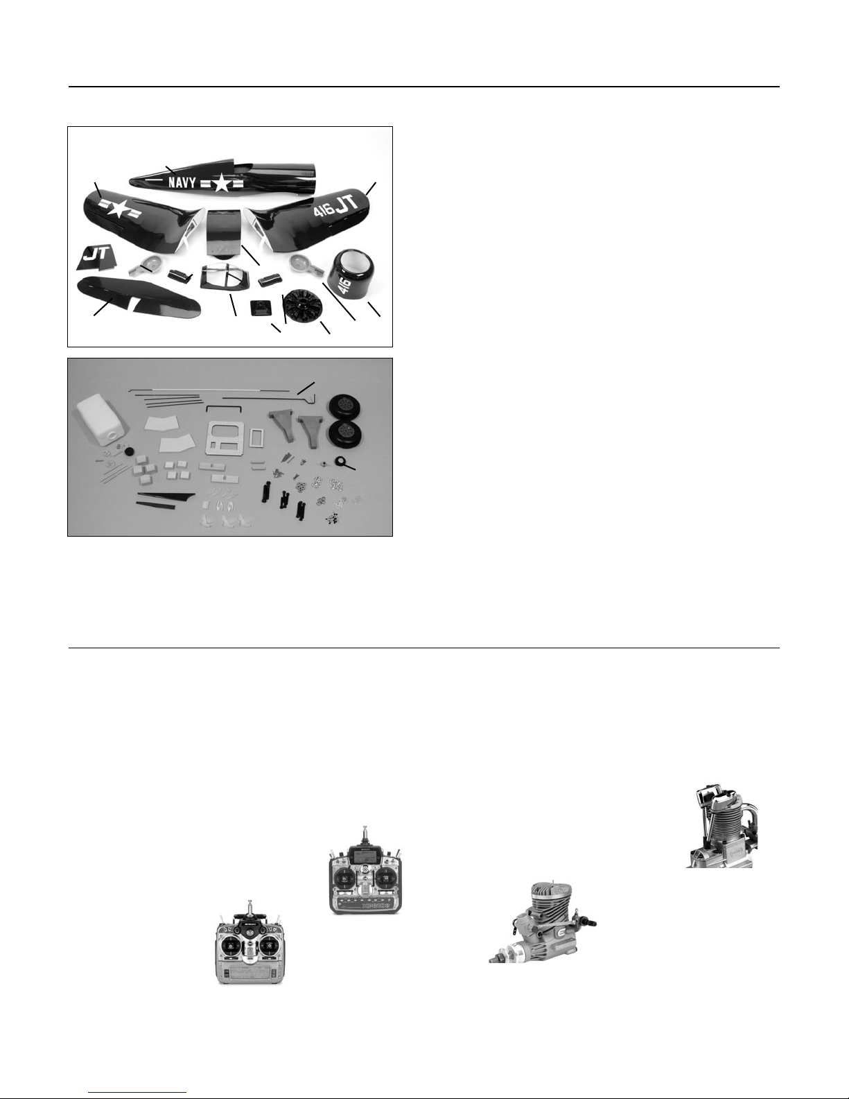
Contents of Kit . . . . . . . . . . . . . . . . . . . . . . . . . . . . . . . . . . . . . . . . . . . . . . . . . . . . . . . . . . . . . . . . . . . .3
Required Radio and Engines . . . . . . . . . . . . . . . . . . . . . . . . . . . . . . . . . . . . . . . . . . . . . . . . . . . . . . . . .3
Additional Required Tools and Adhesives . . . . . . . . . . . . . . . . . . . . . . . . . . . . . . . . . . . . . . . . . . . . . . .4
Other Items Needed (not included in the kit) . . . . . . . . . . . . . . . . . . . . . . . . . . . . . . . . . . . . . . . . . . . . .4
Warning . . . . . . . . . . . . . . . . . . . . . . . . . . . . . . . . . . . . . . . . . . . . . . . . . . . . . . . . . . . . . . . . . . . . . . . . .4
Before Starting Assembly . . . . . . . . . . . . . . . . . . . . . . . . . . . . . . . . . . . . . . . . . . . . . . . . . . . . . . . . . . . .5
Using the Manual . . . . . . . . . . . . . . . . . . . . . . . . . . . . . . . . . . . . . . . . . . . . . . . . . . . . . . . . . . . . . . . . .5
Warranty Information . . . . . . . . . . . . . . . . . . . . . . . . . . . . . . . . . . . . . . . . . . . . . . . . . . . . . . . . . . . . . . .5
Section 1: Joining the Wing Halves . . . . . . . . . . . . . . . . . . . . . . . . . . . . . . . . . . . . . . . . . . . . . . . . . . . .6
Section 2: Attaching the Wing . . . . . . . . . . . . . . . . . . . . . . . . . . . . . . . . . . . . . . . . . . . . . . . . . . . . . . .10
Section 3: Installing the Horizontal Stabilizer . . . . . . . . . . . . . . . . . . . . . . . . . . . . . . . . . . . . . . . . . . .11
Section 4: Installing the Vertical Stabilizer . . . . . . . . . . . . . . . . . . . . . . . . . . . . . . . . . . . . . . . . . . . . . .13
Section 5: Installing the Ailerons . . . . . . . . . . . . . . . . . . . . . . . . . . . . . . . . . . . . . . . . . . . . . . . . . . . . .16
Section 6: Installing the Elevators . . . . . . . . . . . . . . . . . . . . . . . . . . . . . . . . . . . . . . . . . . . . . . . . . . . .17
Section 7: Installing the Rudder . . . . . . . . . . . . . . . . . . . . . . . . . . . . . . . . . . . . . . . . . . . . . . . . . . . . . .19
Section 8: Retract Linkage Installation . . . . . . . . . . . . . . . . . . . . . . . . . . . . . . . . . . . . . . . . . . . . . . . . .22
Section 9: Engine Installation . . . . . . . . . . . . . . . . . . . . . . . . . . . . . . . . . . . . . . . . . . . . . . . . . . . . . . .25
Section 10: Throttle Pushrod Installation . . . . . . . . . . . . . . . . . . . . . . . . . . . . . . . . . . . . . . . . . . . . . . .26
Section 11: Fuel Tank Assembly . . . . . . . . . . . . . . . . . . . . . . . . . . . . . . . . . . . . . . . . . . . . . . . . . . . . .28
Section 12: Fuel Tank Installation . . . . . . . . . . . . . . . . . . . . . . . . . . . . . . . . . . . . . . . . . . . . . . . . . . . .31
Section 13: Radio Installation . . . . . . . . . . . . . . . . . . . . . . . . . . . . . . . . . . . . . . . . . . . . . . . . . . . . . . .32
Section 14: Linkage Installation . . . . . . . . . . . . . . . . . . . . . . . . . . . . . . . . . . . . . . . . . . . . . . . . . . . . . .38
Section 15: Cowling Installation . . . . . . . . . . . . . . . . . . . . . . . . . . . . . . . . . . . . . . . . . . . . . . . . . . . . .44
Section 16: Canopy and Decal Installation . . . . . . . . . . . . . . . . . . . . . . . . . . . . . . . . . . . . . . . . . . . . .47
Adjusting the Engine . . . . . . . . . . . . . . . . . . . . . . . . . . . . . . . . . . . . . . . . . . . . . . . . . . . . . . . . . . . . . .48
Range Testing the Radio . . . . . . . . . . . . . . . . . . . . . . . . . . . . . . . . . . . . . . . . . . . . . . . . . . . . . . . . . . .49
Preflight at the Field . . . . . . . . . . . . . . . . . . . . . . . . . . . . . . . . . . . . . . . . . . . . . . . . . . . . . . . . . . . . . . .49
Control Throws and Center of Gravity . . . . . . . . . . . . . . . . . . . . . . . . . . . . . . . . . . . . . . . . . . . . . . . . .49
2003 Official AMA National Model Aircraft Safety Code . . . . . . . . . . . . . . . . . . . . . . . . . . . . . . . . . . .50
Covering Colors
• Corsair Blue HANU905
• Bright Yellow HANU872

3
Contents of Kit
Large Parts
A. Fuselage HAN2577
B. Wing Set w/Joiner and Ailerons HAN2576
C. Tail Set HAN2578
D. Canopy HAN2586
E. Painted Cowl HAN2579
F. Cockpit w/Radiator HAN2585
G. Wheel Wells HAN2589
H. Dummy Engine HAN2587
Required Radio and Engines
Radio Equipment
• 5-channel radio system (minimum)
• 5 standard servos (JRPS537 recommended
or equivalent)
• 1 low-profile retract servo (JRPS703
recommended or equivalent)
Recommended JR™ Systems
• PCM10X
• XP8103
• X-378
• XP662
• XF631
• XF421EX
Recommended Engines
• .61–.75 2-stroke (EVOE0610 recommended)
(requires BIS04061 Pitts Muffler)
• .91–1.0 4-stroke (SAIE100 recommended)
Small Parts
1. Fuel Tank Assembly HAN2588
2. Engine Mount HAN2033
3. Wheels HAN2584
4. Tail Wheel Assembly HAN2581
5. Pushrod Set HAN2583
Additional items sold separately
Decal Set (not shown) HAN2582
Retract Set HAN2580
JR XP8103
JR PCM 10X
Evolution .61NT
EVOE0610
AB
CDE
1
3
B
F
F
G
C
G
B
2
H
4
4
5
Saito 100 AAC
SAIE100

4
Warning
Additional Required Tools and Adhesives
Tools
• Adjustable wrench
• Canopy Scissors (DYN2517)
• Drill
• Drill Bit: 1/16”, 5/64", 3/32”, 9/64",
5/32", 1/8”, 7/32”
• Foam: 1/2”
• Hex Wrench: 3/16", 9/64" (BON10945 - Set)
• Hobby Knife (XAC3126)
• Phillips screwdriver (small)
• Pliers
• Square (MID1123)
• 11/32" socket wrench
Adhesives
• 6-Minute Epoxy (HAN8000)
• 30-Minute Epoxy (HAN8002)
• Thin CA (cyanoacrylate) Glue (PAAPT08)
• Thick CA (cyanoacrylate) Glue (PAAPT02)
• CA Remover/Debonder (PAAPT16)
• Pacer Z-42 Threadlock (PAAPT42)
• RCZ56 Canopy Glue (ZINJ5007)
• Masking Tape (MMM20901)
Other Required Items
• Epoxy Brushes (DUB345)
• Felt-Tipped Pen (PAR10400)
• File
• Fuel Tubing (AER1003)
• Measuring device (e.g. ruler, tape measure)
• Mixing Sticks for Epoxy (DUB346)
• Paper towels
• Petroleum jelly
• Rubbing alcohol
• Sanding bar
• Sandpaper (medium)
• String
• T-Pins (DUB252)
• Wax paper
An RC aircraft is not a toy! If misused, it can cause serious bodily harm and damage to property. Fly only in open
areas, preferably at AMA (Academy of Model Aeronautics) approved flying sites, following all instructions included
with your radio and engine.
Other Items Needed (not included in the kit)
• Propeller
14x8 - Saito, 12x6 or 13x6 - Evolution
• Safety spinner for engine
HIGSPN008 - Saito, HIGSPN014 - Evolution
• 537 Standard Servo (JRPS537) (5) or equivalent
• 703 Low–Profile Retract Servo (JRPS703)
• Large servo Arm w/Screw (JRPA212)
• 9" Servo Lead Extension (JRPA097) (2)
• 12" Servo Lead Extension (JRPA098) (2)

5
Before Starting Assembly
Using the Manual
Before beginning the assembly of the Corsair, remove each part from its bag for inspection. Closely inspect the
fuselage, wing panels, rudder, and stabilizer for damage. If you find any damaged or missing parts, contact the
place of purchase.
If you find any wrinkles in the covering, use a heat gun or covering iron to remove them. Use caution while
working around areas where the colors overlap to prevent separating the colors.
This manual is divided into sections to help make assembly easier to understand and to provide breaks between
each major section. In addition, check boxes have been placed next to each step to keep track of each step
completed. Steps with two boxes indicate that the step will require repeating, such as for a right or left wing
panel, two servos, etc. Remember to take your time and follow the directions.
Warranty Information
Horizon Hobby, Inc. guarantees this kit to be free from defects in both material and workmanship at the date of
purchase. This warranty does not cover any parts damage by use or modification. In no case shall Horizon Hobby's
liability exceed the original cost of the purchased kit. Further, Horizon Hobby reserves the right to change or modify
this warranty without notice.
In that Horizon Hobby has no control over the final assembly or material used for the final assembly, no liability
shall be assumed nor accepted for any damage of the final user-assembled product. By the act of using the product,
the user accepts all resulting liability.
Once assembly of the model has been started, you must contact Horizon Hobby, Inc. directly regarding any warranty
question that you have. Please do not contact your local hobby shop regarding warranty issues, even if that is where
you purchased it. This will enable Horizon to better answer your questions and service you in the event that you may
need any assistance.
If the buyer is not prepared to accept the liability associated with the use of this product, the buyer is advised to
return this kit immediately in new and unused condition to the place of purchase.
Horizon Hobby
4105 Fieldstone Road
Champaign, Illinois 61822
(877) 504-0233
www.horizonhobby.com

6
Section 1: Joining the Wing Halves
Required Parts
• Left and right wing panels • Center wing panel
• Wing joiner (2) • Wing dowels (2)
Required Tools and Adhesives
• Masking tape • 30-minute epoxy
• Epoxy brush • Mixing stick
• Rubbing alcohol • Paper towels
Step 1
Pull the retract linkage to extend the retract. Make a
slight bend in the linkage towards the bottom of the
wing. This will make the alignment of the wire to the
retract servo much easier later.
Step 2
Remove the tape from the string located in the outer
wing panel. Tape the string to the retract linkage so it
can be accessed later.
Note: Do not remove the string from the wing
panel.
Step 3
Draw a centerline on the wing joiner as shown. The
shorter side of the joiner will be inserted into the
outer wing panel.

Section 1: Joining the Wing Halves
7
Step 4
Test the fit of the wing joiner into one of the outer
wing panels. The joiner should slide into the panel
with little resistance up to the line drawn on the
joiner. Lightly sand the joiner as necessary to achieve
a proper fit.
Note: The joiner will be angled towards the
bottom of the wing.
Step 5
Test the fit of the wing joiner into the outer wing
panel. The joiner should slide into the panel with little
resistance up to the line drawn on the joiner. Lightly
sand the joiner as necessary to achieve a proper fit.
Note: The joiner will be angled towards the
bottom of the wing.
Step 6
Use a hobby knife to remove the covering from the
opening in the center panel for the retract servo.
Step 7
Without using any glue, test fit the wing panel and
center panel together using the wing joiner. Guide
the retract linkage into the center panel so it is
visible in the opening for the retract servo. The panels
must fit together without any gaps top or bottom.
If any gaps do exist, use a sanding bar to lightly
sand the root ribs of both panels until the panels fit
together perfectly.
Note: Read through the remaining steps of
this section before mixing any epoxy.

8
Section 1: Joining the Wing Halves
Hint: It is extremely important to use plenty
of epoxy when joining the wing panels. It
will also be helpful to use wax paper under
the wing joint to avoid gluing the wing to
your work surface.
Step 8
Mix approximately 1 ounce of 30-minute epoxy.
Using an epoxy brush, apply a generous
amount of epoxy to the wing joiner cavity of
the outer wing panel.
Step 9
Completely coat the short half of the wing joiner
with epoxy. Be sure to apply epoxy to the top and
bottom of the joiner also. Insert the epoxy-coated
side of the joiner into the outer wing joiner cavity
up to the mark on the joiner. If you have used
enough epoxy, it will ooze out of the cavity as the
joiner is installed. Remove any excess epoxy using
a paper towel and rubbing alcohol.
Step 10
Apply a generous amount of epoxy to the joiner
cavity and root rib of the center wing panel.

Section 1: Joining the Wing Halves
9
Step 11
Apply epoxy to the exposed portion of
the wing joiner.
Step 12
Apply epoxy to root wing rib of both panels.
Step 13
Carefully slide the wing panels together. Apply
enough pressure to firmly seat the two wing panels
together, causing any excess epoxy to ooze out from
between the panels. Use rubbing alcohol and a paper
towel to remove the excess epoxy. Check to make
sure there are no visible gaps between the panels.
Step 14
Use masking tape to securely hold the wing panels
together. Allow the epoxy to fully cure before
continuing to the next section.
Step 15
Repeat Steps 1 through 14 for the remaining
wing panel.
Step 16
Locate the two 1/4" x 11/4" wing dowels. Use 30-
minute epoxy to glue the wing dowels into the center
panel. The dowels should be inserted so that 7/16" of
the dowel is left exposed in front of the leading edge.

10
Section 2: Attaching the Wing
Required Parts
• Assembled wing • Fuselage
• 1/4-20 blind nut (2) • 1/4" washer (2)
• 1/4-20 x 11/2" socket head bolt (2)
Required Tools and Adhesives
• 30-minute epoxy • Pliers
• Hex Wrench: 3/16"
Step 1
Locate the two 1/4-20 blind nuts. Mix a small amount
of 30-minute epoxy and apply it to the barbs of the
blind nut. Use pliers to install the blind nut from the
inside of the fuselage.
Note: Make sure no epoxy gets into the
threads of the blind nut.
Step 2
Use a sharp hobby knife to remove the covering from
the bolt holes on the top of the wing.
Step 3
Use the two 1/4 x 11/2" socket head bolts and 1/4"
washers to attach the wing to the fuselage.
Step 4
Measure the distance between a point centered
at the rear of the fuselage and each wing tip. The
measurement will be equal if the wing is aligned
correctly. If the measurement is not the same,
slightly oval the hole for the wing bolts until an
equal measurement is achieved.
A A'
A=A'

Section 3: Installing the Horizontal Stabilizer
11
Required Parts
• Assembled wing • Fuselage
• Stabilizer • Elevator joiner wire
Required Tools and Adhesives
• Hobby knife • Felt-tipped pen
• Ruler • 30-minute epoxy
Step 1
Slide the stab into the fuselage, making sure the
stabilizer is as far forward as possible. Center the
stab in the opening by measuring the distance from
the fuselage to each tip. The stab is aligned when
both measurements are identical.
Step 2
Check the distance from each stab tip to each
wing tip. These measurements must be equal for
the stab to be aligned.
Step 3
Check to make sure the wing and stabilizer are
parallel. If they are not, lightly sand the opening
in the fuselage for the stab until the stab is
parallel to the wing.
B B'
B=B'
C C'
C=C'

12
Section 3: Installing the Horizontal Stabilizer
Step 4
After verifying the alignment of the stabilizer, use
a felt-tipped pen to trace the outline of the fuselage
on the stab.
Step 5
Remove the stab and use a hobby knife with a new
blade to remove the covering 1/16" inside the lines
just drawn. Use rubbing alcohol and a paper towel to
remove the lines once they are no longer needed.
Note: Use care not to cut into the underlying
wood and weaken the structure. Doing so
could cause the stab to fail in flight, resulting
in the loss of your airplane.
Step 6
Slide the elevator joiner wire into the slot for
the stabilizer. Slide the stabilizer partially back
into the slot.
Step 7
Mix 1/2 ounce of 30-minute epoxy. Apply epoxy
to the top and bottom of the exposed wood of the
stabilizer. Slide the stabilizer the rest of the way
into the slot in the fuselage. Double-check the
alignment to verify it’s correct. Remove any excess
epoxy using a paper towel and rubbing alcohol.
Allow the epoxy to fully cure before continuing.

Section 4: Installing the Vertical Stabilizer
13
Required Parts
• Fuselage assembly • Fin
• Tail wheel wire • Steering control arm
• Tail wheel wire support bracket
Required Tools and Adhesives
• 30-minute epoxy • 6-minute epoxy
• Square • Hobby knife
• Pliers • Ruler
Step 1
Remove the covering from the top of the fuselage for
the vertical fin and from the bottom of the fuselage
for the tail wheel wire.
Step 2
Locate the tail wheel wire. Slide the steering control
arm onto the wire as shown.
Step 3
Test fit the fin to the fuselage. Slide the fin as far
forward in the slot as possible to provide clearance
for the tail wheel wire. Trace the outline of the
fuselage onto the fin using a felt-tipped pen.

14
Section 4: Installing the Vertical Stabilizer
Step 4
Remove the fin and use a hobby knife with a new
blade to remove the covering 1/16" below the lines
just drawn. Use rubbing alcohol and a paper towel to
remove the lines once they are no longer needed.
Note: Use care not to cut into the underlying
wood and weaken the structure. Doing so
could cause the fin to fail in flight, resulting in
the loss of your airplane.
Step 5
Locate the tail wheel wire support bracket and lightly
sand the bracket using medium sandpaper.
Step 6
Cut a slot in the bottom of the aft edge of the fin for
the bracket. The slot must be on the centerline of
the fin (hinge line). Use a small amount of 6-minute
epoxy to glue the bracket into position. Make sure
epoxy does not get into the hole in the bracket.
Step 7
Slide the fin back into the fuselage. Check the
alignment of the fin to the stabilizer using a square.
The fin must be 90 degrees to the stabilizer when
properly aligned. If not, carefully sand the bottom of
the fin to provide the clearance to align the fin.

Section 4: Installing the Vertical Stabilizer
15
Step 8
Mix 1/2 ounce of 30-minute epoxy. Apply the
epoxy to both the exposed wood on the fin and the
slot in the fuselage. Use care not to get epoxy in
the tail wheel wire support bracket. Insert the fin
and use tape to hold the fin in position until the
epoxy fully cures.
Note: Check the alignment of the fin
periodically to make sure it isn't moving
while the epoxy cures.
Step 9
Slide the tail gear wire through the tube inside the
fuselage and through the tail gear wire support
bracket from the bottom of the fuselage. Slide it
in until the distance between the bottom of the
fuselage and bend for the wheel is 17/8".
Step 10
Measure 3/4" up from the fuselage and mark the
tail wheel wire. Position the wire so the tail wheel
will be parallel to the runway. Make a 90-degree
bend in the wire at the mark so the wire will extend
into the rudder.
Step 11
Cut the excess wire so only 1" extends past the rear
edge of the fin.

16
Section 5: Installing the Ailerons
Required Parts
• Wing • CA hinges (6)
• Aileron (left and right)
Required Tools and Adhesives
• Thin CA • T-Pins
Step 1
Locate three CA hinges. Place a T-pin in the center of
each hinge.
Step 2
Place the hinges in the precut slots in the aileron.
The T-pin will rest against the leading edge of the
aileron when installed correctly.
Step 3
Slide the aileron and wing together. The gap between
the leading edge of the aileron and wing should
be a maximum of approximately 1/64". Check to
make sure the gap at both ends of the aileron
are equal and that the aileron can move without
rubbing on the wing.
Note: Do not use CA accelerator during the
hinging process. The CA must be allowed to
soak into the hinge to provide the best bond.
Using accelerator will not provide enough time
for this process.
Step 4
Remove the T-Pins and move the aileron to provide
the best access to the hinge. Apply thin CA to each
hinge. Make sure the hinge is fully saturated with CA.
Use a paper towel and CA remover/debonder to clean
up any excess CA from the wing and/or aileron. Make
sure to apply CA to both sides of the hinges.

Section 5: Installing the Ailerons
17
Step 5
Firmly grasp the wing and aileron and gently pull
on the aileron to ensure the hinges are secure and
cannot be pulled apart. Use caution when gripping
the wing and aileron to avoid crushing the structure.
Step 6
Work the aileron up and down several times to work
in the hinges and check for proper movement.
Step 7
Repeat Steps 1 through 6 for the remaining aileron.
Section 6: Installing the Elevators
Required Parts
• Fuselage assembly • Elevator joiner wire
• CA hinge (6)
• Elevator (left and right)
Required Tools and Adhesives
• Thin CA • T-pins
• 30-minute epoxy • Medium sandpaper
• Drill • Drill Bit: 9/64"
Step 1
Locate one of the elevator halves. Remove the
covering from the slot in the elevator. Measure in 3/4"
from the inside edge of the elevator and drill a 9/64"
hole in the elevator that is 1" deep for the elevator
joiner wire.

18
Section 5: Installing the Ailerons
Step 2
Locate three CA hinges. Place a T-pin in the center of
the hinges. Place the hinges into the elevator half.
Step 3
Test fit the elevator and stab together. The
elevator joiner wire will be inserted into the
hole drilled in Step 1.
Step 4
Mix 1/2 ounce of 30-minute epoxy and apply it to
the groove and hole in the elevator half. Insert the
elevator joiner wire. Remove any excess epoxy
using rubbing alcohol and a paper towel.
Note: You can combine the previous step with
the following step if you like. This will hold
the elevator in position while the epoxy cures.
Step 5
Check to make sure the elevator moves freely. It
should not rub against the stabilizer at the tip.
Check to make sure the hinge gap between the
elevator and stabilizer is roughly 1/64". Apply thin CA
to both sides of the hinge. Make sure to
saturate the hinge and don’t use accelerator.
Step 6
Once the CA and epoxy have fully cured, gently
pull on the elevator and stab to make sure the
hinges are well glued. Flex the elevators a few
times to break in the hinges.

Section 5: Installing the Ailerons
19
Step 7
Hold the remaining elevator in position against the
stabilizer. Mark the location of the elevator joiner
wire onto the elevator.
Step 8
Drill the location marked in the previous step using
a 9/64" drill bit.
Step 9
Repeat Steps 2 through 6 to install the remaining
elevator half.
Section 7: Installing the Rudder
Required Parts
• Fuselage assembly • Rudder
• CA hinge (3)
Required Tools and Adhesives
• Thin CA • T-pins
• 30-minute epoxy • Medium sandpaper
• Drill • Drill Bit: 1/8"
Step 1
Hold the rudder in position against the fin. Mark the
location of the tail wheel wire onto the rudder.

20
Section 7: Installing the Rudder
Step 2
Drill the location marked in the previous step using
a 1/8" drill bit.
Step 3
Use a hobby knife to cut a groove for the tail
wheel wire into the leading edge of the fin from
the hole to the bottom of the rudder. Also cut
a small notch to allow clearance for the tail wheel
wire support bracket.
Step 4
Use medium sandpaper to roughen the portion of the
tail wheel wire that will be inserted in the rudder.
Step 5
Locate two CA hinges and place a T-pin in the center
of each hinge. Place the hinges into the rudder.
Step 6
Test fit the rudder to the fin and tail wheel wire.
The gap between the rudder and fin should be a
maximum of approximately 1/64".
Step 7
Check the movement of the rudder to make sure it
clears the fin.
Step 8
Remove the rudder from the fin. Mix 1/2 ounce of
30-minute epoxy and apply it to the groove and
hole in the rudder. Insert the rudder control rod.
Remove any excess epoxy using rubbing alcohol
and a paper towel.
Note: You can combine the previous step with
the following step if you like. This will hold
the rudder in position while the epoxy cures.
Important: Do not let epoxy get into the tail
wheel wire support bracket.
Step 9
Check to make sure the rudder moves freely. Apply
thin CA to both sides of the hinge. Make sure to
saturate the hinge and don’t use accelerator.
Table of contents
Other arf Toy manuals

arf
arf Composite QQ Yak 54 2.6 m User manual

arf
arf Tornado Owner's manual

arf
arf BO-209 MONSUN Owner's manual

arf
arf Katana User manual

arf
arf AeroPet 50 User manual

arf
arf CORSAR Owner's manual

arf
arf XPower P-51D MUSTANG User manual

arf
arf MINIMOA GLIDER User manual

arf
arf BH67 User manual

arf
arf MX2 50CC V2 User manual
Popular Toy manuals by other brands

Phoenix Model
Phoenix Model Boomerang 60 instruction manual

Crayola
Crayola Double-Sided Artist Easel instruction manual

LEGO
LEGO 44017 Assembly instructions

Fancy Foam Models
Fancy Foam Models EPP 3Decathlon Assembly instructions

Lionel
Lionel SD60 owner's manual

LEGO
LEGO Super Heroes 30301 Instructions for use