arf AT.6-TEXAN Owner's manual

SPECIFICATION
Wingspan : 1,830 mm 72.05 in.
Length : 1,250 mm 49.21 in.
Weight : 3.8 kg 8.36 Lbs.
Radio : 06 channels.
Servo : 08 servos.
Engine : 61 2 stroke.
91 4 stroke.
Instruction Manual book
MadeinVietnam.

AT.6-TEXAN - ITEM CODE: BH75.Instruction Manual
2
This instruction manual is designed to help you build a great flying aeroplane. Please read this
manual thoroughly before starting assembly of your AT.6 TEXAN. Use the parts listing below to
identify all parts.
WARNING
Please be aware that this aeroplane is not a toy and if assembled or used incorrectly it is
capable of causing injury to people or property. WHEN YOU FLY THIS AEROPLANE YOU
ASSUME ALL RISK & RESPONSIBILITY.
IfyouareinexperiencedwithbasicR/CflightwestronglyrecommendyoucontactyourR/Csupplier
and join your local R/C Model Flying Club. R/C Model Flying Clubs offer a variety of training
proceduresdesignedtohelpthenew pilotonhiswaytosuccessfulR/C flight.Theywillalso beable
to advise on any insurance and safety regulations that may apply.
TOOLS & SUPPLIES NEEDED
Thick cyanoacrylate glue.
30 minute epoxy.
5 minute epoxy.
Hand or electric drill.
Assorted drill bits.
Modellingknife.
Straight edge ruler.
2mm ball driver.
Phillips head screwdriver.
220 grit sandpaper.
90° square or builder’s triangle.
Wire cutters.
Masking tape & T-pins.
Thread-lock.
Paper towels.
Some more parts.
HARDWAREPACK
COWLING.
Landinggear.....
Toavoid scratching yournew airplane,donot
unwrap the pieces until they are needed for
assembly. Cover your workbench with an old
towel or brown paper, both to protect the
aircraftand toprotect thetable. Keepa couple
of jars or bowls handy to hold the small parts
after you open the bag.
Pleasetrialfitalltheparts. Makesureyouhave
the correct parts and that they fit and are
alignedproperly beforegluing!Thiswillassure
proper assembly. AT.6 TEXAN ARF is hand
made from natural materials, every plane is
unique and minor adjustments may have to
be made. However, you should find the fit su-
perior and assembly simple.
The painted and plastic parts used in this kit
are fuel proof. However, they are not tolerant
of many harsh chemicals including the
following: paint thinner, C/A glue accelerator,
C/A glue debonder and acetone. Do not let
these chemicals come in contact with the
colors on the covering and the plastic parts.
PARTS LISTING
FUSELAGE ASSEMBLY
(1) Fuselage.
WING ASSEMBLY
(1) Right wing half with pre-installed
aileron.
(1) Left wing half with pre-installed
aileron.
Tail section assembly
(1) Vertical stabilizer with pre-
installedrudder.
(1) Horizontal stabilizer with pre-
installedelevator halves.
SUGGESTION
NOTE.

AT.6-TEXAN - ITEM CODE: BH75 INSTRUCTION MANUAL
3
Caution: this model is not a toy!
If you are a beginner to this type of powered
model,please askan experiencedmodelflyer
forhelp andsupport.Ifyouattempttooperate
themodel withoutknowingwhat youaredoing
you could easily injure yourself or somebody
else. Please keep your safety and well-being
in mind at all times.
Important: before you start construction
Evenifyou havealready built alarge number
ofRC modelspleaseread rightthrough these
instructions and check all the kit components
against the parts list. We have taken great
trouble to keep construction as simple as
possible, without making any compromises
in the area of safety.
Note regarding the film covering
Minor creases or bubbles may develop in the
film covering due to major fluctuations in
weather conditions (temperature, humidity
etc.); in rare cases you may even find a slight
warp in a component. These minor faults are
in the nature of film-covered built-up wooden
structures, and can easily be corrected using
a heat gun, as commonly used for modelling.
Creases: Blowwarm airoverthearea
and rub down with a soft
cloth.
Wing warp: Hold the panel twisted
gently in the opposite
direction to the warp, and
apply warm air to remove
the creases from the
covering.
Caution! do not heat the film more than is
absolutely necessary. If the air or the iron is
too hot, the film may melt and holes may be
formed.
This model is highly pre-fabricated and can
bebuilt inavery shorttime.However,thework
which you have to carry out is important and
must be done carefully. The model will only
be strong and fly well if you complete your
tasks competently - so please work slowly
and accurately.
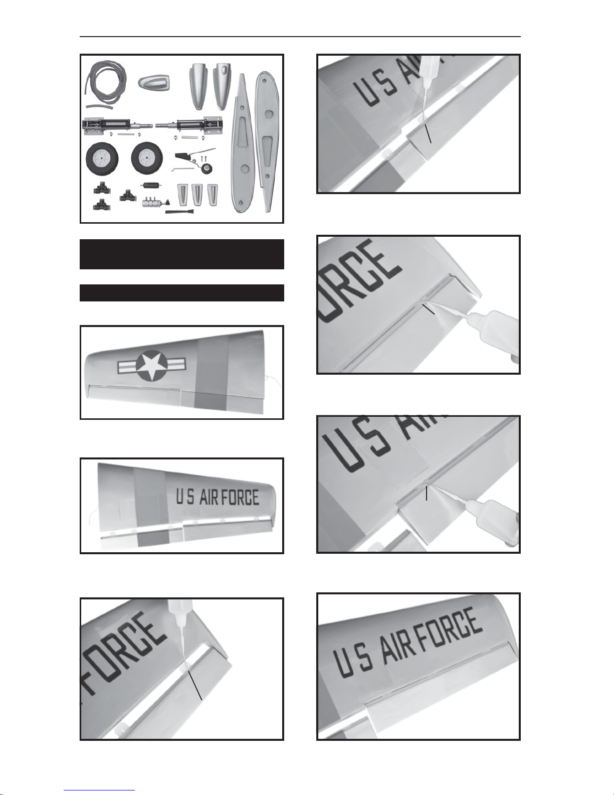
When self-tapping screws have to be
screwed into wood, apply a little white
glue to prevent them shaking loose: just
squirt white glue into the hole and fit the
screw.
+ This is not a toy
+ Be sure that no other flyers are using your
radio frequency.
+ Do not smoke near fuel
+ Store fuel in a cool, dry place, away from
children and pets.
+ Wear safety glasses.
+Theglowplug clipmustbesecurely attached
to the glow plug.
+ Do not flip the propeller with your fingers.
+ Keep loose clothing and wires away from
thepropeller.
+ Do not start the engine if people are near.
Donot standinlinewiththesideof thepropel-
ler.
+ Make engine adjustments from behind the
propeller only. Do not reach around the spin-
ningpropeller.
SAFETY PRECAUTION.
REPLACEMENT SMALL PARTS
B. Wing panel.
C. Fuselage.
A.Cowling.
D . Horizon stabilizer.
F. Aluminium wing dihedral brace.
E. Vertical stabilizer
C D
E
B
F A
B
B

AT.6-TEXAN - ITEM CODE: BH75.Instruction Manual
4
C/Aglue
C/Aglue
C/Aglue
INSTALLING THEAILERON SERVO
Aileron
C/Aglue
Top side
Aileron Flap
Flap Aileron
Bottom side
INSTALLING THE AILERON - FLAPSERVO
CONTROLHORN.

AT.6-TEXAN - ITEM CODE: BH75 INSTRUCTION MANUAL
5
C/Aglue
C/Aglue
C/Aglue
C/Aglue
1. Install the rubber grommets and brass
eyelets onto the aileron servo.
2. Usinga modelingknife, removethe cov-
ering servo tray.
INSTALLING THE AILERON SERVO .
Aileron
Flap Aileron
Bottom side
Servo tray.
Removecovering

AT.6-TEXAN - ITEM CODE: BH75.Instruction Manual
6
Nilon control clasp.
3 x 40mm
5. Instal servo tray with aileron servo into
the wing as same as picture below.
3.Drill 1,5mm pilotholes throughtheblock
of wood for each of the four mounting screws
provided with the servo. Install servo into ai-
leron servo tray as same as picture below.
4. Using the thread as a guide and using
masking tape, tape the servo lead to the end
of the thread: carefully pull the thread out.
When you have pulled the servo lead out, re-
move the masking tape and the servo lead
from the thread.
Markpoint
Thread
Electric wire
2x10mm.
Secure
INSTALLING THEAILERON CONTROL HORN.

AT.6-TEXAN - ITEM CODE: BH75 INSTRUCTION MANUAL
7
Aileron
Remove covering
Repeat the procedure for the other wing
half.
Installing the aileron linkages as pictures
below.
INSTALLING THE AILERON
LINKAGES.
M3 M3 lock nut
Installaileroncontrolhornassame
aspicturebelow.
Aileroncontrolhorn
Control horn
of the aileron

AT.6-TEXAN - ITEM CODE: BH75.Instruction Manual
8
2x10mm.
Thread
Electric
wire
Flap
Bottomside
INSTALLING THE FLAPSERVO . INSTALLING THE FLAP CONTROL HORN.
Nilon control clasp.
3 x 40mm
M3 lock nut
Flap
Removecovering

AT.6-TEXAN - ITEM CODE: BH75 INSTRUCTION MANUAL
9
Repeat the procedure for the other wing
half.
Installing the aileron linkages as pictures
below.
INSTALLING THE FLAP
LINKAGES.
Control horn
of the flap
INSTALLING AIR RETRACTABLE
LANDING GEAR.
AIR RETRACTS SYSTEM INSTALLATION.
Bottomside
Repeat the procedure for the other wing
half.
Aileron
Flap
Bottom of left wing.
Bottom of right wing.
3 x 15mm

AT.6-TEXAN - ITEM CODE: BH75.Instruction Manual
10
3 x 15mm
Markpoint
Secure
Secure
Secure

AT.6-TEXAN - ITEM CODE: BH75 INSTRUCTION MANUAL
11
Secure
Bottom side
3 way connector
valve one way
Valvecontrol
Top side

AT.6-TEXAN - ITEM CODE: BH75.Instruction Manual
12

AT.6-TEXAN - ITEM CODE: BH75 INSTRUCTION MANUAL
13
control valve
Secure
Secure
Cut
Airsupply Valveoneway
3way connector
Airtank
Vavle control
3way connector
3way connector
Right main
gearwing
Left main
gearwing

AT.6-TEXAN - ITEM CODE: BH75.Instruction Manual
14
Locatethealuminiumwingdihedralbrace.
Left side
Top right side
WINGATTACHMENT.
Bottom side
Right side
Top side

AT.6-TEXAN - ITEM CODE: BH75 INSTRUCTION MANUAL
15
Drill a hole 3mm
diameter
Secure
Drill a hole 3mm
diameter
Top left side
Secure
Bottom side
*** Test fit the aluminium tube dihedral brace
into each wing haft. The brace should slide in
easily. If not, use 220 grit sand around the
edges and ends of the brace until it fits prop-
erly.
3 x 40mm
Top side

AT.6-TEXAN - ITEM CODE: BH75.Instruction Manual
16
See pictures below:
4x30mm
4x30mm
INSTALLING THE ENGINE MOUNT.
Drill a hole
2mmdiameter
INSTALLING THE STOPPER ASSEMBLY
1) The stopper has been pre-assembled
at the factory.
2) Using a modeling knife, cut one length
ofsilicon fuelline(thelengthofsiliconfuel line
iscalculatedbyhowtheweightedclunkshould
restabout 8mmaway fromtherearofthetank
andmove freelyinside thetank). Connectone
FUEL TANK.
end of the line to the weighted clunk and the
otherend tothenylonpickuptubein thestop-
per.
3) Carefully bend the second nylon tube
up at a 45 degree angle (using a cigarette
lighter). This tube will be the vent tube to the
muffler.
4) Carefully bendthethirdnylontube down
ata 45degreeangle (usingacigarettelighter).
This tubewill bevent tubeto thefuelingvalve.
When the stopper assembly is installed in the
tank, the top of the vent tube should rest just
belowthe topsurfaceof thetank. Itshould not
touch the top of the tank.

AT.6-TEXAN - ITEM CODE: BH75 INSTRUCTION MANUAL
17
Do not secure the tank into place perma-
nently until after balancing the airplane. You
may need to remove the tank to mount the
battery in the fuel tank compartment
9) To secure the fuel tank in place, ap-
plya beadofsilicon sealerto theforward area
of the tank, where it exits the fuselage behind
theengine mountingbox andto therearofthe
tank at the forward bulkhead.
8) Feed three lines through the fuel tank
compartment and through the pre-drilled hole
in the firewall. Pull the lines out from behind
the engine, while guiding the fuel tank into
place. Push the fuel tank as far forward as
possible,the frontofthetankshould justabout
touch the back of the firewall.
7) Using a modeling knife, cut 3 lengths of
fuel line 150mm long. Connect 2 lines to the 2
vent tubes and 1 line to the fuel pickup tube in
the stopper.
Blow through one of the lines to ensure the
fuel lines have not become kinked inside the
fueltankcompartment.Airshouldflow through
easily.
5) Test fit the stopper assembly into the
tank. It may be necessary to remove some of
the flashing around the tank opening using
amodeling knife. Ifflashing is present, make
sure none of it falls into the tank.
6) When satisfied with the alignment of
thestopperassemblytightenthe3mmx20mm
machine screw until the rubber stopper ex-
pandsand sealsthetank opening.Do notover
tighten the assembly as this could cause the
tank to split.
Vent tube
Fuelfilltube
Fuel pick- up tube
Fueltank

AT.6-TEXAN - ITEM CODE: BH75.Instruction Manual
18
Locate the long piece of wire used for the
throttlepushrod. Oneendofthewire hasbeen
pre-bend in to a “Z” bend at the factory. This
“Z” bend should be inserted into the throttle
armofthe enginewhentheengine isfittedonto
theengine mount.Fittheengineto theengine
mount using the screws provided.
Right side
130mm.
Mark point
INSTALLING THE ENGINE.
Pushrod wire.
Drillahole 4mm
diameter

AT.6-TEXAN - ITEM CODE: BH75 INSTRUCTION MANUAL
19
4x 30mm
1) Slide the fiberglass cowl over the en-
gineand lineup thebackedgeofthe cowlwith
the marks you made on the fuselage.
3) Slide the cowl back over the engine
andsecure itin placeusing fourwood screws.
See picture below.
2) While keeping the back edge of the
cowl flush with the marks, align the front of
thecowlwiththecrankshaftoftheengine. The
front of the cowl should be positioned so the
crankshaft is in nearly the middle of the cowl
opening. Hold the cowl firmly in place using
pieces of masking tape.
4) Installthe mufflerandmufflerextension
onto the engine and make the cutout in the
cowl for muffler clearance. Connect the fuel
and pressure lines to the carburetor, muffler
andfuel fillervalve.
Secure
Right side
Left side
COWLING.
Trim and cut
Left side
Right side
3 x 12mm

AT.6-TEXAN - ITEM CODE: BH75.Instruction Manual
20
Left side
Right side
Machinescrew
INSTALLING THE THROTTLE PUSHROD
1. Install one adjustable metal connector
through the third hole out from the center of
one servo arm, enlarge the hole in the servo
arm using a 2mm drill bit to accommodate the
servo connector. Remove the excess mate-
rial from the arm.
After installing the adjustable metal con-
nector apply a small drop of thin C/A to
the bottom nut. This will prevent the con-
nector from loosening during flight.
Throttle servo
Connector.
Servo arm.
Secure
Cut
Table of contents
Other arf Toy manuals

arf
arf Tornado Owner's manual

arf
arf Katana User manual

arf
arf BO-209 MONSUN Owner's manual

arf
arf XPower P-51D MUSTANG User manual

arf
arf Fan Star User manual

arf
arf BO-209 MONSUN Owner's manual

arf
arf GILMORE Owner's manual

arf
arf PA-20 Pacer 10e User manual

arf
arf F4U Corsair .60 User manual

arf
arf P-51 MUSTANG User manual
Popular Toy manuals by other brands

Faller
Faller MOTORCYCLE SHOP manual

Fisher-Price
Fisher-Price POWER WHEELS ARCTIC CAT CGY61 owner's manual

STEAM Train
STEAM Train STEAMbot V1.0 user guide

Ripmax
Ripmax EF - 2000 TYPHOON Instruction manual book

Playskool
Playskool Busy Ball Popper 06104 instruction manual

Seagull Models
Seagull Models NIEUPORT 28 REPLICA Assembly manual