2
AVENSIS - Item code: BH137. Instruction Manual
This instruction manual is designed to help you build a great flying aeroplane. Please read this
manualthoroughlybeforestartingassemblyofyour AVENSIS.Usethepartslistingbelowtoidentify
all parts.
WARNING.
Please be aware that this aeroplane is not a toy and if assembled or used incorrectly it is
capable of causing injury to people or property. WHEN YOU FLY THIS AEROPLANE YOU
ASSUME ALL RISK & RESPONSIBILITY.
IfyouareinexperiencedwithbasicR/CflightwestronglyrecommendyoucontactyourR/Csupplier
and join your local R/C Model Flying Club. R/C Model Flying Clubs offer a variety of training
proceduresdesignedtohelp thenewpilotonhisway tosuccessfulR/Cflight.Theywill alsobeable
to advise on any insurance and safety regulations that may apply.
TOOLS & SUPPLIES NEEDED.
Thick cyanoacrylate glue.
30 minute epoxy.
5 minute epoxy.
Hand or electric drill.
Assorted drill bits.
Modellingknife.
Straight edge ruler.
2mm ball driver.
Phillips head screwdriver.
220 grit sandpaper.
90° square or builder’s triangle.
Wire cutters.
Masking tape & T-pins.
Thread-lock.
Paper towels.
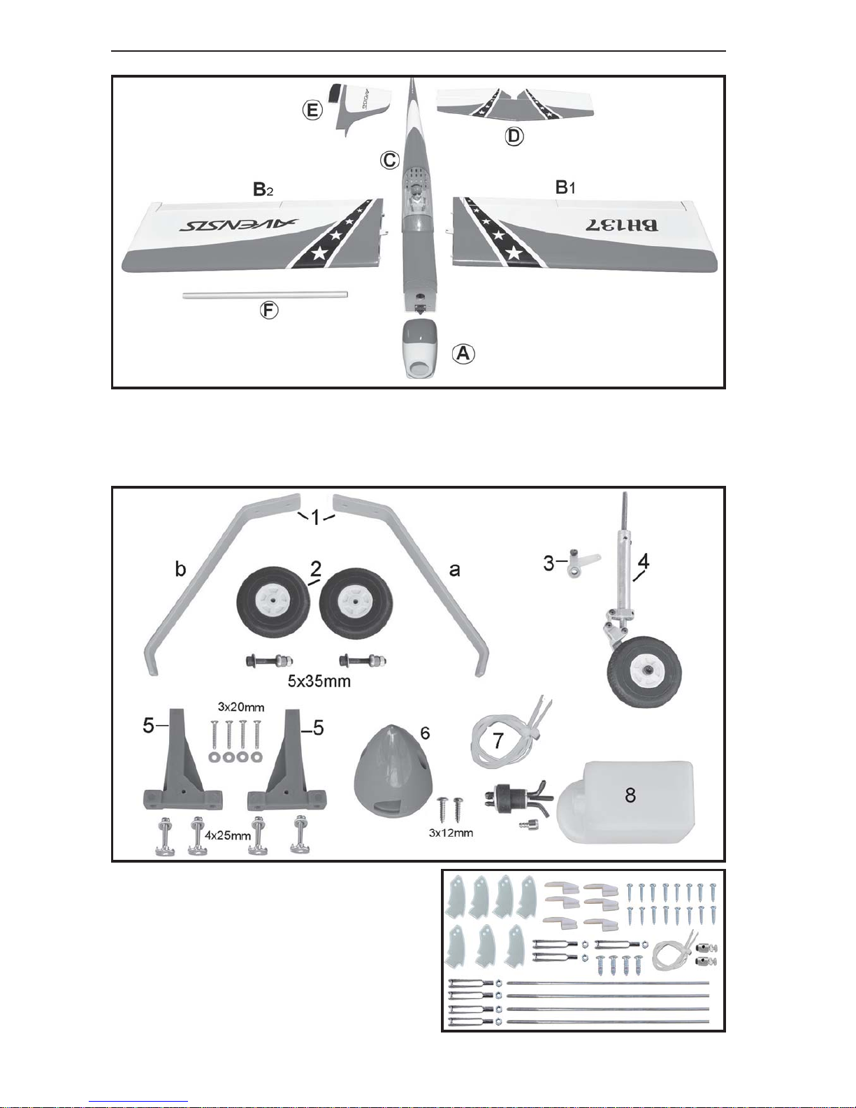
Some more parts.
HARDWAREPACK
COWLING.
Landinggear.....
Toavoidscratching yournewairplane, do not
unwrap the pieces until they are needed for
assembly. Cover your workbench with an old
towel or brown paper, both to protect the air-
craftandto protect the table. Keepacouple of
jars or bowls handy to hold the small parts af-
ter you open the bag.
Pleasetrialfitall theparts.Makesureyouhave
the correct parts and that they fit and are
alignedproperlybeforegluing!Thiswillassure
proper assembly.AVENSIS ARF is hand made
from natural materials, every plane is unique
andminoradjustments may have tobe made.
However, you should find the fit superior and
assembly simple.
The painted and plastic parts used in this kit
are fuel proof. However, they are not tolerant
of many harsh chemicals including the follow-
ing:paintthinner,C/Aglueaccelerator, C/Aglue
debonderandacetone. Donotletthesechemi-
cals come in contact with the colors on the
covering and the plastic parts.
PARTS LISTING.
FUSELAGE ASSEMBLY
(1) Fuselage.
WING ASSEMBLY
(1) Right wing half with pre-installed
aileron.
(1) Left wing half with pre-installed
aileron.
Tail section assembly
(1) Vertical stabilizer with pre-
installedrudder.
(1) Horizontal stabilizer with pre-
installedelevatorhalves.
SUGGESTION.
NOTE.