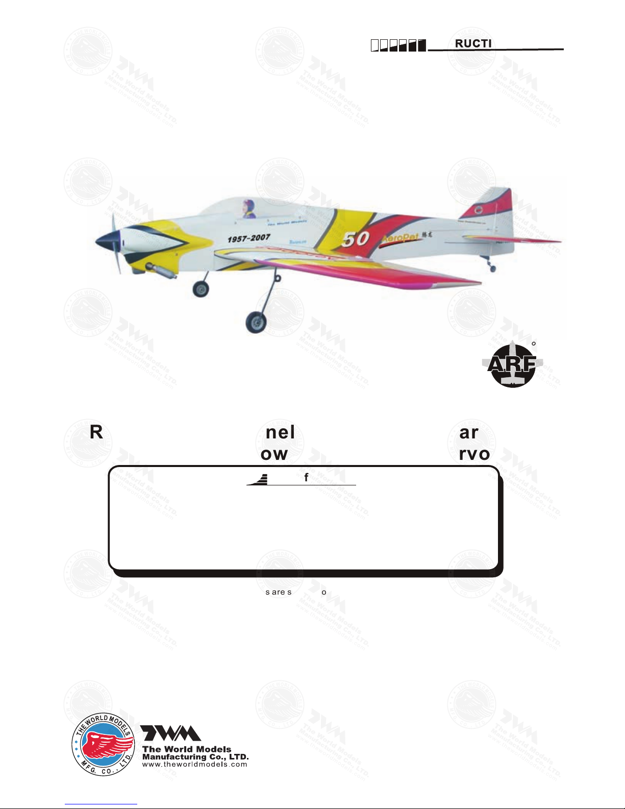
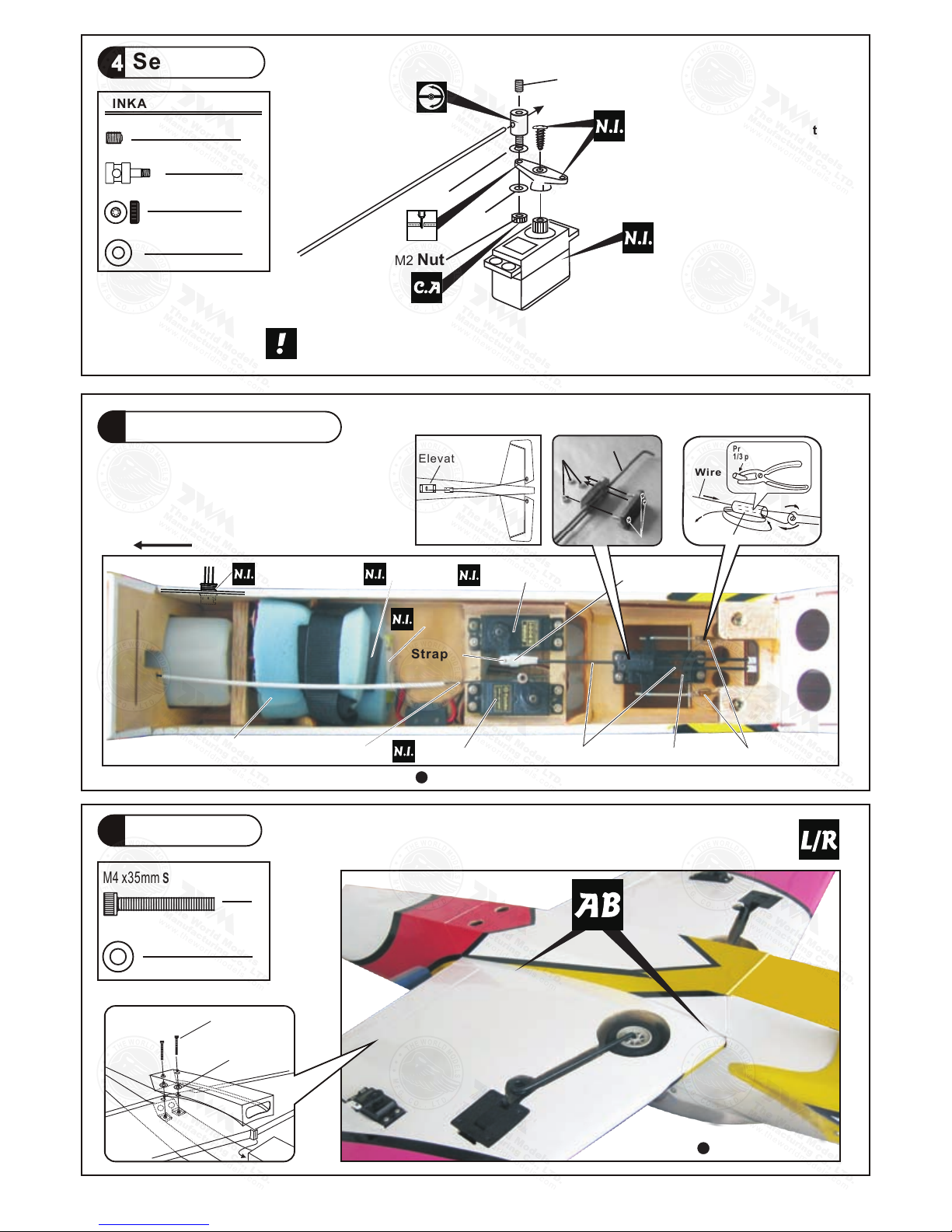
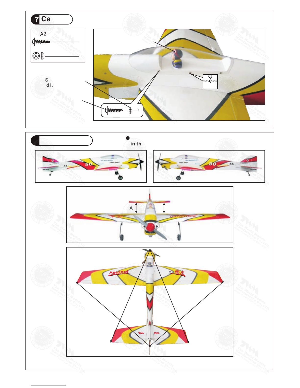
arf AeroPet 50 User manual

Warning ! This model is not a toy.
It is designed for maximum performance. Please seek advice if one is not familiar with this kind
of engine powered precision model. Operating this model without prior preparation may cause
injuries. Remember, safety is the most important thing. Always keep this instruction manual
at hand for quick reference.
* Specifications are subject to change without notice.*
INSTRUCTION MANUAL
Requires: 5 channel radio w/ 5 standard servos
and 1 low profile retract servo
-
.
Wing Span 55 in /1400 mm
Wing Area
Flying Weight
Fuselage Length
5 lbs / 2280 g
576.5 sq in / 37.2 sq dm
57.5 in /1460 mm
Specifications
AeroPet 50
AeroPet 50
0.52-0.70 cu.in.displacement 4-stroke
E
A
D
R
-
Y
T
-
T
S
O
O
-
F
M
L
L
Y
A
FACTORY PRE-FABRICATED
ALMOST-READY-TO-FLY (ARF) SERIES
MADE IN CHINA

INDEX
P. 3 - 10
BEFORE YOU BEGIN
PARTS LIST
ASSEMBLY
SAFETY PRECAUTIONS
P. 1
P. 2
P. 10
BEFORE YOU BEGIN
Check all parts. If you find any defective or missing parts contact your local dealer. Please DRY FIT
and check for defects for all parts that will require CA or Epoxy for final assembly. Any parts you find
to be defective after the gluing process may be difficult to remove for warranty replacement. The
manufacturer will replace any defective parts, but will not extend to the parts that are good before gluing
to defective parts during assembly. Warranty will not cover any parts modified by customer.
Read through the manual before you begin, so you will have an overall idea of what to do.
Symbols used throughout this instruction manual comprise of the following : -
1
2
3
P. 1
AeroPet 50
AeroPet 50
3mm
Do not overlook this symbol!
Cut off shaded portion.
Peel off shaded portion
covering film.
Pay close attention here!
Pierce the shaded portion
covering film.
Must be purchased separately!
Drill holes with the specified
diameter (here: 3mm).
Ensure smooth non-binding
movement while assembling.
Apply instant glue
(C.A.glue, super glue.)
Assemble left and right
sides the same way.
Apply epoxy glue.
Apply thread locker
Warning!

P. 2
19、
COVERING:-
TOUGHLON STL 313 PINK
TOUGHLON STL 204 CREAM
TOUGHLON STL 330 CRANGE YELLW
TOUGHLON STL 201 BLACK
TOUGHLON STL 311 CUB YELLW
TOUGHLON STL 100 WHITE
1、MAIN WING--1 pair
2
WING TUBE Ø16x400mm--1 pc.
3、SCREW PB2x20mm--4 pcs
PUSHROD Ø1.8x115 mm w/Threads(For Aileron)--2 pcs
HORN--2 sets
CLEVIS--2 pcs
STRAPER(PL4112102)--2 pcs
FUEL TUBE Ø6x5mm--4 pcs
5、STABILIZER & ELEVATOR--1 set
FUSELAGE--1 pc.
6、VERTICAL FIN & RUDDER--1 set
7、PUSHROD Ø1.8x720mm w/Threads(For Elevator)--2 pcs
SCREW PB2 x16mm--4 pcs
HORN--2 sets
CLEVIS--2 pcs
FUEL TUBE Ø6x5mm--2 pcs
8、SCREW PM2x20mm--2 pcs
CLEVIS--2 pcs
M2 NUT --2 pcs
HORN(w/o-Base For Rudder)--2 pcs
COPPER TUBE d2.5xD3.2x8mm(For Rudder)--2 pcs
WIRE Ø1x760mm--2 pcs
RIGGING COUPLER Ø1.8x27mm w/Threads(For Rudder)--2 pcs
FUEL TUBE Ø6x5mm--2 pcs
9、TAIL LANDING GEAR Ø2.1mm--1 set
SCREW PA3x12mm--2 pcs
COLLAR Ø2.1mm w/set screw--1 set
TAIL WHEEL Ø23mm--1 pc.
10、ENGINE MOUNT (Pl5111050)--1 set
SOCKET HEAD SCREW M4x25mm--4 pcs
WASHER d4.
5xD9mm--4 pcs
11、FUEL TANK 320CC--1 set
BALSA 8x8x77mm(For Fixing Fuel Tank)--1 pc.
12、SOCKET HEAD SCREW M3.5x30mm--4 pcs
WASHER d3.5xD8mm--8 pcs
M3.5 NUT--8 pcs
THROTTLE PUSHWIRE Ø1.2x410mm--1 pc.
PLASTIC TUBE d2xD3x250mm--1 pc.
13、
COWLING--1 pc.
TRANSPARENT DUMMY COWLING--1 pc .
SCREW PWA2.6x12mm--4 pcs
SILICON GROMMET d1.5xD6.5mm--4 pcs
SPINNER Ø52mm--1 set
14、
Ø2.1mm--3 sets
LINKAGE CONNECTOR
15、FUEL TUBE Ø6X5mm--1 pc.
STRAPER--1 pc.
SPONGE 10x80x200mm--2 pcs
PUSHROD CONNECTOR 4x9x20mm--1 set
COPPER TUBE d2.5xD3.2x8mm(For Rudder)--2 pcs
PUSHROD Ø1.8x100mm(For Elevator)--1 pc.
RIGGING Z BEND Ø1.8x27mm(For Rudder)--2 pcs
16、
BELLY PAN--1 pc.
SOCKET HEAD SCREW M4x35mm--2 pcs
WASHER d4.2xD14.5mm--2 pcs
17、
CANOPY--1 pc.
SCREW PWA2.3x8mm--6 pcs
SILICON GROMMET d1.5xD6.5mm--6 pcs
PILOT PC001050B--1 set
18、
DECALS :
A197DEC --1 set
Parts List

P. 3
1Main Wing
2Main Wing
Please apply glue to all surfaces of wing tube.
Wing Tube 16X400mm Ø
Aileron Servo Lead
App ly insta nt t ype CA glue to both si des of each
hin ge.
Completed

P. 4
3Aileron Servo
4Retractable Landing Gear Servo
5Stabilizer & Elevator
Wheels down Position
To
R-side
To
L-side
Wheels up position
3 x 3mm Set Screw
Linkage Connector
M2 Nut
2mm Washer
Adjuster
4
2
2
2
4
PB2 x20mm Screw
Completed
(Stabilizer)
(Main Wing)
BB'
BB'
Temporary install the main wing, adjust
leveling of the stabi lizer to make it as
parallel to the main wing as possible.
A A'
A=A'
*Also refer to step 18 Wing Setting
Bottom View
Ø1mm p ilo t h ole s for Worl d Mode ls tri -horn are pr e-drill ed.
Please look for pin-hole marks at under side of control surfaces.
Apply instant type CA glue to both sides of each hinge.
PB2X20mm
Pushrod
Clevis
Horn
Fuel Tube
D6X5mm
straper
Ø1.8x115mm
2mm
1mm
TWM PL8210010
CLEVIS WRENCH

P. 5
6Vertical Fin/Rudder
7Elevator Pushrod
8Rudder Pushwire
B=B
BB
285mm
78mm
PB2x16mm
Clevis
Fuel Tube
Ø6x5mm
2mm
Ø1.8
Elevator Pushrod
x720mm
2mm
Ø1mm pilot holes for World Models tri-horn are pre-drilled. Please
look for pin-hole marks at under side of control surfaces.
4
PB2 x16mm Screw
2
PM2 x20mm Screw
M2 Nut
2
Fuel Tube
Ø6 x 5mm
Copper Tube
d2.5xD3.2x8mm
PM2 x20mm
Ø1mm pilot holes for World Models tri-horn are pre-drilled. Please
look for pin-hole marks at side of control surfaces.
215mm
40mm
Apply instant type CA glue
to both sides of cach hinge.
Bottom View
Wire
Copper Tube
Press down the center
1/3 portion
TWM PL8210010
CLEVIS WRENCH

P. 6
9Tail Landing Gear
10 Engine Mount
11
Blind nuts are off-centered to keep
the spinner at the fuselage axis.
App ly t hrea d loc ker to scr e ws
M4 x25mm Socket Head Screw
4
d4.5x D9mm Washer
4
PA3x12mm
3mm Set Screw
PA3x12mm Screw
3mm Set Screw
2.1mm Collar
1
2
1
M4 x 25mm
Washer
d4 5x D9mm
.
Engine Mount
PL5111050
Fuel Tank
Bottom View
UP
Fuel Tank
320cc
Install Balsa 8x8x77mm
(For Fuel Tank Position Fixing )
320cc

P. 7
12 Engine
4
8
M3.5x30mm Socket Head Screw
d3.5xD8mm Washer
M3.5 Nut
8
Install Engine position
Spinner
Ø52mm
13 Cowling
PWA2.6 x 12 mm Screw
d1.5 x D6.5 mm Silicon Grommet
4
4First insert the grommet to the cowling then apply screw.
PWA2.6 x 12 mm
Silicon Grommet
d1.5xD6.5mm
Spinner 52mm
Ø
M3.5x30mm
Washer
d3.5xD8mm
M3.5 Nut
Throttle Pushwire
Ø1.2x410mm
Plastic tube
d2xD3x250mm
115mm
4.5 in
1.5mm
Fuel Filler
PL8110030

16 Main Wing
P. 8
14 Servo Set
3 x 3mm Set Screw
Linkage Connector
M2 Nut
2mm Washer
3
3
3
6
LINKAGE CONNECTOR
15 Radio Equipment
Throttle Pushrod
Fuel Tube
Ø6x5nm
Elevator Servo
Straper
M4 x35mm
Washer
d4.2xD14.5mm
2
2
M4 x35mm Socket Head Screw
D4.2xD14.5mm Washer
Sponge
10x80x200mm
Throttle Servo
Front
Copper Tube
Elevator Pushrod Rudder Servo
Bottom View
Bottom View
Included with the radio Set.
Please refer to attached sheet for linkage connector installation.
Throttle Pushwire
3x3mm Set Screw
Throttle Servo.
2mm
2mm
Washer
M2 Nut
2mm
Washer
Receiver
Battery
KM2x8mm
M2 Nut
Elevator Push rod
Ø1.8x100mm
Wire
Copper Tube
Press down the center
1/3 portion
Elevator Servo
Charge Receptacles
KP0041300

P. 9
17 Canopy
18 Wing Setting
C'
B'
C
B
A A'
A=A' B=B' C=C'
d1.5 x D6.5 mm Silicon Grommet
6
6
PWA2.3 x8mm Screw
PWA2.3 x 8 mm
Silicon Grommet
d1.5xD6.5mm
Pilot
Adjust the wing and fuselage configuration as shown
in the diagrams.
1mm

P. 1 0
Important Safety Precautions
#First time flyer should never fly by himself / herself. Assistance from experienced flyer is
absolutely necessary.
#Pre-flight adjustment must be done before flying, it is very dangerous to fly a badly
pre-adjusted aircraft.
# is specially designed to be powered by 4c 0.52-0.70 engine, using a
more powerful engine does not mean better performance. In fact, over powered engine
may cause severe damage and injuries.
#Make sure the air field is spacious, never fly the plane too close to people and never get
too close to a running propeller.
#If you find wrinkles on the covering as a result of weather changes, you can use hot iron
to remove the wrinkles. Please begin with lower temperature setting and gradually raise
the temperature until the wrinkles are gone. Too hot an iron may damage the covering.
#Check and re-tighten up all factory assembled screws, use thread locker if applicable.
19 Control Throws Adjust the control throws as shown in
the diagram. These throws are good for
general flying. You can adjust according
to your personal preference.
Aileron
12mm
Elevator
15mm
Rudder
40mm
20 C.G.The ideal C.G. position is 135mm (5.31 in) behind the leading edge measured at where
the wing meets the fuselage. In order to obtain the C.G. specified, add weight to the
fuselage or move the battery position. Check the C.G. before flying.
A197PO21520908
40mm
15mm
12mm
Measure C.G. with the wheels in retracted position
C.G.
AeroPet 50
AeroPet 50
135mm
5.31 in
Warning!

LINKAGE CONNECTOR
HW7111050 & HW7111060
After fastening the round nut, make sure that
the linkage connector can rotate freely.
Drill 2mm hole at servo horn.
Insert linkage connector
into servo horn.
Make sure shoulder of
screw is cleared from
servo horn.
Add washer to reduce
play if necessary.
Shoulder
Tighten up the round nut
against the shoulder. Apply
CA or permanent thread
locker.

Product Registration Form (US Customers)
We would like to share with you any relevant information regarding your model, including
product news and free upgrade parts when applicable. Please fill in the following and send to
AirBorne Models, 4749-K, Bennett Drive, Livermore, CA 94551 USA.
1. Name:
2. Address:
3. Phone #: E-mail:
4. Model:
Wing QC# Fuselage QC#
(QC numbers are stamped on wing and fuselage)
5. Date of Purchase:
6. Store Name:
Please call AirBorne Models at 925 371 0922 for any assistance in filling this form.
Thank you very much for purchasing our product.

Code N o.Size Package
Code No.Size Package
Code No SV4031
KP0041300
Special tool for clevis installation.
Suitable for standard and small
(EP)clevis.
Large Clevis
Small Clevis
180mm Extension

A197PO21520908
The World Models
Manufacturing Co., LTD.
www.thew orldm odels .com
Warbirds
Scale
Sports
Trainer
DuctedFan Pattern
Funfly
Electric
Glider
Boat
Accessories
Covering
(Lightex / Toughlon)
Table of contents
Other arf Toy manuals

arf
arf SBACH300 20CC V2 User manual

arf
arf LITTLE TONI EP User manual

arf
arf YAK 55M User manual

arf
arf P-51 MUSTANG User manual

arf
arf PITTS 30CC V2 User manual

arf
arf Tornado Owner's manual

arf
arf BH67 User manual

arf
arf MINIMOA GLIDER User manual

arf
arf Composite QQ Yak 54 2.6 m User manual

arf
arf MX2 50CC V2 User manual
Popular Toy manuals by other brands

taiyo
taiyo Octo Spinner 360 owner's manual

CIC
CIC Solar Wild Boar Assembly and instruction manual

Mattel
Mattel Mega Bloks Hot Wheels Cloud Cutter quick start guide

Kadee
Kadee The Coupler People Cushion 50 Foot PS-1 Box... Assembly instructions

OESD
OESD Magic Box instruction manual

Playskool
Playskool Rockin' Radio 6095 instruction manual