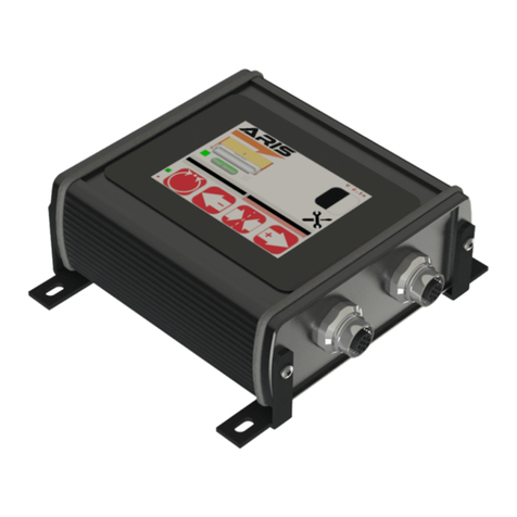
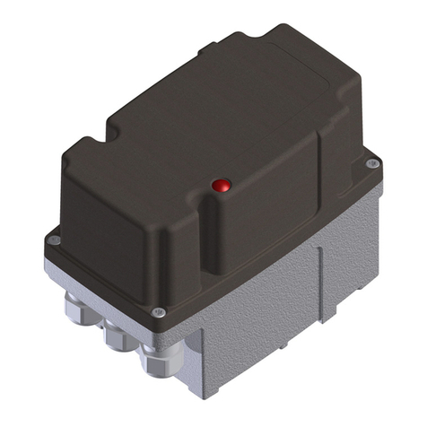
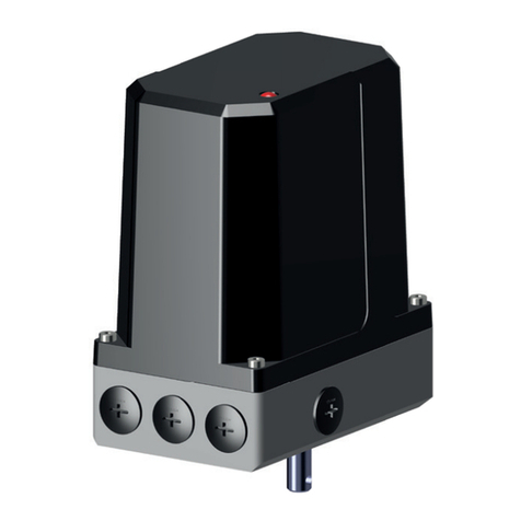
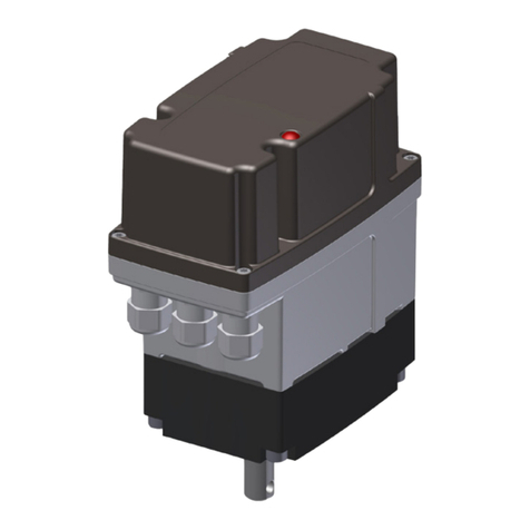
ARIS Nano+ User manual

Original declaration of
incorporation with manual for
ARIS Actuator Nano+
NA+2308EN01
Stellantriebe
incl. manual for
ARIS Microprocessor-Controller PMR-Nano

Inhaltsverzeichnis
Identication..............................................................................................................................................................................3
Nameplate .................................................................................................................................................................................3
Guidelines and standards............................................................................................................................................................4
Safety information......................................................................................................................................................................4
Warnings.................................................................................................................................................................................... 4
General safety advices................................................................................................................................................................ 4
Technical specication.................................................................................................................................................................5
Function and application areas (Intended use)............................................................................................................................. 5
Safe and accurate use.................................................................................................................................................................5
Performance data.......................................................................................................................................................................8
Expected lifespan and intended disposal......................................................................................................................................8
Actuator setup for utilization.......................................................................................................................................................8
Transport and (temporary) storage..............................................................................................................................................8
Packaging..................................................................................................................................................................................9
Safe disposal of packaging.......................................................................................................................................................... 9
Installation and mounting...........................................................................................................................................................9
Initial operation........................................................................................................................................................................10
Electrical connection..................................................................................................................................................................10
Wiring diagram ........................................................................................................................................................................11
Operation of the actuators ........................................................................................................................................................11
Set up rotation direction............................................................................................................................................................ 11
Set up limit switches (Self-adjusting switch cam).........................................................................................................................12
Optional modules and extra features......................................................................................................................................... 12
Potentiometer...........................................................................................................................................................................12
Potentiometer with approval acc. to DIN EN 12067-2 (TÜV-Poti).................................................................................................12
Additional limit switches (Self-adjusting switch cam)...................................................................................................................14
2-wire-current output 4-20 mA..................................................................................................................................................14
Mechanical position indicator.....................................................................................................................................................15
Service switch (230 V AC only)..................................................................................................................................................15
Heating resistant (230 V AC only)..............................................................................................................................................15
Single wire control (230 V AC only)...........................................................................................................................................16
Parallel relay (230 V AC only)................................................................................................................................................... 16
Power supply 24 V DC (Special edition)......................................................................................................................................17
Required customer information.................................................................................................................................................17
Extraordinary situations............................................................................................................................................................17
Troubleshooting and repair .......................................................................................................................................................18
Maintenance.............................................................................................................................................................................18
Service..................................................................................................................................................................................... 18
Accessories...............................................................................................................................................................................18
Spare parts...............................................................................................................................................................................18
ARIS Stellantriebe GmbH
53842 Troisdorf/Germany Fax: +49 2241 25186-99 www.stellantriebe.de
3Nano+
1. Identication
This manual is valid for:
Description: Electric actuator
Type: Nano+ S / Nano+ M
Serial no.: 1539-xxxxx-01001 ff.
1.1 Nameplate
Serial number
Actuator type
Voltage/Frequency/Power consumption
Actuating time/Torque
Ambient temperature/Protection class
Additional built-in parts
ARIS Stellantriebe GmbH
Rotter Viehtrift 9
D-53842 Troisdorf
www.stellantriebe.de
SNr: 1539-XXXXX-01001
Typ: Nano+ S
230V, 50(60)Hz 12VA
60(50)s/90° 40 Nm
UT -15°C/+60°C IP65
1ZW
Made in
Germany
Stellantriebe

4Nano+
1.2 Guidelines and standards
ARIS actuators are partly completed machinery according to directive 2006/42/EC. This is certied by a declaration of incorporati-
on (see page 14).
Further applicable EC directives: EMC Directive 2004/108/EC
Applied harmonized standards: LVD (electrical safety) DIN EN 61010-1:2011-07
MachDir DIN EN 12100:2011-03
EMC Directive 2004/108/EC DIN EN 61000-3-2
DIN EN 61000-3-3
DIN EN 61000-6-2
DIN EN 61000-6-3
DIN EN 55011:2001-04
DIN EN 61000-6-4:2011-09
Protection classes by housing (IP-Codes): Protection class test DIN EN 60529:1991
EMC consideration of the complete plant and system pertubations and their combating
have to be carried out by the plant builder or operator. The wiring of the actuator should
comply with DIN EN 60204-1.
2. Safety information
2.1 Warnings
Symbols: Installation and initial operation only by certied experts according to the manual.
Observe the signicance of the following symbol and note explanations. They are subdevided in security levels and classied
according to ISO 3864-2.
DANGER indicates a hazard with a high risk degree, which, if not avoided, causes death or
heavy injuries.
WARNING indicates a hazard with a medium risk degree, which, if not avoided, can cause
death or heavy injuries.
CAUTION indicates a hazard with a low risk degree, which, if not avoided, can cause slight
or moderate injuries.
Indicates general advices, useful hints and work recommendations, which don´t have
inuence on the safety and health of the staff.
2.2 General safety advices
The actuator components are conform to the state of the art and apply as generally safe at the time they are shipped.
This manual serves as basis to install and operate ARIS actuators safety conform. All persons working with or on ARIS actuators
must observe this manual and especially its safety advices.
DANGER
ADVICE
!
CAUTION
WARNING
HINWEIS
!

5Nano+
• This manual has to be kept at the operating place at any time.
• Read the manual carefully prior to installation and initial operation.
Certain parts of active electric appliances are obligatory under voltage.
• Working on electric appliances or equipment is only allowed for electrically qualied persons or other instructed persons
under guidance and custody of an electrically qualied person according to the electro-technical regulations.
• Observe all safety and accident prevention regulations while installing, operating and testing any electrical appliances or
machinery.
• Prior to all installation or regular work on the actuator make sure to switch off all connected machinery/appliances.
3. Technical specication
3.1 Function and application areas (Intended use)
ARIS actuators are exclusively designed for industrial use. ARIS actuators are utilized for operating regulating and shut-off applian-
ces (valves, ball valves, slide valves, dosing pumps, etc.).
ARIS actuators may not be used for:
• Potentially explosive atmospheres
• Temperatures below -15 °C or over 60 °C (optional +80 °C)
• Underground environments
• Near open res
• Under water
3.2 Safe and accurate use
ARIS actuators are factory checked prior to delivery. The nal functional testing must be performed within the total system by
qualied technical personnel.
The ARIS company assumes no liability for possible manufacturing errors and resulting damages or subsequent damages after the
actuator has been tested, installed and declared functional correct. The ARIS company especially assumes no liability for possible
manufacturing errors and resulting damages or subsequent damages when the actuator was operated inappropriate, has not
sufciently been tested within the total system, or has not been put out of operation after a failure has determined during testing.
Installation and initial operation only by qualied experts.
• Valves, levers and connecting rods are moving during actuator operation;
• Check for proper function of all emergency equipment on your machinery;
• Check for proper function of the actuator and operated valves after completion of all installation work;
• Never work with or operate a faulty actuator.
ADVICE
!
WARNING
CAUTION

6Nano+
3.3 Dimensions
Round shaft
with cross hole
(Standard)
Round shaft
with feather key
(Option)
D-shaft
(Option)
ISO shaft
inner 4-square
(Option)
Cable glands optional
(Standard=blind plugs)
H=73 mm/102 mm,
depending on options
Nano+ S
11
Ø20 4kt SW11
ISO shaft
Internal four square
(Option)
40
Round shaft
with cross hole
(Standard)
40
16
4
3
Round shaft
with feather key
(Option)
30
25
Ø10
D shaft
(Option)
Ø12
8
Ø12
6
Ø 5
T=2,5
65
6063 10
50
M6x9
2525
F05 Ø50
F03 Ø36
M6x9
M5x9
42
86
153
optional

7Nano+
Round shaft
with cross hole
(Standard)
ISO shaft
inner 4-square
(Option)
Round shaft
with feather key
(Option)
Nano+ M
14
4kt SW14
ISO shaft
Internal four square
(Option)
40
Round shaft
with cross hole
(Standard)
40
L
P
3
Round shaft
with feather key
(Option)
D
D
6
B
F05 Ø50
M6x11
50
2525
153
86 6340 10 60
M6x11
65
82
optional
T
Type D B L P T
30-40 Nm 12 5 16 4 2.5
50-60 Nm 14 6 22 5 3

8Nano+
3.4 Performance data
• Protection class: IP65 (optional IP 66, IP 67)
• Motor: 230V ±10%, 50/60Hz ±5%, 100% ED (Standard)
» Special voltage/-frequency see nameplate (Option)
» Insulation class E acc. DIN EN 60034-1
• Motor: 24 V DC (Option) ±20%, ED S3 50%
» Insulation class E acc. DIN EN 60034-1
• Connection: 3 cable glands M16x1.5 (Customer provided)
• Path cut-off: Changeover switch (Opener/Closer)
» Switching capacity max. 10(3)A, 250V AC
• Ambient temperature
» -15 °C up to +60 °C (optional -30 °C...+80 °C)
• Installation position: Arbitrary
• Potentiometer (Option)
» Recommended wiper current: 0,2 μA
» Capacity at +70 °C: 0,5 W
• Travel: 10°…330°, Multi Turn (Option)
3.5 Expected lifespan and intended disposal
ARIS actuators have an expected lifespan of several years, depending on their utilization and application. No longer usable actu-
ators must not be dismantled as a whole, but seperately recycled in parts divided by their materials. Non-recyclable components
must be disposed according to national disposal regulations.
4. Actuator setup for utilization
4.1 Transport and (temporary) storage
Use the factory packaging for transport to the installation point.
Replace a damaged original packaging by a new solid packaging.
Suspended load
Improper use of transportation (ground conveyer, overhead crane, tools, lifting means etc.) can cause crushes and other injuries.
Required behaviour:
• Use transportation properly;
• DO NOT step or stand under suspended loads;
• Actuators with attached valves: Attach lifting gear only on the valve and NEVER on the actuator;
• Do not use ARIS actuators as a climbing or support aid;
Damage by wrong storage
• Store in well-ventilated rooms;
• Protection against possible ground humidity (shelf storage).
WARNING
ADVICE
!

9Nano+
4.2 Packaging
ARIS actuators are protected by special cardboard packaging at delivery.
4.3 Safe disposal of packaging
Additionally necessary packaging is made by easily separable packaging materials and can be recycled individually:
• Wood
• Cardboard
• Paper
• Plastics
4.4 Installation and mounting
• Inspect the actuator for damages prior to installation;
• the screw-in depth of connecting thread holes must not exceed 9 mm;
• check leak tightness of cable glands and blank plugs prior to initial operation;
• tighten the cover screws evenly (max. 1.2 Nm);
• do not operate before limit switches have been adjusted;
• protect the actuator against climatic inuences (e.g. by a protective cover);
• do not expose the actuator to hard shocks (e.g. by dropping);
• do not attach ropes, hooks or the like to the actuator;
• permanent overload and blocking leads to actuator damages;
• spark suppressor capacitor can effect the rotation stability of the actuators and may cause damages;
• use only ARIS original spare parts.
Consider prior to attachment of couplings:
• Do not turn actuator shafts by force;
• actuator and valve shafts must run centrical (possible adjustment by exible coupling);
• the attachment to the valve is made by actuator-attached brackets.
Installation position: The actuators can be installed position independendly.
Protection classes IP65, optional IP66/IP67
For all actuators observe the following advices:
The initial operation of the actuator is only permitted with orderly closed cover and closed cable entries. Use only cable glands
which are appropriate for the respective protection class.
• Cable entries
Ensure that all cable entries are closed properly during storage, installation and initial operation.
Use only cables which are suitable for the diameter of the cable entries.
ADVICE
!

10 Nano+
• Cover assembly
During the cover assembly make sure that the cover ts correctly.
The cover must not show any damages on the joint surface.
Tighten cover screws evenly (max. 1.2 Nm).
• Housing/Cover
No additional bores are allowed in the housing and the cover.
4.5 Initial operation
4.5.1 Electrical connection
Hazardous voltage: Possible stroke!
• The initial operation must be carried out only by experts!
• De-energize the actuator before opening.
• Observe the appropriate regulations during electrical installation and initial
operation.
Connect the actuator as follows:
• Connect the ground wire of the electric supply to the appropriate protective earth terminal.
• Connect the neutral N to terminal 1.
• Follow the steps under „Set up rotation direction“ (S. 11) during connection of the actuator.
• Always refer to the wiring diagram located inside the actuator.
Check before you close the circuit for the rst time:
• Is the actuator undamaged on the outside?
• Is the mechanical connection correct?
• Has the electrical connection been made regularly?
• Check if current type, voltage and frequency match with the motor data (see nameplate on cover and inside the actuator).
• Insert suitable cable glands for the connection line.
• Observe the wiring diagram inside the cover.
• Use separate (shielded) wires for low voltages (e.g. potentiometer).
• Set up limit switches prior to initial operation (see page 12).
All elements, such as switches, potentiomer etc., are factory-wired.
Never change the internal wiring.
ADVICE
!
CAUTION
WARNING

11Nano+
8
67
S1
11
910 5455
+–
Strom-
ausgang
S2
Standard Optionen
14
1213
S3
17
1516
S4
4.5.2 Wiring diagram
SL Limit switch, CCW
SR Limit switch, CW
S1 Auxiliary switch 1
S2 Auxiliary switch 2
R1 Potentiometer 1
All auxiliary switches must be operated within the same voltage range. Do not mix line
voltage with low voltage.
5. Operation of the actuators
5.1 Set up rotation direction
Due to the internal wiring, the rotation direction (viewing direction is through the actuator towards the shaft) and the limit switches
assign as follows:
1. With line voltage on terminal 1 and 2, the actuator shaft rotates counter-clockwise. Limitation of this rotation direction
with upper switch SL. When the switch is activated, line voltage is on terminal 4.
2. With line voltage on terminal 1 and 3, the actuator shaft rotates clockwise. Limitation of this rotation direction with lower
switch SR. When the switch is activated, line voltage is on terminal 5.
3. If the actuator runs counterrotating to the commands, change the external connection of terminal 2 and 3 .
Depending on the model, limit switches may be arranged different than drawn in the wiring
diagram (see wiring diagram inside the actuator).
ADVICE
!
ADVICE
!
Current
output
Options
M
+L +R 5T+ 4
SL SR
–
Steuerelektronik
+24V -24V
SL SR
24V DC
Option 24 V DC
see chapter 5.3.10
+L Limit switch, CCW
+R Limit switch, CW
T+ +24V DC
(Manual override see chapt. 5.3.9.1)
– -24V DC
4 Feedback left end position
5 Feedback right end position

12 Nano+
5.2 Set up limit switches (Self-adjusting switch cam)
The switch cams are turnable by hand and can be fastened by a thread pin, e.g. if strong
vibrations apply.
1. Apply voltage (see page 10): Actuator rotates in given direction.
2. Switch off voltage when the desired end position has reached (no blocking of gear).
3. Turn switch cam L in rotating direction of the cam shaft E until limit path switch SL clicks. Now
the thread pin F can be xed with a hex wrench (enclosed).
4. Set up switch cam R for contrary rotating direction as described under step 1–3.
5. Check setup by moving the actuator again electrically and adjust if necessary.
5.3 Optional modules and extra features
5.3.1 Potentiometer
Electrical connection
Connect terminals 18, 19 and 20 according to the desired requirements (voltage ≤ 50V); (see page 10). Use only separate
(shielded) wires.
Adjustment
Set up limit switch before adjusting the potentiometer P. Approach both end positions electrically
(see chapter 5.2).
Observe travel and potentiometer solution.
Do not overrun the ordered travel to avoid damage to the friction clutch R by permanent
override. Potentiometer P adjusts roughly automatically.
The travel of the valve is transferred to the rotating angle of the potentiometer by the friction
clutch R. Approach both end positions again electrically (see page 15) and adjust potentiometer
P with the friction clutch R.
5.3.2 Potentiometer with approval acc. to DIN EN 12067-2 (TÜV-Poti)
Fail-safe potentiometer return for regulation of fuel, air and exhaust streams in combination with electronic compound control
systems.
At delivery the wiper is in the electrical center.
ADVICE
!
1
2
R
E
S1
S2
SR
LSL
P
R
F
ADVICE
!

13Nano+
Overview TÜV-Poti
Electrical connection
Connect terminals 18, 19 and 20 according to the desired needs (voltage ≤ 50V); (see page 11). Use only separate, shielded wires.
Adjustment
Set the limit switch prior to adjustment of the potentiometers SP28. Electrically drive towards both end positions (see chapter 5.2).
Match both travel and potentiometer resolution.
Within the long holes, the poti can be rotated up to 20° per hole (Fig. 1). If a rotation of more than 20° is necessary, the poti
fastening screws are moved to the next hole. Then poti kann be moved in 20° steps up to 360° (Fig. 2). Fasten the screws with a
torque of 1.8 Nm.
It is mandatory that the factory-set TufLok screws must be used after loosening.
Recommendation: Secure the poti fastening screws with thread-lock uid.
ADVICE
!
Poti Novotechnik SP28
Micro switches
Switch cams
Fig. 1
Poti adjustment up to 20°: Adjustment within
the long holes. No move of screws necessary.
Fig. 2
Poti adjustment 20° to 360°: Screws must be moved.

All potis must generally run under a potential divider circuit.
5.3.3 Additional limit switches (Self-adjusting switch cam)
The switch cams can be rotateted by hand an can additionally be xed with a thread pin,
e.g. at strong vibrations.
1. Approach desired position. Switching position must be approached from the desired rotating
direction.
2. Turn switch cams „1“ to „4“ in rotating direction of the cam shaft E until limit switch „S1“ to „S4“
clicks. Now the thread pin F can be xed with a hex wrench (enclosed).
3. Check setup by moving the actuator again electrically and adjust if necessary.
5.3.4 2-wire-current output 4-20 mA
Electrical connection
Connect terminal 54 and 55 according to the wiring diagram (see page 10). Use separate (shielded) wire with minimum diameter
of 0.5 mm² and a max. length of 1000 m.
Setup
Operate the current output via buttons „4“ and „20“. Assigning arbitrary positions for 4 mA and 20 mA is possible at any time. The
lower and upper current limit (4/20 mA) is programmed steady.
a) Assignment of end position 4 mA:
• Approach end position;
• press button „4“ more than 2 sec.;
• release button „4“;
• the end position is programmed and active at once.
b) Assignment of end position 20 mA:
• Approach end position;
• press button „20“ more than 2 sec.;
• release button „20“;
• the end position is programmed and active at once.
18
19
20 U+
U–
UM
ADVICE
!
ADVICE
!
F
4
3
1
E
S4
S3
S1
2S2
RSR
LSL

Nano-SSI 1.0
EXT
INT
SW1SW2
R
L
ARIS
5.3.5 Mechanical position indicator
The mechanical position indicator serves as a reference for the shaft position on the sight-glass and it is
adjustable.
Adjustment: Adjust the mechanical position indicator by turning the angle pointer (marked with an arrow)
and the enclosed arrow labels.
Ratio position indicator to valve position on Nano M:
Type Pos.ind. at 90° Type Pos.ind. at 90° Type Pos.ind. at 90° Type Pos.ind. at 90°
M 30-06
193.5°
M 40-09 288° M 50-20
288°
M 60-20
288°
M 30-12 M 40-12 193.5° M 50-50 M 60-50
M 30-30 M 40-30 193.5° M 50-90 M 60-90
M 30-60 M 40-60 193.5° M 50-180 M 60-180
M 30-120 M 40-120 193.5°
The ratio at Nano S is always 1 : 1
5.3.6 Service switch (230 V AC only)
Adjusting and service work can be done by using the service switch.
Operation:
Set the switch „SW2“ to „INT“ „Manual operation“. The actuator can now be moved
via the switch „SW1“ left (position „L“) or right (position „R“).
For operation by an external controller, set the switch „SW2“ to „EXT“. Switch „SW1“
is without function now.
5.3.7 Heating resistant (230 V AC only)
Heating element for use of actuators in cold-humid environments. To avoid condensation water inside the actuator at uctuating
temperatures.
The heater resistant is wired at factory. Never change the internal wiring. Observe the
wiring diagram insode the actuator cover.
27 28
R4
N L1
ADVICE
!

5.3.8 Single wire control (230 V AC only)
For use as open/close regulation by external controller or switching appliances with
normally open or break contact. The rotation direction reverse is made by a built-in
switching relay.
The add-on board with the single wire control is wired at factory. Never change the internal
wiring. Observe the wiring diagram insode the actuator cover.
5.3.9 Parallel relay (230 V AC only)
The integrated relay makes it possible to run several actuators in parallel mode over
one switching contact.
The add-on board with the parallel relay is wired at factory. Never change the internal
wiring. Observe the wiring diagram insode the actuator cover.
M
1 2 3 4 5 A B
N
M
1 2 3 4 5 A B
N
ADVICE
!
ADVICE
!

5.3.10 Power supply 24 V DC (Special edition)
5.3.10.1 Service switch
Use the service switch to perform adjustment and service works on the actuator. For this, terminal T+ must hold a direct current of
24 V DC.
Operation:
Set the sliding switch to „MANU“ (manual operation). The actuator can now be moved left with the button „L SW1“ (position „L“) or
right with the button „R SW2“ (position „R“). For operation via an external controller set the sliding switch to „AUTO“. The buttons
„L SW1“ and „R SW2“ are without function now.
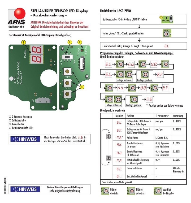
Die Stellzeit eines Antriebes mit Gleichstrommotor verändert sich lastabhängig. Die angege-
bene Stellzeit bezieht sich auf eine Belastung des Antriebes mit dem ebenfalls angegebenen
Drehmoment (s. Typenschild)
6. Required customer information
6.1 Extraordinary situations
Run frequent testings during operation. Observe especially:
• Intended use of the actuator (chapter 3.1);
• unusual noise, heavy vibration or high temperatures;
• check screws for tight seat;
• check cable entries, cable glands and blank plugs for tight seat and possible leakness;
• condition of electric wires.
If failure appear, set the actuator out of order and correct the error.
If you can not correct the error, contact an ARIS service person.
More information under: www.stellantriebe.de
L SW1 SW2 R
AUTO
MANU
ADVICE
!
ADVICE
!

6.2 Troubleshooting and repair
Hazardous voltage: Possible stroke!
• Troubleshooting and repair only by experts!
• Cut off voltage before opening the actuator.
Moving parts at built-on valves: Possible bruise!
• Troubleshooting and repair only by experts!
We recommend a repair at the ARIS factory.
More information under: www.stellantriebe.de
7. Maintenance
7.1 Service
ARIS actuators of type Nano have a lifetime lubrication and are generally maintenance-free.
7.2 Accessories
No special tools are required for installation. The required hex wrench is enclosed with the delivery.
7.3 Spare parts
Please always state the serial number of the actuator.
ADVICE
!
CAUTION
WARNING
ADVICE
!
ARIS Stellantriebe GmbH Tel.: +49 2241 25186-0
Rotter Viehtrift 9 Fax: +49 2241 25186-99
www.stellantriebe.de Stellantriebe
Subject to technical changes.

Manual for
ARIS Microprocessor-
Controller PMR-Nano
115 V AC / 230 V AC only
PMRN2211EN01
Stellantriebe

Table of content
Intended use ............................................................................................................................................................................21
Electrical connection..................................................................................................................................................................21
Wiring diagram ........................................................................................................................................................................22
Circuit board............................................................................................................................................................................. 23
General information .................................................................................................................................................................23
DIP switches .............................................................................................................................................................................24
Programming........................................................................................................................................................................... 24
Menu .......................................................................................................................................................................................25
End positions............................................................................................................................................................................26
Cams........................................................................................................................................................................................ 26
0% assignment.........................................................................................................................................................................26
Analog input/output................................................................................................................................................................. 27
Start/stop hysteresis.................................................................................................................................................................28
Wirebreak detection..................................................................................................................................................................28
Hardware/rmware state......................................................................................................................................................... 29
Menu end................................................................................................................................................................................. 29
Fault message contact...............................................................................................................................................................29
Error Code................................................................................................................................................................................29
Technical data...........................................................................................................................................................................30
Declaration of incorporation......................................................................................................................................................31
ARIS Stellantriebe GmbH
53842 Troisdorf Fax: +49 2241 25186-99 www.stellantriebe.de
This manual suits for next models
2
Table of contents
Other ARIS Controllers manuals

ARIS
ARIS Linearis N+ User manual

ARIS
ARIS TENSOR Installation guide

ARIS
ARIS SCU5 User manual

ARIS
ARIS PD Technical document

ARIS
ARIS Tensor2 User manual

ARIS
ARIS TENSOR User manual

ARIS
ARIS Tensor Zone 2/22 User manual

ARIS
ARIS LINEARIS User manual

ARIS
ARIS TENSOR Installation guide

ARIS
ARIS Classic Series User manual
Popular Controllers manuals by other brands

Panasonic
Panasonic CZ-RWS3 installation instructions

Siemens
Siemens Simatic S7-1500 manual

elsner elektronik
elsner elektronik KNX K4 Technical specifications and installation instructions

Omron
Omron F3SX-N-L1D1RR2 instruction sheet

KUHN
KUHN CONTROLOR instruction manual

HANYOUNG NUX
HANYOUNG NUX TPR-3SL-EP instruction manual