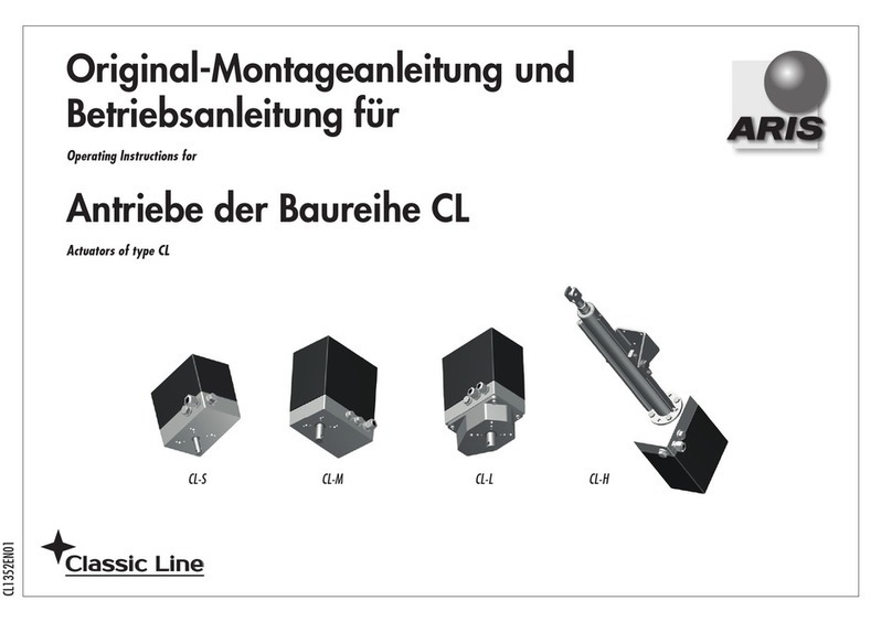
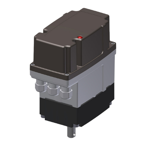
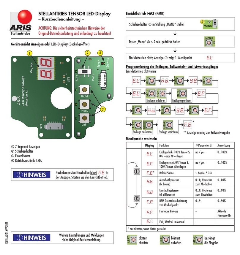
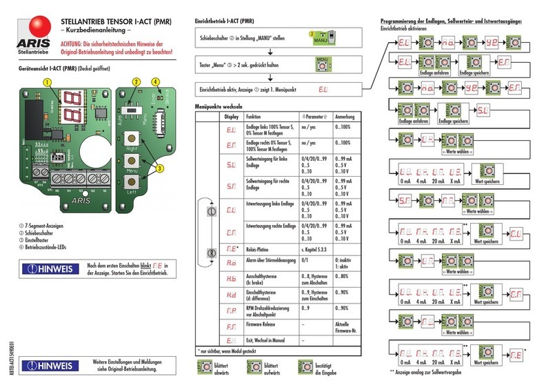
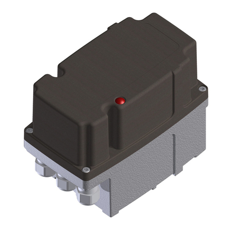
ARIS Tensor2 User manual

Original declaration of
incorporation with manual for
ARIS actuator
Tensor2
Tensor2Highspeed
Tensor2+ (Option)
Tensor2+ Zone 2/22 (Option)
TE22138EN01
Stellantriebe

Inhaltsverzeichnis
1. Identication..............................................................................................................................................................3
1.1 Nameplate............................................................................................................................................................................................................................ 3
1.2 Guidelines and standards ...................................................................................................................................................................................................... 4
2. Safety information .....................................................................................................................................................4
2.1 Warnings.............................................................................................................................................................................................................................. 4
2.2 General safety advice............................................................................................................................................................................................................ 4
3. Technical specication .................................................................................................................................................5
3.1 Functions and application areas (Intended use)...................................................................................................................................................................... 5
3.2 Safe and accurate use........................................................................................................................................................................................................... 5
3.3 Dimensions........................................................................................................................................................................................................................... 6
3.4 Performance data............................................................................................................................................................................................................... 12
3.5 Expected lifespan and intended disposal .............................................................................................................................................................................. 12
4. Actuator setup for utilization ....................................................................................................................................13
4.1 Transport, (temporary) storage and downtimes.................................................................................................................................................................... 13
4.2 Packaging .......................................................................................................................................................................................................................... 13
4.3 Safe disposal of packaging.................................................................................................................................................................................................. 13
4.4 Installation and mounting ................................................................................................................................................................................................... 13
4.5 Initial operation.................................................................................................................................................................................................................. 14
5. Actuator operation without modules (Standard) .........................................................................................................16
5.1 Operation........................................................................................................................................................................................................................... 16
6. Additional advice concerning the intended use in potentially explosive atmospheres of the zone 2 and 22 (Option).........33
6.1 Nameplate.......................................................................................................................................................................................................................... 33
6.2 Guidelines and standards .................................................................................................................................................................................................... 34
6.3 Technical specications........................................................................................................................................................................................................ 34
6.4 Performance data............................................................................................................................................................................................................... 35
7. Additional options ....................................................................................................................................................36
7.1 Internal manual override (mechanical)................................................................................................................................................................................ 36
7.2 Option hand wheel.............................................................................................................................................................................................................. 36
8. Parameter RESET......................................................................................................................................................36
9. Required customer information..................................................................................................................................37
9.1 Troubleshooting and repair.................................................................................................................................................................................................. 37
10. Maintenance ............................................................................................................................................................38
10.1 Service............................................................................................................................................................................................................................... 38
10.2 Accessories ......................................................................................................................................................................................................................... 38
10.3 Spare parts......................................................................................................................................................................................................................... 38

3Tensor2
1. Identication
This manual is valid for:
Description: Electrical actuator
Type: Tensor2(and add-ons), Tensor2Highspeed
Serial no.: YYWW-xxxxx-01001 ff.
1.1 Nameplate
ARIS Stellantriebe GmbH
Rotter Viehtrift 9
D-53842 Troisdorf
www.stellantriebe.de
SNr: YYWW-XXXXX-01001
Typ: Tensor2
85...265 V AC, 50/60 Hz
60s/90°, 15 Nm, 20 VA
UT -15°C/+60°C IP65
Made in
Germany
Stellantriebe
Serial number (YYWW= year of manufacture+week)
Actuator type
Voltage/Frequency (DC as an option)
Actuating time/Torque/Power consumption
Ambient temperature/Protection class

4Tensor2
1.2 Guidelines and standards
ARIS actuators are partly completed machinery according to directive 2006/42/EC.
Further applicable EC directives: EMC Directive 2014/30/EC DIN EN 61000-3-3
DIN EN 61000-6-2
DIN EN 61000-6-3
DIN EN 61000-6-4
DIN EN 55011
Applied harmonized standards: LVD Directive 2014/35/EC DIN EN 61010-1:2011-07
MachDir 2006/42/EC DIN EN 12100:2011-03
Protection class by enclosure (IP-Code) Protection class testing DIN EN 60529:1991
EMC considerations of the overall system and system perturbations and their combating
have to be treated by the system manufacturer or system operator. The wiring of the
actuator should be carried out in accordance with DIN EN 60204-1.
2. Safety information
2.1 Warnings
Installation and initial operation only by certied experts according to this manual.
Observe the signicance of the following symbol and note explanations. They are subdevided in security levels and classied
according to ISO 3864-2.
DANGER indicates a hazard with a high risk degree, which, if not avoided, causes death or
heavy injuries.
WARNING indicates a hazard with a medium risk degree, which, if not avoided, can cause
death or heavy injuries.
CAUTION indicates a hazard with a low risk degree, which, if not avoided, can cause slight
or moderate injuries.
Indicates general advice, useful hints and work recommendations, which don´t have
inuence on the safety and health of the staff.
2.2 General safety advice
The actuator components are conform to the state of the art and apply as generally safe at the time they are shipped.
This manual serves as basis to install and operate ARIS actuators safety conform. All persons working with or on ARIS actuators
must observe this manual and especially its safety advice.
• This manual has to be kept at the operating site at any time.
• Read the manual carefully prior to installation and initial operation.
While operating electronic devices certain parts are obligatory under hazardous voltage.
DANGER
ADVICE
!
CAUTION
WARNING
ADVICE
!
WARNING
ADVICE
!

5Tensor2
• Working on electric appliances or equipment is only allowed for electrically qualied persons or other instructed persons
under guidance and custody of an electrically qualied person according to the electro-technical regulations.
• Observe all safety and accident prevention regulations while installing, operating and testing any electrical appliances or
machinery.
• Prior to all installation or regular work on the actuator make sure to switch off all connected machinery/appliances.
3. Technical specication
3.1 Functions and application areas (Intended use)
ARIS actuators are exclusively designed for industrial use. ARIS actuators are utilized for operating regulating and shut-off applian-
ces (valves, ball valves, taps, slide valves, dosing pumps, etc.).
ARIS actuators may not be used for:
• Temperatures below or above the specied data
• Underground environments
• Near open res
• Under water
3.2 Safe and accurate use
ARIS actuators are factory checked prior to delivery. The nal functional testing must be performed within the nal system by
qualied technical personnel.
The ARIS company assumes no liability for any direct or indirect damage arising from
• an insufcient test period of the actuator in the nal system,
• an improper utilization of the actuator,
• a further utilization after an error was detected.
Perform controls on a regular basis during the operation. Pay particular attention to:
• intended utilization of the actuator (Chapter 3.1);
• unusual sounds, severe vibrations or increased temperatures;
• examine the correct tightening torque and impermeability of xing screws, cable entries, cable glands and sealing plugs;
• the condition of the electrical lines.
In case of malfunctions, you have to stop the actuator and remedy the malfunction.
All persons who work on installation, commissioning and setting must
• be specially trained and qualied;
• be mentally and physically capable;
• observe the operating instructions.
• Valves, levers and connecting rods are moving during actuator operation.
• Check for proper function of all emergency equipment on your machinery/system.
• Check for proper function of the actuator and operated valves after completion of all installation work.
• Never work with or operate a faulty actuator.

6Tensor2
3.3 Dimensions Tensor2S
153
866360
F05 50
F03 36
65
50
M6x9
M6x9
M5x9
P12
6
40
11
11Q
40
16
3
P12
4
42
P
5
T=2.5
25 25
8
P10
35
25
D-Shaft
(Option)
Round shaft
w/feather key
(Option) ISO shaft
4-square
(Option)

7Tensor2
Tensor2S Highspeed
46
180
40
50
65
M8x12
M6x12
M6x12
F07 70
F05 50
40
6
P12 h9
P
5
20
31 31
3x M20x1.5
155
100
11Q
11
25
35
P10
8
16
P12
4
3
40
D-Shaft
(Option)
Round shaft
w/feather key
(Option)
ISO shaft
4-square
(Option)

8Tensor2
Tensor2M
153
86
25
25
F07 70
F05 50
50
M6x11
M8x12
M6x11
63
4060
82
16
14Q
65
40
40
L
3
D
P
TypeD B L P T
30
-
40 Nm 12 5 16 4 2
.
5
50
-
75 Nm 14 6 22 6 3
D
B
6
T
25 25
Round shaft
w/feather key
(Option)
ISO shaft
4-square
Round shaft
w/cross hole
(Option)

9Tensor2
Tensor2M Highspeed
155
100180
40
40
20
31 31
3x M20x1.5
86
50
65
M8x12
F07 70
M6x11
M6x11
F05 50
14
Q
16
TypeD B L P T
30
-
40 Nm 12 5 16 4 2
.
5
50
-
75 Nm 14 6 22 6 3
D
P
3L
40
B
D
6
40
T
Round shaft
w/feather key
(Option)
ISO shaft
4-square
Round shaft
w/cross hole
(Option)

10 Tensor2
Tensor2L
153
86
42
F07 70
25
25
M8x16
60
63
63
45
10
P20
P8
17Q
21
45
3
22
6
P20
T=3.5
25 25
Round shaft
w/feather key
(Option)
ISO shaft
4-square
(Option)

11Tensor2
Tensor2L Highspeed
100
155
63
180
40
20
31 31
M8x16
F07 70
46
3x M20x1,5
45
10
P
8
P20
21
174kt SW
45
22
P20
6
3
t=3,5
Round shaft
w/feather key
(Option)
ISO shaft
4-square
Round shaft
w/cross hole
(Option)

12 Tensor2
3.4 Performance data
3.4.1 Actuator specications
3.5 Expected lifespan and intended disposal
ARIS actuators have an expected lifespan of several years, depending on their utilization and application. No longer usable actu-
ators must not be dismantled in whole, but separately recycled in parts divided by their materials. Non-recyclable components
must be disposed according to national disposal regulations.
Voltage supply 85…265 V AC (50/60 Hz) / 19.2…28.8 V DC
Protection class IP65 (IP 66/IP 67 Option)
Motor BLDC-Motor
Connection Tensor2: 3 cable entries M16x1.5 (provided by customer)
Tensor2HS: 3 cable entries M20x1.5 (provided by customer)
Position feedback Digital via magnet sensor
Ambient temperature -15 °C bis +60 °C (other temperature ranges optional)
Installation position Arbitrary
Potentiometer (Option) Electronical
Travel >28°…100 revolutions
Operation Onboard: 3 buttons (Left / Menu / Right), 1 slide switch (AUTO / MANU)
External: 4 buttons (Left / Menu / Right / Mode)
Display OLED-Display 0.96"

13Tensor2
4. Actuator setup for utilization
4.1 Transport, (temporary) storage and downtimes
Use the factory packaging for transport to the installation point.
Replace a damaged original packaging by a new solid packaging.
• Actuators with attached valves: Attach lifting gear only on the valve and NEVER on the actuator;
• Do not use ARIS actuators as a climbing or support aid;
• ARIS actuators must not operate in unsecured lifting operations without additional applications.
Possible damage by wrong storage.
• Store in well-ventilated rooms;
• Protection against possible ground humidity (shelf storage);
• Add moisture-absorbing agents to the actuator during longer periods of storage;
• Protect the actuators from dirt and dust;
• Take measures for prevention of condensation (e.g. at temperature uctuations).
4.2 Packaging
ARIS actuators are protected by special cardboard packaging on delivery.
4.3 Safe disposal of packaging
Additionally necessary packaging is made by easily separable packaging materials and can be recycled individually:
• Wood
• Cardboard
• Paper
• Plastics
4.4 Installation and mounting
• Inspect the actuator for damages prior to installation;
• the screw-in depth of connecting thread holes must not exceed 9 mm;
• check leak tightness of cable glands and blank plugs prior to initial operation;
• tighten the cover screws evenly (max. 1.2 Nm);
• do not operate before limit switches have been adjusted;
• protect the actuator against climatic inuences (e.g. by a protective cover);
• do not expose the actuator to hard shocks (e.g. by dropping);
• do not attach ropes, hooks or the like to the actuator;
• permanent overload and blocking leads to actuator damages;
• use only ARIS original spare parts.
ADVICE
!

14 Tensor2
Consider prior to attachment of couplings:
• Do not turn actuator shafts by force;
• actuator and valve shafts must run centric.
For all actuators observe the following advice:
The initial operation of the actuator is only permitted with orderly closed cover and closed cable entries. Use only cable glands
which are appropriate for the respective protection class.
• Cable entries
Ensure that all cable entries are closed properly during storage, installation and initial operation.
Use only cables which are suitable for the diameter of the cable entries.
• Cover assembly
During the cover assembly make sure that the cover ts correctly.
The cover must not show any damages on the joint surface.
Tighten cover screws evenly (max. 1.2 Nm).
No additional bores are allowed to the enclosure and the cover.
4.5 Initial operation
4.5.1 Electrical connection
Hazardous voltage: Possible stroke!
• The initial operation must be carried out only by experts!
• De-energize the actuator before opening.
• Observe the appropriate regulations during electrical installation and initial
operation.
Connect the actuator as follows (wiring diagram see chapter 4.5.2):
• Connect the ground wire of the electric supply to the appropriate protective earth terminal.
• Always refer to the wiring diagram located inside the actuator.
Check prior to initial switching on:
• Is the actuator undamaged on the outside?
• Is the mechanical connection correct?
• Has the electrical connection been made regularly?
• Check if current type, voltage and frequency match with the motor data (see nameplate on cover and inside the actuator).
• Insert suitable cable glands for the connection line.
• Use separate (shielded) wires for low voltages.
• Set up limit switches prior to initial operation.
CAUTION
WARNING

15Tensor2
4.5.2 Wiring diagram
Connection 85…265 V AC
N Neutral conductor
L Phase / Supply 85 ... 265 V AC
2 Control connection > left-turning (CCW)
3 Control connection > right-turning (CW)
Connect the ground wire to the inside of the housing.
Connection 19.2…28.8 V DC
– GND
+ Connection 19.2…28.8 V DC
2 Control connection > left-turning (CCW)
3 Control connection > right-turning (CW)
The control terminals "2/3" are only active if the "Signal In"-Option "Terminal 2/3" has
been chosen in the Expert Menu.
The drive must be permanently energized, otherwise the holding torque is not available!
ADVICE
!
CAUTION
-/N +/L 2 3
2 3
L R
-/N +/L PE

16 Tensor2
5. Actuator operation without modules (Standard)
5.1 Operation
(1)
The Tensor2is operated via 3 buttons and a slide switch, located above the actuator´s display. The OLED display makes setting up
the actuator easier by showing text such as letters, numbers and signs.
Navigate between different menu items by using the buttons LEFT [L] & RIGHT [R].
5.1.1 Buttons and switches
The buttons (1) are indicated with
LEFT [L]
MENU [M]
RIGHT [R]
The functionality of the buttons is explained in section "Operating modes".
5.1.2 Operating modes
The different operating modes of the actuator can be selected via the slide switch resp. the MENU button. The actual operating
mode is shown on the display.
(1)
The Tensor
2
is operated via 3 buttons and a slide switch, located above the actuator´s display. The OLED display makes setting up
the actuator easier by showing text such as letters, numbers and signs.
(1)

17Tensor2
Automatic operation (AUTO mode, switch position "AUTO"):
The actuator runs with an external signal, which is present depending on the setting on the terminal clamps, the signal clamps or
CAN clamps. The onboard buttons are without function.
Manual mode (MANU mode, switch position "MANU"):
The actuator can run left and right by using the buttons "L" & "R", if the actuator is not in setup mode. Change to setup mode by
pressing the MENU button longer than >1s.
Setup mode (Switch position "MANU"):
Different actuator parameters can be set up and adjusted.
Start setup mode:
1. Slide switch to position"MANU"
2. Press button MENU longer than >1s
Setup mode is turned on and the rst menu item "MAIN MENU" is displayed.
Within the setup menu navigate between different menu items and adjustments by pressing the buttons "L" & "R".
Conrm any entry by pressing the MENU button (press <0.5s).
Exit any menu item by pressing the MENU button longer than >1s.
Exit setup mode:
Exit the setup mode by moving the slide switch to position "AUTO" and conrming the notication message.
Alternatively press the MENU button in the top menu layer longer than >1s and conrm the notication message. The actuator
then changes to manual mode (MANU mode).
A warning message is displayed when switching between different operating modes,
because the actuator can run under certain conditions. Conrm the message with the MENU
button.
The actuator may run and move the connected valve when switching from MANU to AUTO
and you conrm the warning message.
After switching from MANU to AUTO and conrming the warning message the actuator can
be operated by using the buttons "L" & "R".
ADVICE
!
Setup mode is turned on and the rst menu item "MAIN MENU" is displayed.
WARNING

18 Tensor2
5.1.3 Menu system overview
Menu items
Depending on the selected user, stored access authorisation, set parameters and the model type of the actuator, single menu items
may be invisible/hidden differing from the following overview.
x = menu item visible
Menu Sub item Function
Standard
POTI (Potentiometer)
A-OUT (Analog output,
Current/Voltage output
CONTROL (Controller, i-Act)
MAIN MENU Main Menu
XLOGIN Login (Select user)
End positions Set up end positions (Left & right)
Poti input Settings for operating the actuator
via external potentiometer X
Poti output Settings for potentiometer output values
(Feedback) X X
Set value Settings for set value defaults
(Drive via set value) X
Actual value Settings for actual value output
(Feedback current/voltage) X X
Relay switch Programming relays behaviour
(Option board)
visible only with attached relays module
(Option board)
EXPT. MENU Expert Menu
XSignal IN Selection of input signal for driving the actuator
Signal OUT Selection of output signal for position feedback
Wire monitor Setting of actuator behaviour in case of cable breakage
(formerly wire break monitoring) X
Status info Activate/Deactivate message output X X X
Offset Settings for allowed control deviation in controller mode X

19Tensor2
Hyst. Start Dene start hysteresis
X
Hyst. Stop Dene stop hysteresis
Stall-det. Settings for block detection
Block-det. Settings for block detection near the end positions
RPM acc. Dene acceleration ramp of actuator
RPM red. Dene break ramp of actuator
Add feature Entry of activation code for function extensions
POWR. MENU Power Menu
X
Torque/Speed Selection of a torque/time combination
for CCW resp. CW rotation
INFO MENU Information Menu
X
Firmware Indicates rmware revision
Hardware Indicates hardware revision
Serial-No. Indicates serial number of the electronics
Features Indicates unlocked actuator functions
On-time Indicates operating hours of the actuator
Cycl. Count Indicates number of starts of the actuator
Modules Indicates connected modules/option boards
Menu items in detail
MAIN MENU
Login Enables selection of an access level. If a password has been stored, enter it here to proceed to further menu items.
Depending on the selected access level, single menu items may not be visible or adjustable.
If the login is missing, only the INFO MENU and the menu item LOGIN (in MAIN MENU) are visible.
The following users are selectable:
• User
• Service
• Manufacturer (ARIS only)
A logged in user can be logged out via the menu item "Logout".

20 Tensor2
Login
(Contd.)
A user has to be selected/logged in on initial switch on or after a voltage loss, even if no password was given for the
selected user.
If no password was stored for the user, the password entry is skipped and the rst menu item will be displayed.
Password entry:
• Select the appropriate gure via buttons L & R (actual gure is ashing)
• To edit the gure press the MENU button --> An underscore is shown below the gure.
• Set selected gure by using buttons L & R.
• Conrm the set gure with the MENU button.
• Navigate to the conrmation arrow after password entry and conrm with the MENU button.
No error message is shown when entering a wrong password. A correct password or the active user is marked with an
asterisk (*) behing the selected user.
Example with user "User":
Password correct/User active: > User*
Password wrong/User inactive: > User
End positions End positions
Selection and setting of the left (EL) and right (ER) end position.
Approach end positions using buttons L and R and then store them.
Procedure:
• Select the end position to be set
• Within the display "<EL>" or "<ER>" approach left resp. right end position via buttons L & R and conrm with
MENU button
• Accept (Y) or cancel (N) storing the end positions. Change between (Y)/(N) via buttons L & R, conrm selection
with MENU button.
Motor or parts can be damaged when driving against obstacles. The motor does not stop at the prior set end positions
during an end position is re-programmed. Drive the actuator slowly and carefully when setting new end positions.
Left and right end positions can be interchanged. The assignment of the turning direction of the inputs 2/3 and the
buttons LI/RE do not change.
The end positions must be 28° apart due to technical reasons. If the difference range is too small, the actuator will
prompt "Error Code 51".
ADVICE
!
ADVICE
!
CAUTION
This manual suits for next models
3
Table of contents
Other ARIS Controllers manuals

ARIS
ARIS Tensor Zone 2/22 User manual

ARIS
ARIS TENSOR User manual

ARIS
ARIS PD Technical document

ARIS
ARIS LINEARIS User manual

ARIS
ARIS TENSOR I-ACT (PMR) Installation guide

ARIS
ARIS TENSOR Installation guide

ARIS
ARIS SCU5 User manual

ARIS
ARIS Classic Series User manual

ARIS
ARIS Linearis N+ User manual

ARIS
ARIS Nano+ User manual