Arjo Sara 2000 User manual

?!
Sara 2000
Operating Instructions
TM

2
Congratulations on your purchase of the Arjo Sara
2000.
Symbols used adjacent to the text in these
instructions:-
Danger Means:- electrical hazard warning,
failure to understand and obey this
warning may result in electrical
shock.
Warning Means:- failure to understand and
obey this warning may result in
injury to you or to others.
Caution Means:- failure to follow these
instructions may cause damage to
all or parts of the system or
equipment.
Note Means:- this is important
information for the correct use of
this system or equipment.
Contents
A
B
C
D
E
F
G
AParts referred to in these Instructions
1. Adjustable chassis legs
2. Patient foot rest
3. Braked castors
4. Battery compartment
5. Battery pack
6. Knee pad
7. Control handset
8. Manoeuvring handle
9. Leg strap connection knob
10. Leg support straps (with variable
adjustment)
11. Sling attachment clips
12. Patient support arms (with grab
handles)
13. Sling
14. Commode seat attachment
(accessory).
15. Chassis
16. Buttock/leg support
(transfer sling only)
17. Reset button (Green)
18. Emergency stop button (Red)
19. Battery state indicator light
20. Emergency lowering switch
(covered with usage indicator seal)
21. Raise button
22. Lower button
23. Chassis leg opening button
24. Chassis leg closing button
25. Control handset
26. Hanging hook (on back)
27. System overload fuse
(re-settable)
1
12
34
5
6
7
8
9
10
11 12
13
14
15
16
17
18
19
20
21
23
22
24
25
26
Fig. 1
mP1311, P1066/2, P1223, P1067f/2, label
Parts referred to in these instructions (Page 2)
Introduction (Page 3)
Preparation for use (Page 4)
Using your Sara 2000(Pages 5 to 11)
Battery charging (Pages 12 to 13)
Care of your Sara 2000(Pages 14 to 17)
Technical Specification(Pages 18 and 19)
The vertical and horizontal lines printed in the margins adjacent to the
text/illustrations in these instructions are for Arjo use only and should
be disregarded by the reader.
27
Emergency lower
switch label

3
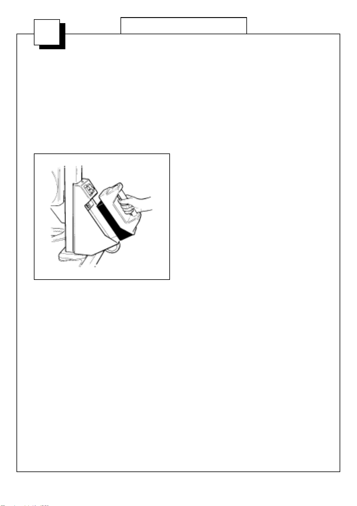
Note: On delivery of your hoist, check that the
usage indicator seal fixed across the emergency
lowering switch (see Fig. 1) is intact. If it is
broken, contact Arjo Ltd or their appointed
distributor, before using the hoist.
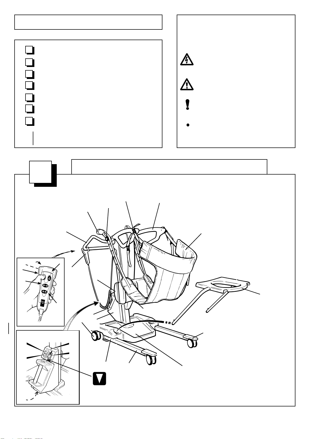
Before using your Sara 2000, familiarise
yourself with the various parts as illustrated in
figure 1, and thoroughly read and understand
these Operating Instructions.
The Sara 2000 is manufactured to a very high standard,
and primarily designed to assist patients when standing
and toileting, and for use as a short distance patient
transfer aid.
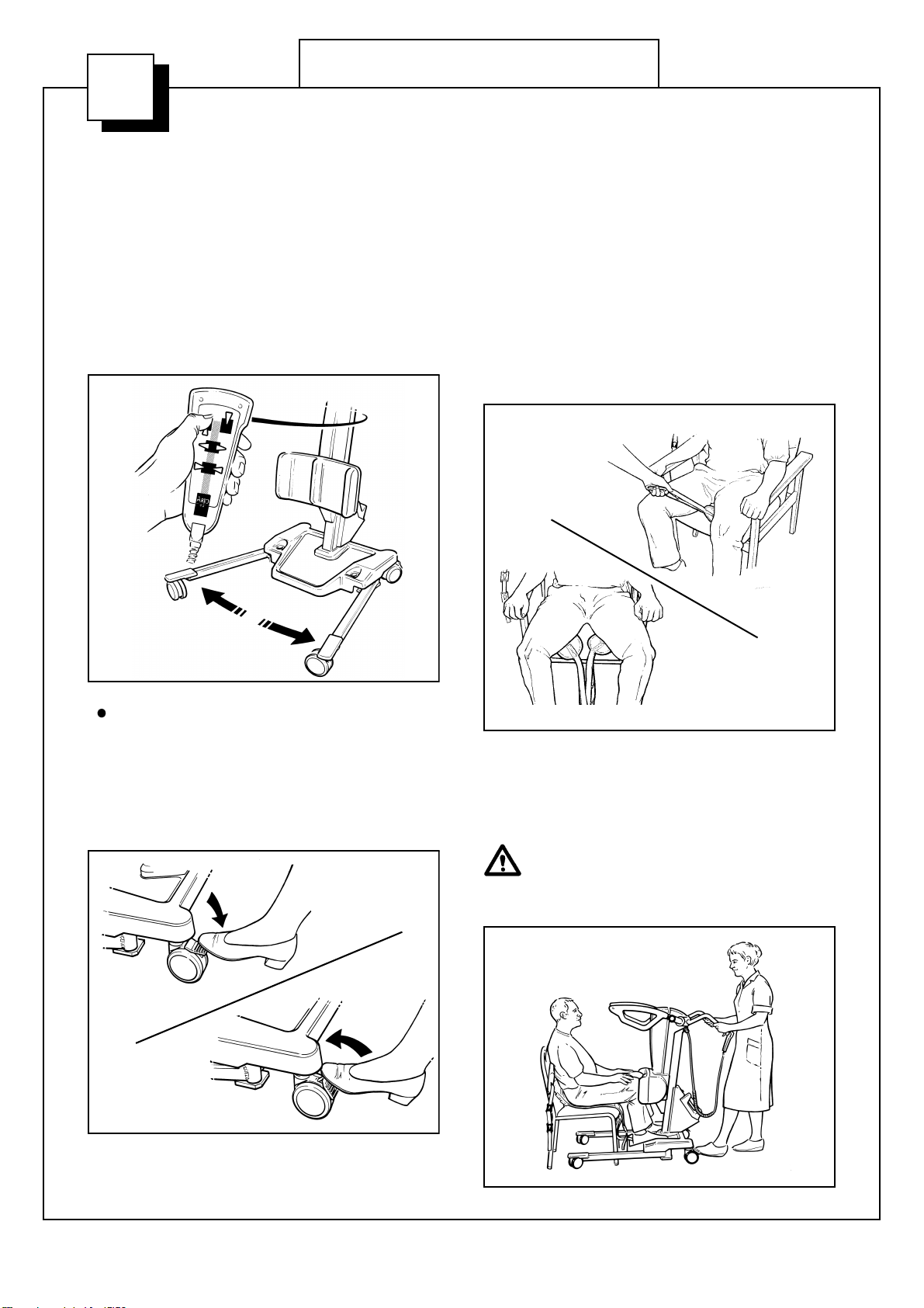
The Sara 2000 is designed for quick easy
transfers from one sitting position to another,
and to elevate a patient for toiletting,
repositioning, changing of incontinence pads,
wound dressings, standing practice etc. It is not
intended for long periods of suspension or
transportation.
This product has been designed and manufactured to
provide you with many years of trouble free use,
however, this product does contain components that
with regular use are subject to wear.
SOME OF THESE PARTS ARE
SAFETY CRITICAL TO THE OPERATION
OF THE HOIST AND WILL NEED
EXAMINING AND SERVICING ON A
REGULAR BASIS AND MUST BE
REPLACED WHEN NECESSARY. See also
“Care of your Sara 2000” section.
All references to the patient in these instructions
refer to the person being lifted, and references to the
attendant refer to the person who operates the hoist.
References to left and right of the hoist in these
instructions are as viewed from the rear of the
Sara 2000.
Use only Arjo slings that have been specifically
designed for the Sara 2000.
Two types of sling can be used with the Sara 2000.
•Standing Sling - a single loop sling, used for
supporting patients at the toilet, and to aid in
the standing process. This is a one size sling,
with variable adjustment using the different
attachment clips.
•Transfer Sling - a single loop sling with buttock
and leg support, used for easy and comfortable
transporting of patients over short distances.
The sling has variable adjustment using the
different attachment clips and leg strap loops,
(these being colour coded to relate them to the
size of patient to be lifted).
Commode Seat (accessory) - for toileting patients at
the chair side, or for patients who cannot be
transported. The assembly comprises an easy to fit
rigid commode seat, with removable commode pan.
It is available from Arjo as an accessory.
Do not overload the Sara 2000 with a weight in
excess of the approved lifting capacity of 180kg
(400lbs).
The commode and seat (accessory) has a
maximum weight limit of 160kg (350lbs) which
must not be exceeded, so allowance must be
made if using this facility.
The Sara 2000 may be used on gentle slopes
with caution.
Care should be taken when lifting detachable
components e.g. toilet seat, so as not to cause
personal injury.
Do not attempt to manually lift the complete
hoist.
A clinical assessment should be carried out by
a qualified nurse or therapist before lifting
patients who are non weight bearing. This
also applies to patients who have limited
shoulder movement or cannot hold on with
one or both hands.
Patients who have curvature of the spine, or
who are subject to muscle spasms may not be
suitable, and should be carefully assessed
before proceeding with the lift.
Although manufactured to a high standard
the Sara 2000 and accessories should not be
left for extended periods in humid or wet
areas.
Do not under any circumstances spray the
Sara 2000 or accessories (excluding slings)
with water e.g. under the shower.
Some information contained in these instructions may
become outdated, due to improvements made to this
product in the future. If you have any questions
regarding these instructions or your hoist, please
contact Arjo or their approved distributor.
Arjo’s policy is one of continuous development, and
therefore reserve the right to change specifications
without notice.
BIntroduction

4
CPreparation for Use
Before commencing to lift the patient, ensure that all
the actions and checks in this Preparation section are
carried out.
Unpack the battery pack supplied, and fully charge
it as described in “Battery Charging section”.
When the battery pack is charged, disconnect the
mains power, then remove the pack from the charger
and insert it fully into the Sara 2000 battery
compartment, located at the lower rear of the mast.
(See fig. 2). Electrical connection is made
automatically.
Ensure that the green reset button, (situated at the
top of the battery compartment), is pressed in. (See
inset to fig 1).
Your Sara 2000 is now ready for use.
P.1067g
Fig. 2

5
Using your Sara 2000
D
Before approaching the Patient
The attendant should always tell the patient what
they are going to do, and have the correct size sling
ready.
Ensure the patient support arms are raised or
lowered sufficiently to avoid approaching the
patient at eye level.
If required, the chassis legs may be opened to go
around the chair, by operating the appropriate button
on the control handset. (See fig. 3).
Note: If the handset button is released during
any function, powered motion will stop
immediately.
The chassis rear castors have brakes which can be
foot operated if required, (see fig. 4), for example,
when leaving the patient unattended, or to keep the
Sara 2000 in position.
Using the Sara 2000 Slings
Select which sling will be required. (See the
description of sling types in the ‘Introduction’
section).
Transfer Sling
With the patient in a sitting position, place the sling
around the patients back, so that it lies
approximately across the shoulder blades, with the
patients arms outside the sling.
Bring the buttock / leg pieces of the sling carefully
under the patient in readiness for connection,
ensuring the pieces are not twisted. (See fig. 5).
Bring the Sara 2000 carefully up to the patient,
placing the patient’s feet on the footrest, continuing
forward, if possible, until the kneepad is just in
contact with the patients knees and upper shins. Put
on the brakes. (See fig. 6).
When moving the Sara 2000 close to the
patient, care must be taken to ensure the
patient’s feet are not positioned between the
footrest and floor.
mP1312, mP1063e, P1223
Fig. 3
Fig. 4
mP1313, P1067b,d
Fig. 5
mP1314, mP1043c,d
Fig. 6
P.1065b/2
continued .....

6
Lower the support arms carefully using the control
handset, until the sling attachment lugs on the
support arms are close enough to connect up one of
the sling attachment clips. (See fig. 7).
Next, select the appropriate clip on the opposite end
of the sling and connect up.
Note: The patient should be supported by the
sling, but not pulled forward too much.
Note: Clip selection is at the discretion of the
attendant, and should be relative to the size of
the patient.
Connect the leg straps onto the leg connection
knobs, (see fig. 8), once again by selecting the
appropriate strap loop according to the size of
patient to be lifted. Select one of the three colour
coded loops to the outer end of the straps, ensuring
the same colour loop is used on each side. The leg
pieces should be pulled tight, but still be
comfortable for the patient.
Ensure the sling clips are pulled well down
onto the attachment lugs and secure, and
that the leg pieces are correctly attached,
before attempting to lift the patient.
If possible, the patient should now hold onto the
grab handles with one or both hands.
(See fig. 9).
IMPORTANT: Always check that the sling
attachment clips are fully in position before
and during the commencement of the lifting
cycle, and in tension as the patient’s weight
is gradually taken up.
Encourage the patient to assist all he / she can to
raise from the chair, steady themselves, and to keep
their head back. Operate the control handset to raise
the support arms, this will elevate the patient.
Note: If the handset button is released during
lifting or lowering, powered motion will stop
immediately.
mP1316, P1063a, P1042a
Fig. 7
Fig. 8
P.1065d
P1065c/2
Fig. 9
DUsing your Sara 2000 - continued
continued .....

7
Raise the patient up, until they are supported in a
sitting position - their feet being supported on the
footrest. (See fig. 10).
Note: Be careful not to raise the patient too
high, as this will negate the comfort of the
transfer sling.
Release the brakes, and transport the patient to the
new position, i.e. wheelchair, bed, etc.
Note: Transportation is possible with the
chassis legs open or closed, but will be easier
through doorways etc., with the chassis legs
closed.
When the patient is seated in the new position, and
you wish to remove the sling, unloop the leg support
straps, unclip the shoulder support attachment clips,
and remove the sling from around the patient.
If the patient lacks sitting balance, and has
been returned to the bed on the Sara 2000,
a second attendant may be needed to
support the patient while the sling is being
removed. (See fig. 11).
P.1065e
Fig. 10
P.1065f
Fig. 11
continued .....
DUsing your Sara 2000 - continued

8
Standing Sling
Position the sling around the patient’s back so that it
lies 50mm (2 inches) or so, horizontally above the
patient’s waistline, with the patient’s arms outside
the sling. Ensure the support strap, (if fitted), is
separated, brought loosely around the body, and is
not twisted or trapped behind the patient’s back.
Fasten the support strap, (if fitted), securely. The
strap should be tight, but comfortable for the patient.
(See fig. 12).
Note: The support strap will assist in
supporting the patient in the sling during the
lifting procedure.
Bring the Sara 2000 carefully up to the patient,
placing the patient’s feet on the footrest, continuing
forward until the kneepad is just in contact with the
patient’s knees and upper shin. Put on the brakes.
(See fig. 13).
Lower the support arms carefully, using the control
handset, until the sling attachment lugs on the
support arms are close enough to connect up to one
of the sling attachment clips. (See
fig. 14).
Next, select the appropriate clip on the opposite end
of the sling and connect up.
Note: Clip selection is at the discretion of the
attendant and should be relative to the size of
the patient.
The patient should be supported, but not
pulled forward too much.
Ensure the sling clips are pulled well down
onto the attachment lugs and secure, before
attempting to lift the patient.
If possible, the patient should now hold
onto the grab handles with one or both hands. (See
fig. 15).
P.1067a
Support strap - if fitted
Fig. 12
P.1064a
Fig. 13
P.1063d
Fig. 14
P.1063c
Fig.15
DUsing your Sara 2000 - continued
continued .....

9
IMPORTANT: Always check that the sling
attachment clips are fully in position before
and during the commencement of the lifting
cycle, and in tension as the patient’s weight
is gradually taken up.
Encourage the patient to assist all he / she can to
achieve a standing position, and to keep their head
back.
Operate the control handset to raise the support
arms. This will elevate the patient into a near
standing position, their feet being supported by the
foot rest. (See fig. 16).
Note: If the handset button is released during
lifting or lowering powered motion will stop
immediately.
If the patient can stand sufficiently well to lock his /
her knees in the normal way, their knees will come
away from the reaction pad, and he / she can just
lean back into the sling. (See fig. 17).
If the patient is “slumped”, he / she can still lean
back into the sling, and be kept in the raised position
by the knees being in contact with the kneepad. (See
fig. 18).
Patient’s who have suffered a “stroke”, who can
only hold on with one hand, or patient’s who cannot
hold on at all, may still be lifted by the Sara 2000,
but it will be necessary for the attendant, (or a
second attendant), to hold the patient’s arm / arms
down in front of the body during the lift. (See fig.
19).
Only use this method after a satisfactory
professional assessment has been carried
out on the individual patient.
P.1064b
Fig. 16
P.1064d
Fig. 17
P.1064c
Fig. 18
DUsing your Sara 2000 - continued
continued .....

10
Patient’s wearing nylon nightclothes /
dressing gowns are prone to be “slippery” -
the sling may ride up the back, causing
slight pressure under the arms. It may be
necessary to hold the sling in position when
lifting or lowering.
Release the brakes, and transfer the patient to new
position, i.e., toilet, wheelchair, chair, bed, etc.
Note: Transportation is possible with the
chassis legs open or closed, but it will be
easier through doorways etc., with the chassis
legs closed.
While the patient is raised, make any necessary
adjustments to clothing, incontinence pads etc.,
before lowering again. Lower the patient carefully
using the control handset.
Apply the chassis brakes if leaving the
patient at the toilet, or if leaving the patient
unattended.
When the patient is seated in the new position, and
you wish to remove the sling, unclip the shoulder
support attachment clips, then release the support
strap.
Do not attempt to release the support strap
while the patient is supported by the sling.
Remove the sling from the patient.
If the patient lacks sitting balance and has
been returned to the bed on the Sara 2000,
a second attendant may be needed to
support the patient while the sling is being
removed. (See fig. 11).
Commode Seat (Accessory)
For toileting patients at the chair side or for patients
who cannot be transported, the use of the commode
seat and frame is an easy alternative. The commode
frame is inserted into the holes in the chassis at
either side of the footrest, (see figs 1 and 20), once
the patient has been lifted to a standing or near
standing position in the manner previously
described.
Removal of any clothing can be attended
to, and the patient is then lowered down
onto the commode seat. It is recommended
that the patient is kept supported by the
sling. The retractable commode pan,
accessible from the rear of the seat, (see fig.
20), may be utilised, or removed to enable
the patient to be positioned over a toilet.
Apply chassis brakes if leaving the patient
unattended.
Fig. 19
P.1065a
P.1063f
Fig. 20
DUsing your Sara 2000 - continued
continued .....

11
Emergency Lowering
In the unlikely event that the control handset fails to
operate the hoist, with a patient still supported by
the sling, provision for lowering has been made,
using the “emergency lowering switch”, situated at
the top right of the battery compartment.A label
situated below the switch is for quick and easy
recognition (See fig. 21). If pressure is released
from the switch during use, lowering will stop. Only
use this switch in an emergency, do not use it for
normal function lowering.
The emergency lowering switch will only
operate while the green reset button is in.
The “automatic stop function” of the jib
will not operate while using the emergency
lowering button, so caution must be
exercised if this facility has to be used.
If the emergency lowering switch has to be
operated, the usage indicator seal will be
broken, this identifies that the switch has
been used, the hoist must then be
withdrawn from use immediately and the
Arjo Servoice Department or their
appointed distributor contacted.
Emergency Stop Button
If, in an emergency, you have to immediately stop
any powered movement, (other than by releasing
pressure on the control handset button), press the
“emergency stop button”, situated at the top left of
the battery compartment. (See fig. 21).
Once the emergency stop button has been operated,
the green reset button will have to be re-engaged by
pressing it in, before any powered movement can be
utilised.
System Overload Fuse (resettable)
If the chassis legs (open/close) function or the lifting
arms (raise or lower) function fail to operate when
pressing the appropriate button on the control
handset:-
Check that the ‘Green’ reset button is pressed in and
check the battery pack is in a good state of charge, if
the functions still fail to operate, check the system
overload fuse (situated under the battery
compartment). If the fuse has operated the switch
section will protrude from its mount, press the
switch in to reset. If the ‘cut out’ operates again
withdraw the hoist from use and contact Arjo
Service Department.
General Information
If the Sara 2000 is being used for “standing
practice”, (accustoming the patient to the upright
posture after long periods in bed), or for other
reasons of instability, keep the sling sufficiently
tight to give support, but without restricting
movement.
Note: The Sara 2000 is designed for quick,
easy transfers from one sitting position to
another, and to elevate a patient for toileting,
repositioning, changing of incontinence pads,
wound dressings, standing practise, etc.
The Sara 2000 is not intended for long
periods of suspension.
Emergency
stop button
Reset
button
Battery state
indicator
light
Emergency
lowering
switch
(covered with usage
indicator seal)
P.1067f/2
Fig. 21
System
overload
fuse
(resettable) Emergency
lowering label
DUsing your Sara 2000 - continued

12
Battery Charging
The Sara 2000 incorporates a battery state indicator
light, situated on the top of the battery compartment
(see fig. 1). This light will flash intermittently when
the battery pack needs recharging, and, although a
small number of lifts are possible when the light
flashes, it is a signal that the pack needs to be
charged as soon as possible.
To ensure the Sara 2000 is always ready for use, it is
recommended that a freshly charged battery pack is
always available. This is achieved by having a
second battery pack available, and keeping one on
charge while the other is in use.
Recharging the battery pack before it is
totally discharged will prolong its life.
When the battery state indicator light flashes,
complete your lift / lower cycle, then pull out the
battery pack from the battery compartment
carefully.
Hold the pack firmly to ensure it does not
drop and become damaged, or cause
personal injury.
Place the battery pack on charge as follows:
Ensure the mains power is switched off.
Insert the battery pack into the charger unit and push
firmly in, the charging connector will automatically
couple, then switch on the mains power. A green
light and an orange light will then be displayed (the
green light indicates that mains power is connected,
and will stay on until the mains power is
disconnected. The orange light indicates battery
state and will go out when the battery pack is fully
charged) (see fig 22).
Note:The battery pack may be left connected
to the charger unit when it is fully charged
without being damaged by overcharging, this
will also ensure the battery is kept fully
charged.
Always disconnect the mains supply before
disconnecting the battery.
When the battery pack is fully charged, disconnect
the mains power, remove the pack from the charger,
and insert it fully into the battery compartment.
Electrical connection is made automatically.
Ensure the green reset button (situated at the top of
the battery compartment) is pressed in (see figs. 1
and 21).
The Sara 2000 is now ready for use.
P1052
‘Power On’ indicator light
‘Batttery State’ indicator light
Fig. 22
Battery Charging
E
(continued...)

13
Warnings
Only use the charger unit in a dry
environment, do not use it in the bathroom.
Do not expose the charger unit or battery
pack to rain or spray and do not immerse in
water.
Do not obstruct ventilator slots on the
battery charger otherwise overheating will
result.
No smoking or naked flames in battery
vacinity.
The battery charger is for use only with
Arjo supplied batteries that are to be used
with the Sara 2000.
The battery charger is for use with sealed
lead acid batteries only.
Under no circumstances should the charger
be used to attempt to recharge non-
rechargeable batteries.
To change the power cord, the charger must
be sent to the manufacturer.
General Safety Practices For
Batteries
Only use the charger unit supplied with the
Sara 2000.
Do NOT charge batteries in a sealed
container.
Do NOT place batteries near, or dispose of,
in a fire.
Do NOT short circuit a battery.
Do NOT store batteries at temperatures in
excess of 60°C (140°F).
Do NOT crush, puncture, open, dismantle
or otherwise mechanically interfere with
batteries.
Should the battery casing become cracked,
and electrolyte come into contact with skin
or clothing, wash immediately with water.
If the electrolyte contacts the eyes, wash
immediately with copious amounts of
water, and seek medical attention.
When disposing of batteries, contact the
appropriate local authority for advice.
Storage of Batteries
When stored, a battery will slowly self
discharge. Batteries that are not in use or
recharge should be kept cool but not under
0°C (32°F). Recharge stored batteries
every six months.
EBattery Charging - (continued)

14
How often the following actions are taken depends
on how often the equipment is used.
Unless otherwise stated, it is a good idea to begin
once a week and then rely on experience to decide
how often it is necessary in the future.
The slings should be checked, and if
necessary washed according to instructions
on the sling, also refer to sling instruction
sheet MAX.01520.INT.
With regard to laundering, slings should
not be classified as linen, but as an
accessory to a patient transfer hoist and
therefore classified as a medical device.
Slings should be cleaned and disinfected
only in strict accordance with the
manufacturers instructions.
Mechanical pressure should be avoided
during the washing and drying procedure
e.g. rolling or pressing, as these can
damage parts vital to the safe and
comfortable operation of the sling.
Washing and drying temperatures must
not exceed 80°C (176°F). Wash using
normal detergents, do not iron. Also refer
to Sling Instruction sheet
MAX.01520.INT.
It is recommended that Arjo Patient hoists,
equipment, accessories and slings are
regularly cleaned. If the slings, hoists and
equipment needs cleaning, or are suspected
of being contaminated, follow the cleaning
and/or disinfection procedures
recommended below, before re-using the
equipment. This is especially important
when using the same equipment for
another patient, to minimise the risk of
cross infection.
For cleaning your hoist, equipment and
accessories wipe down with a damp cloth
using warm water to which a disinfectant/
cleaner has been added e.g. “ARJO
CLEAN” - disinfectant/cleaner or
equivalent.
Note:“ARJO CLEAN” - disinfectant cleaner
is available from Arjo Ltd. or their approved
distributors.
Do not over wet areas of the product which
could cause problems with electrical
components or internal corrosion.
If a hot air dryer is used to dry the hoist, the
temperature must not exceed 80°C
(165°F).
Do not use petroleum based solvents or
similar, since this may damage plastic
parts.
For disinfection of contaminated hoists,
equipment and accessories, use the
preferred method of wiping the product
completely with “hard surface disinfectant
wipes” that are supplied impregnated with
a 70% v/v solution of Isopropyl Alcohol.
Note: A rubbing action will be necessary when
using the wipes to promote effective
disinfection of the surfaces.
IMPORTANT: Cleaning and disinfection
products must be used in accordance with
the manufacturers instructions and suitable
eye, hand and clothing protection must be
worn at all times when handling
disinfectants.
Note:70% v/v Isopropyl Alcohol wipes have
been proved to be effective against MRSA and
several other micro-organisms under light
soiling conditions.
Ensure that the battery pack is always in a
good state of charge.
Check that the hoist can be propelled in a
normal manner, making sure that the castors
are quite free in their movement, as clogging
by hair and fluff can occur, also check that the
tread of the castor is not damaged.
Ensure that the castors are firmly secured
to the chassis.
FCare of your Sara 2000
(continued...)

15
Carefully inspect all plastic parts, in
particular where there is personal contact
with the patient’s body, ensure that no
cracks or sharp edges have developed
which could injure the patient’s skin or
become unhygienic.
It is essential that the slings, their straps
and attachment clips are carefully
inspected. If the slings or straps are frayed,
or the clips damaged, the sling should be
withdrawn from use immediately and
replaced.
Check that all external fittings are
secure and that all screws and nuts are
tight.
Ensure that all instruction labels are firmly
attached and in good readable condition.
Periodic Testing
For normal operation - raise and lower the jib using
the control handset, this is to test for full and
efficient movement.
Automatic Stop
With the support arms raised well above their lowest
position, using the control handset lower the support
arms, and at the same time with your other hand
hold the support arms up briefly. (See fig. 23). The
motor will stop while the arms’ weight is held. Stop
the powered movement after a second or two, and
lower the arms carefully. This check is for the
correct function of the automatic stop.
Emergency Stop
Test the emergency stop facility by operating the
control handset to lift or lower the support arms, and
whilst operating, press in the emergency stop
button. (See fig. 21). Powered movement should
stop immediately.
Reset to normal function by pressing the green reset
button. (See fig. 21). Repeat for chassis legs opening
/ closing function, and reset the button.
Adjustable Width Chassis Function
Open and close the chassis legs using the control
handset to check for full and efficient movement.
General Hoist Condition
A general visual inspection of all external parts
should be carried out, and all functions should be
tested for correct operation, to ensure that no
adverse damage has occurred during use.
If in any doubt about the correct
functioning of the Sara 2000, withdraw it
from use and contact Arjo Service
Department.
Fig. 23
P.1067c
FCare of your Sara 2000- (continued)
(continued...)

16
Cleaning and Disinfecting the Toilet
Commode Chair and Frame
For exterior areas of the seat and frame the “hard
surface disinfectant wipes” mentioned above will be
very effective, but for internal and crevice areas of the
equipment Arjo recommend that the seat and frame is
immersed in a disinfectant / cleaning solution and
cleaned in the following manner:-
Note:- “ARJO CLEAN” - Disinfectant / Cleaner
is available from Arjo Limited, or their
approved distributor.
ALWAYS WEAR PROTECTIVE GLOVES
AND EYE PROTECTION WHEN USING
DISINFECTANT.
Always read the instructions on the disinfectant
/ cleaner container before using.
Mix a suitable quantity of solution in the bath tub
(always check dilution rate on disinfectant / cleaner
container).
Remove the plastic commode seat from the seat frame
by pulling the rear edge up sharply to disengage the
locating lugs (see Fig. 24). Slide the seat forwards a
short distance until clear of the frame tubes and lift
away.
Put the seat into the disinfectant solution to “soak” and
then place the seat frame into the bath.
Using an appropriate long handled, stiff bristled,
‘bottle type’ brush, clean the inside of the commode
pan support tubes thoroughly.
Clean the remainder of the seat frame, paying
particular attention to recesses in the framework.
Note:- A scrubbing action is necessary as well
as the disinfectant / cleaner action to sanitise
any surface.
Clean the commode seat, then drain the bath.
Rinse all parts with clean water and dry with a
disposable cloth.
Thoroughly clean the brush in a fresh solution of
the disinfectant/cleaner. Rinse well with clean
water. Dry the brush and store ready for the next
cleaning operation.
To refit the commode seat, locate the seat holes over
the seat frame tubes, and align the location lugs over
the rear cross bar of the seat frame as shown in Fig. 16.
Apply sharp downward blows onto the rear of the seat,
(as shown in Fig.26), in two places directly above the
location lugs, until the seat ‘snaps’ back into place.
Always ensure the seat is secure before
allowing a patient to use it.
P1248c
Fig. 24
P1248a
Fig. 25
P1248b
Fig. 26
FCare of your Sara 2000 - (continued)
(continued...)

17
Servicing Advice
The components listed below are critical to
the safe operation of the hoist and must be
regularly examined and replaced at the
following intervals.
Actuator Pins - Replace every year.
Spare parts, if required are available from Arjo or
their approved distributors.
Special tools are required for certain component
replacement.
The simplest; safest and most effective
way to maintain your product in good
working order, is to have it methodically
and professionally serviced by an Arjo
approved engineer using Arjo approved
spare parts.
For information on service and
maintenance contracts, please contact your
local Arjo distributor.
FCare of your Sara 2000 - (continued)

18
GTechnical Specification
(continued...)
Component Weights
kg lbs
Sara 2000 complete ....................................................................... 60kg (132.3lbs)
Battery pack .................................................................................. 3.8 (8.4)
Electrical
Battery type ....................................................................................(Rechargable-sealed lead acid)
Battery part number........................................................................KKA 1100-04
Battery capacity ............................................................................. 24V 4Ah
Hoist - Protection class................................................................... IPX4
Handset - Protection class ............................................................. IP67
Hoist nominal voltage ................................................................... 24V
Fuse - overload............................................................................... 10A (thermal cutout) -resettable
Medical Equipment:- type protection against electrical shock in accordance with IEC 601-1)
Arjo patient handling products meet the requirements of Electromagnetic Compatibility (EMC) as stated in
clause 12.5 of the Medical Devices Directive 93/42/EEC
Duty cycle Max volts Max amps
Lift Actuator ................................................................................ 10-15% • 6-9min/hr 24 15
Chassis Actuator .......................................................................... 10% • 6min/hr 24 1.85
Environment
Air humidity/storage .................................................................... 20°C (68°f) 80%
Usage temperature (ambient) ....................................................... +10°C (34°f) to +60°C (204°f)

19
GTechnical Specification
All dimensions in millimetres (equivalent in inches)

If your country is not listed here, please contact your local distributor, or Arjo
International AB, Box 61, S-241 21 ESLÖV, S WEDE N .
Tel +46 413 64500. Fax + 46 413 555586.
NEDERLAND
ARJO NEDERLAND B.V.
De Blomboogerd 8
4003 BX TIEL
Postbus 6116
4000 HC TIEL
Tel: 0344 64 08 00
Fax: 0344 64 08 85
E-mail: [email protected]
ÖSTERREICH
ARJO GmbH
Föhrenweg 5
A-6065 THAUR
Tel. 05223 493350
Fax. 05223 49335075
ARJO Poland Sp. z o.o.
ul. Lirowa 27,
02-387 Warsaw,
Poland
tel./fax office: +48 22 882-06-26..28
tel./fax serive: +48 22 882-06-29
SCHWEIZ / SVIZZERA
ARJO INTERNATIONAL AG
Florenzstr. 1d,
Postfach 4023
BASEL
Tel. +41 61 373 26 89.
Fax. +41 61 373 11 00
SCHWEIZ
ARJO-SIC AG
Florenzstr. 1d
Postfach
4023 BASEL
Tel. 0041 61 337 97 77
Fax 0041 61 311 97 42
USA
ARJO, Inc.
50 North Gary Avenue
Roselle, IL 60172
Tel. 1-800-323-1245
Fax. 1-888-594-ARJO(2756)
We strongly advise and warn that only Company Designated Parts, which are designed for the purpose, should be used on equipment
and other appliances supplied by the Company, to avoid injuries attributable to the use of inadequate parts.
The Company’s Conditions of sale make specific provision confirming no liability in such circumstances.
Our policy is one of continuous development, and we therefore reserve the right to change specifications without notice.
AUSTRALIA
ARJO Hospital Equipment Pty. Ltd.
154 Lytton Road
Bulimba
Brisbane
QLD, 4171
Tel. (61) 7 3395 6311
Fax. (61) 7 3395 6712
SCANDINAVIA
Sverige
ARJO SCANDINAVIA AB
Box 61, 241 21 Eslov
Tel. 0413-645 00
Fax 0413-645 83
E-post: [email protected]
Danmark
ARJO SCANDINAVIA
Postboks 51, 4632 Bjæverskov
Tel. 45 93 27 37
Fax. 45 93 27 39
E-post: [email protected]
Norge
ARJO SCANDINAVIA
Enebakkveien 117 d, 0680 Oslo
Tel. 98 28 11 70
Fax. 23 05 11 99
E-post: [email protected]
BELGIQUE / BELGIË
ARJO Hospital Equipment nv/sa
Ternesselei 248
B-2160 WOMMELGEM
Tel : 03 353 91 00
Fax : 03 353 91 01
Email: [email protected]
CANADA
ARJO Canada Inc.
1575 South Gateway Road
Unit C
Mississauga, ONTARIO
L4W 5J1
Tel. 1 800 665 4831
Fax.1 800 309 1116
CESKÁ REPUBLIKA
ARJO Hospital Equipment s.r.o.
Strmá 35
CZ-616 00 BRNO
Tel. 549 254 252
Fax. 541 213 550
DEUTSCHLAND
ARJO Systeme für Rehabilitation GmbH
Christof-Ruthof-Weg 6
55252 Mainz-Kastel
Tel.: 06134 186 0
Fax: 06134 186 160
E-mail: [email protected]
ESPAÑA
ARJO SPAIN, S.A.
C/ San Rafael, nº 6
28108 ALCOBENDAS (MADRID)
SPAIN
Tel. 00 34 91 490 0636
Fax. 00 34 91 490 0637
FRANCE
ARJO Equipements Hospitaliers sa
45, avenue de l'europe
Eurocit BP133
F–59436 RONCQ CEDEX
FRANCE
Tel: 03 20 28 13 13
Fax: 03 20 28 13 14
Email: [email protected]
GREAT BRITAIN
ARJO.
St. Catherine Street
Gloucester, GL1 2SL
ENGLAND U.K.
Tel. (08702) 430430
Fax. (01452) 428344
ARJO (Ireland) Ltd
Unit 6B
Calmount Park
Dublin 12
Eire
Tel. 00 35 3145 65565
Fax. 00 35 3145 65575
HONG KONG
ARJO Far East Ltd.
1001-3 APEC Plaza,
49 Hoi Yuen Road,
Kwun Tong, Kowloon,
HONG KONG
Tel. 852 2508 9553
Fax. 852 2508 1416
ITALIA
ARJO Italia S.p.A.
Via Poggio Verde, 34
00148 ROMA
Tel. 06 6566356 - 57
Fax. 06 65663212
KKX11800.GB • Issue 4. Printed in Great Britain. 9905
FM 21964
ISO 9001 •ISO 13485
Arjo • GLOUCESTER • U.K.
Table of contents
Other Arjo Lifting System manuals
Popular Lifting System manuals by other brands

Screen Technics
Screen Technics INTERFIT Vertical Up Lift instructions

BERG
BERG BeNomic EasyLeaf Technical manual

MAHA
MAHA DUO GN Series Original operating instructions

Kleton
Kleton MJ521 instruction manual

Poweramp
Poweramp RCR Series Owner & user manual

GYS
GYS ERGO LIFT 1000 ROLL Operation and maintenance manual