3
2. Closeinlet andoutlet valves toOB 2000PT and
open bypass line to clean the system. Be sure to
close bypass line after cleaning the system.
Duringblow down, make sure that the
temperature does not rise higher than the limit of
the capillary unit, otherwise damage to capillary
may occur.
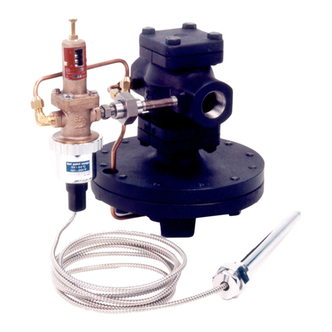
3. Loosen lock nut (16) on the temperature pilot and
turnthe adjusting screw (15) and align the needle
withthe required temperatureposition on thedial.
See Table 2-1. Note that the number on the dial
willgive anapproximate temperature valuewith
thecorrespondingtemperature range.
4. Loosen lock nut (28) on the pressure pilot and
turnadjusting screw (27)counterclockwise
removingall tensionfrom adjustingspring (24).
5. Openvalve onoutlet ofOB 2000PT and also on
controlpipe.
6. Openinlet valveto OB2000PT– SLOWLY.
7. Turnthe adjustingscrew (27) onpressure pilot
valve clockwise until the heater output is 5°F
abovethe desiredtemperature setting.If
temperature adjustment in step 3 limits this
operation,adjust temperature pilot adjusting
screwaccordingly. Make sureall valvesbetween
theOB 2000PT and equipment areopen and
equipment is calling for steam.
8. Turnadjusting screw(15) ontemperature pilot
counterclockwise,lowering to thedesired
temperature.
9. Allow system to stabilize and adjust temperature
accordingly.
10. Tightenlock nut (16)on the temperaturepilot and
lock nut (28) on pressure pilot.
11. If adjustments are made at partial load the
temperaturewill sagunder heavierloads. When
maximum load occurs increase pressure setting
enoughto maintaindesired temperature.
Note: Make sure the set pressure temperature does
not exceed the temperature limit of the capillary.
Capillarycan withstand amaximum of 68°Fabove the
ratedrange.
Example –Capillary range of 131-201°F will
withstandtemperature of 269°F.
E. Maintenance Inspection
1. TroubleshootingHints –many of the problems
thatoccur withpressure/temperature regulators
aredue to dirtholding the mainor pilot valveopen.
Additionally make sure that the thermometer
sensingthe fluid temperatureis operating
correctly.
2. Check that the bellows follower was installed.
Disassembly
Before disassembly, make sure the inlet and outlet valves
to the regulator are closed and the pressure has been
relieved.
A. Disassembly of Temperature Pilot Valve
(See Figure 4-1 on Page 4)
1. Loosencapillary ringunion (22)and temperature
sensor bellows (35). Make sure not to lose
bellowsfollower(10).
2. Loosen lock nut (16) and turn adjusting screw (15)
counterclockwise (left), freeingup adjusting
spring(14).
3. Removefour hexagonalbolts (17)from the spring
housing(2) andremove adjustingspring (14).
4. Removetop bellowsplate (6) andtop seal bellows
(5).
5. Loosenthe guide(7) and remove the bottom
bellows plate (8) and the bottom bellows seal (5)
fromthe bottom halfof temperature pilot.
6. Removepilot valve andstem (3).
7. Forassembly procedure,followreverse order.
B. Disassembly of Pressure Pilot Valve
(See Figure 5-1 on Page 5)
1. Loosen the lock nut (28) and the adjusting
screw(27) counterclockwise (left)and turn
until the pressure is relieved from set point
adjustingspring (24).
2. Removefour hexhead bolts and take out
adjustingspring (24), bottom spring plate (26), top
springplate (25), andtwo pilot diaphragms (23).
3. Removepilot valveassembly (17,18, 19, 20,21)
at the center of the pilot body (2).
4. Pilotbody canbe removedfrom main valve by
disconnectingfitting (30A)and removingfour hex
bolts(38). Careshould be taken when removing
pilotfrom mainvalve. The main valve isheld bya
spring which is compressed.
C. Disassembly of Main Valve
(See Figure 5-1 on page 5)
1. Disconnect the copper tubing on the side of the
valve(See Fittings 30A, 30B, 30C).
