CODE: OLSTRENPL01 | REV:4| DATE:05/2013
ENG
PL
S - OT - OR
INSTALLATION AND OPERATING INSTRUCTIONS
FOR PNEUMATIC VIBRATORS
INSTRUKCJE INSTALACJI I OBSŁUGI
WIBRATORÓW PNEUMATYCZNYCH
Część 0 – OPIS
- Wibratory pneumatyczne serii S-OT-OR zostały zaprojektowane i skonstruowane zgodnie z obowiązującymi normami:
- UNI EN 13463-1 - EN 13463-5 - ISO 14121 - UNI EN 1127-1
W zgodności z dyrektywami - 94/9/CE - 2006/42/CE
Ogólne właściwości wibratorów serii S-OT-OR zostały wymienione poniżej:
Temperatura działania:
S / OR od –20°C do + 200°C
OT od –20°C do + 120°C
Wibratory produkują wibracje wielokierunkowe. Są używane do utrzymywania stałego przepływu w lejach i silosach, jako napędy dla zsuwni lub sit na stołach wibracyjnych.
Generalnie służą do luzowania, przenoszenia i wybierania masowych substancji stałych oraz redukcji tarcia.
Są idealne do stosowania w przemyśle spożywczym, atmosferach wybuchowych, środowisku mokrym oraz na zewnątrz. Częstotliwość drgań i siła odśrodkowa zależą od
ciśnienia pracy.
S: Wibratory kulowe serii„S”składają się z anodyzowanego korpusu aluminiowego, wewnątrz którego w specjalnie utwardzonym na ścieranie stalowym gnieździe obraca się
hartowana stalowa kula.Wibratory S wytwarzają drgania o małych amplitudach.
OT: Wibratory turbinowe serii„OT”zbudowane są z anodyzowanego korpusu aluminiowego, wewnątrz którego obraca się niewyważona turbina.Wibracje są generowane są
przez turbinę ze zintegrowanymi ciężarami wirującymi, która obraca się na dwóch wysokoobrotowych łożyskach kulkowych.Wytrząsarki turbinowe OT wywołują wibracje o
wysokich częstotliwościach i siłach odśrodkowych. Wibracje objawiają się wysoką amplitudą nawet przy niskim ciśnieniu roboczym.
OR: Wibratory wałkowe serii„R”zbudowane są z anodyzowanego korpusu aluminiowego, wewnątrz którego znajdują się wałki z hartowanej stali oraz żeliwny pierścień nośny.
Wibracje są generowane przez wirnik wykonujący ruch mimośrodkowy wewnątrz stalowego pierścienia nośnego Wibratory wałkowe typu OR generują bardzo wysokie
częstotliwości i siły odśrodkowe przy niskim poborze mocy w porównaniu z podaną mocą.
Część 1 – NORMY OGÓLNE
Przed użyciem urządzenia należy dokładnie przeczytać instrukcje, a niniejszy podręcznik powinien być przechowywany w bezpiecznym miejscu dla dalszych konsultacji.
Symbol:
oznacza występowanie dużego niebezpieczeństwa, które, jeśli zostanie zignorowane, może poważnie zagrażać życiu i zdrowiu osób.
Przy dostawie produktu należy sprawdzić czy:
• Opakowanie nie nosi śladów zniszczenia w stopniu, który mógłby uszkodzić sam produkt.
• Nie ma uszkodzeń zewnętrznych produktu.
• Wyposażenie elektryczne odpowiada specykacji w zamówieniu; jakakolwiek niezgodność i/lub uszkodzenie zewnętrzne muszą zostać natychmiastowo zgłoszone
w sposób szczegółowy rmie spedycyjnej oraz producentowi i/lub dealerowi. .
Część 1.1 – IDENTYFIKACJA
Model wibratora i inne dane zostały wytłoczone na tabliczce znamionowej.
Dane te należy zawsze podawać przy zamawianiu części zamiennych lub interwencjach technicznych.
Część 1.2 – PRZEZNACZENIE UŻYCIA
UWAGA: Zabrania się uruchamiania wibratorów opisanych w niniejszym podręczniku, jeśli nie zostało potwierdzone, że urządzenie lub system, do którego zostały podłączone
spełniają wymogi zapisów Dyrektywy 2006/42/CE.
Wibratory pneumatyczne opisane w niniejszym Podręczniku zostały zaprojektowane i przetestowane do użytku w atmosferach potencjalnie wybuchowych
zaklasykowanych jako strefa 21 (pył) i strefa 1 (gaz) CAT II G D. Przed uruchomieniem, użytkownik musi upewnić się, że system, do którego został podłączony wibrator,
jest wprowadzony w stan bezpieczeństwa z punktu widzenia ryzyka eksplozji, oraz, że został przygotowany ”dokument dotyczący ochrony przed wybuchem”zgodnie z
założeniami Dyrektywy ATEX94/9CE.
Section 0 – DESCRIPTION
S-OT-OR vibrators are designed and constructed in accordance with the following applicable standards:
- UNI EN 13463-1 - EN 13463-5 - ISO 14121 - UNI EN 1127-1
Conformity to Directives – 94/9/CE
The general features of the S-OT-OR series are listed below:
Operating temperature:
S / OR from –20°C to + 200°C
OT from –20°C to + 120°C
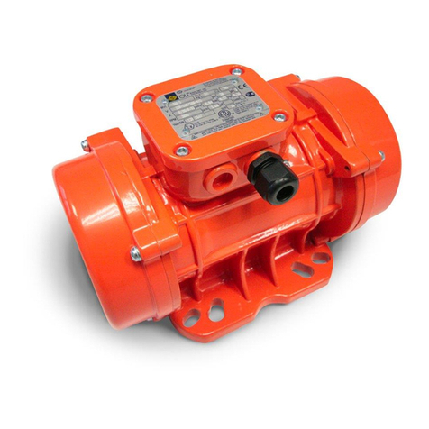
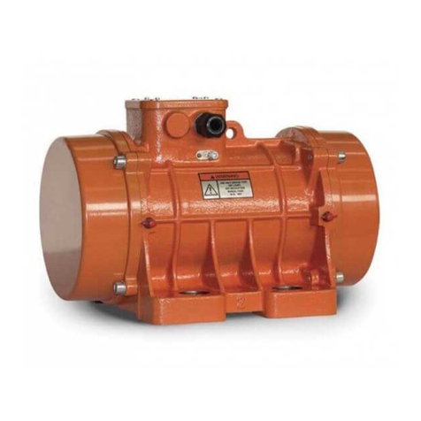
The vibrators produce multi-directional vibrations.They are used to keep a constant ow in hoppers and silo’s, to drive chutes and are also used in screens and
vibrating tables. Generally for loosening, conveying and separating of bulk materials and for the reduction of friction.
The vibrators are ideal for use in the food industry, explosive atmosphere’s, wet environment’s and outside. The frequency and the centrifugal force are
determined by the operating pressure.
S : Ball vibrators“S”consist of an anodized aluminium body inside which a tempered steel ball rotates on an anti-wear tempered steel seating. Vibrator“S”
generates vibrations of small amplitudes.
OT:Turbine vibrators“OT”consist of an anodized aluminium body inside which an unbalanced turbine rotates. Vibration is generated by a strongly unbalanced
turbine which rotates on two highspeed ball bearings. OT vibrators develop a high work moment and a high vibration frequency.Vibrations present a large
amplitude even with low operating pressure.
OR:The roller vibrators series“R”are formed by an anodized aluminium body inside which a hardened steel roller wheels an a cast iron race. Vibration is
generated by a rotor which describes an epicycloidal
movement inside a steel race. The OR vibrators generate a very high frequency with low consumption as compared to the force given.
Section 1 – GENERAL REGULATIONS
Read these instructions carefully before using the equipment,and keep the manual in a safe place for future reference.
Symbol: !It indicates situations of serious danger which, if ignored, can seriously put to a risk the health and safety of persons.
On receiving the product please check that:
• the packing is not damaged to such an extent as to have damaged the product.
• there is no external damage to the product.
• the electrical supply corresponds to the order specications; non compliance and/or external damage, if any, must be reported immediately in detail to
the forwarding agent and the manufacturer and/or dealer.
Section 1.1 – IDENTIFICATION
The vibrator’s type and other various data are embossed on the identication plate
This information must always be stated when requesting spare parts or a technical intervention.
Section 1.2 – USE OFTHE VIBRATOR
WARNING: It is forbidden to operate the motor-vibrators described in this manual unless the machine or plant in which these are incorporated is declared as
conforming to the provisions of Directive 2006/42/EC.
The pneumatic vibrators described in this Manual are designed and tested for use in potentially explosive areas classied as zone 21(dust) zona1 (gas) CAT II
2 G D. The user must make sure the plant in which the pneumatic vibrator is installed has been set in safety condition from the point of view of explosion risk
before being started up, and that the“document on protection against explosions”has also been prepared as specied by Directive ATEX 94/9/CE.
Zastosowanie wibratora do jakichkolwiek prac innych niż przewidziane i niezgodnych z opisanymi w niniejszej broszurze, a także uważanych za
nieprawidłowe i zabronione zwalnia producenta z jakiejkolwiek odpowiedzialności bezpośredniej oraz pośredniej.
Część 2 – GWARANCJA
Gwarancja na wady fabryczne jest ważna przez dwadzieścia cztery miesiące od daty zakupu (widocznej na dokumencie dostawy przekazywanym wraz z towarem).
Gwarancja obejmuje wszystkie części mechaniczne z wyłączeniem elementów ulegających zużyciu. Gwarancja traci ważność, wraz z równoczesnym zwolnieniem Producenta
z odpowiedzialności bezpośredniej lub pośredniej w następujących przypadkach:
Jeśli z produktem obchodzono się w sposób niewłaściwy lub był on używany nieprawidłowo, jeśli wykonane zostały naprawy lub modykacje przez nieupoważniony
personel, lub gdy zostały użyte nieoryginalne części zamienne.
Części zwrócone do naprawy w ramach gwarancji, są zwracane na koszt dostarczającego.
Część 3 – NORMY BEZPIECZEŃSTWA
Jeśli klient zachowuje ostrożność (odpowiednią dla tego rodzaju urządzenia), stosując się równocześnie do wskazówek zawartych w podręczniku“OBSŁUGA I KONSERWACJA”,
praca na urządzeniu jest bezpieczna. Procedury dotyczące prac stwarzających zagrożenie pożarowe (jak cięcie, spawanie…) oraz procedura (LOTO) oznakowania i
zabezpieczenia maszyny przed uruchomieniem (segregacja elektryczna i mechaniczna), muszą być przestrzegane.
Autoryzacja prac stwarzających zagrożenie pożarowe MUSI zostać wydana przez przeszkolony personel techniczny z uwzględnieniem ryzyka wybuchu pyłów.
Poziom hałasu urządzenia NIGDY nie przekracza 90 dB(A)*.
*Mierzony w normalnych warunkach pracy, zgodnie z normą UNI EN ISO 11202.W celu uniknięcia niepożądanej emisji dźwięku do środowiska, zalecamy używanie
wibratorów z zastosowaniem tłumika.
Część 3.1 – INSTALACJA
Zamocować urządzenie do czystej wypoziomowanej powierzchni za pomocą dwóch śrub mocujących ( rozmiar śruby i moment dokręcania – patrz tabela).
Użyć podkładek blokujących samohamownych (nie używać podkładek sprężystych).
By uniknąć poluzowania, użyć nakrętek samoblokujących. Zaleca się zastosowanie jako podbudowy prolu wzmacniającego (kształtownik U typu„B”lub płyty typu„A”).Ta
część wzmacniająca powinna zostać przyspawana do urządzenia.
Pozwala to na optymalne przeniesienie wibracji i chroni obiekt przed uszkodzeniem.
Rama, na której zostaje zamontowany wibrator pneumatyczny musi być uziemiona.
Wibrator należy zamocować do ramy za pomocą wkrętów i podkładek, By połączyć wibrator ekwipotencjalnie, należy użyć podkładki ząbkowana (UNI8842), która musi
zostać zamocowana w kontakcie z korpusem. Końcówkę kabla należy podłączyć do uziemionej instalacji.
Część 4 – UWAGI OPERACYJNE !
Sprężone powietrze dostarczane do różnorodnych urządzeń, musi posiadać specjalne właściwości:
1) Czyste: wolne od osadu, który mógłby zniszczyć zawory elektromagnetyczne obecne w wibratorze pneumatycznym.
2) Osuszone: wskazane jest użycie separatora kondensatu
3) Nasmarowane: Żywotność wibratora zostanie wydłużona przy odpowiednim smarowaniu.
Jakość powietrza wg ISO8573-1:2010, klasa 5.4.1 dla OT, klasa 5.4.4 dla S i OR.
UWAGA: przed podłączeniem sprężonego powietrza do wibratora pneumatycznego, należy opróżnić rury.
Opór powietrza wzrasta wraz z długością rury. Dla rur o długości do 3m dla sekcji wymienionych w tabelo zaleca się stosowanie minimalnych długości. Dla dłuższych rur,
zaleca się stosowanie większych przekrojów rur.
W przypadku rozładowania powietrza wyrzucanego przy pełnym obciążeniu wibratora, rura rozładowująca musi posiadać większą średnicę nominalną niż rura zasilająca.
Wlot powietrza posiada mniejszy otwór niż jego wylot. Zarówno wlot jak i wylot zostały oznaczone na przedzie za pomocą strzałek.
Podłączenie zasilania sprężonym powietrzem musi być dokładnie zamocowane. Mieszanie się powietrza wlotowego z wylotowym powoduje straty wydajności.
Zaleca się stosowanie orurowania i akcesoriów odpowiednich dla temperatur działania.
Zamocować elastyczne węże do sprężonego powietrza i zapewnić odpowiednie zabezpieczenia przeciwko rozłączeniu sekcji rur. Upewnić się, że ciśnienie w systemie zasilania
powietrzem jest zgodne z wartością zużycia powietrza podaną w instrukcji działania.W innym wypadku wibrator nie będzie działał zgodnie ze specykacją techniczną.
Wymagane jest zasilanie sprężonym powietrzem lub azotem o ciśnieniu od 2 do 6 bar (30 do 90 PSI).
Część 5 – KONSERWACJA
Wibratory S i OR nie wymagają konserwacji. Zewnętrzna część może być czyszczona za pomocą wilgotnej ścierki. Nie kierować strumienia wody pod ciśnieniem bezpośrednio
na wibrator. Po takim czyszczeniu należy włączyć urządzenie na krótką chwilę. W modelu OT należy co 3000 godzin pracy wymieniać łożyska kulkowe.
Część 6 – CZĘŚCI ZAMIENNE
Zobacz tabela.
Część 7 – RYZYKA REZYDUALNE
Jakiekolwiek czynności konserwacyjne na zewnątrz wibratora pneumatycznego MUSZĄ być wykonywane przy wyłączonej maszynie i po upewnieniu się,
że w powietrzu nie unosi się pył.
Ryzyka mechaniczne.
W trakcie czynności, operator musi zawsze stosować środki ochrony osobistej.
Obecność potencjalnie szkodliwych pyłów
W przypadku standardowych jak i nadzwyczajnych czynności konserwacyjnych, operator jest zobowiązany do stosowania odpowiednich środków ochrony osobistej, a w
szczególności maski chroniącej drogi oddechowe o klasie odpowiedniej dla przetwarzanego pyłu, jak również rękawice i odzież ochronną. Więcej informacji można znaleźć w
karcie bezpieczeństwa produktu przetwarzanego przez urządzenie.
Obecność szkodliwych pyłów
Jeśli operator musi wykonywać pracę w obecności szkodliwych substancji przy obsłudze materiałów pylistych, w przypadku standardowych jak i nadzwyczajnych działań,
jest zobowiązany do stosowania odpowiednich środków ochrony, zgodnie z zaleceniami w karcie bezpieczeństwa produktu przetwarzanego przez zakład, w którym został
zainstalowany wibrator.
Ryzyko związane z obwodami pod ciśnieniem (hydraulicznym, pneumatycznym)
Podczas działań konserwacyjnych i/lub naprawczych, należy uwolnić ciśnienie z instalacji i akumulatorów.
Część 8 – ROZWIĄZYWANIE PROBLEMÓW
Patrz tabela.
Its use for jobs dierent from those envisioned and non-conform to that described in this booklet, as well as being considered improper and
prohibited, releases the Manufacturer from any direct and/or indirect liability.
Section 2 – GUARANTEE
The warranty is valid for manufacturing defects for a period of 24(twenty-four) months from the date of purchase (attested by the delivery note accompanying
the goods).
The warranty covers all the mechanical parts and excludes electrical parts and those subject to wear.The warranty will be invalidated, thus freeing the
Manufacturer of any direct or indirect responsibility in the following cases: if the product is
mishandled or used improperly, if repairs or modications are made by unauthorised personnel, or if non-original spare partsare used.
The material sent for repair under the warranty are returned CARRIAGE PAID.
Section 3 – SAFETY STANDARDS
lf the customer observes the normal caution (typical of this kind of equipment) together with the indications contained in this manual, work is safe.
Cutting and welding procedures must be carried out by qualied personnel. Suitable Hot-Works, (like cutting,welding…) and LOTO –lockout/tagout: procedure
for disconnecting the machine (electrical and mechanical segregation), must be applied for safe installation of the electric vibrator. Authorization for Hot works
MUST begiven by specialist trained personnel familiar with the risk of explosion of powders
The noise level of the vibrators measured is never greater than 90 dB(A)*
*Measured in normal operating conditions in accordance with standard UNI EN ISO 11202.
We recommend in order to avoid unnecessary noise for the environment, the vibrators should not be operated without a silencer.
Sezione 3.1 – INSTALLATION !
The unit must be fastened to a clean and level surface with two fastening screws (for screw size and tightening torque see table).
Use self-locking screw retention washers (no spring washers).
Use self-locking nuts against loosening. It is highly recommended to use a reinforcement section (U-section type“B”or plate type“A”) as substructure. This
reinforcement section should be welded to the object.
This allows optimal transfer of the vibration energy and saves any direct damage to the object.
The frame on which the pneumatic vibrator is mounted must be in equipotential.
The vibrator must be xed to the frame by means of bolts and washers. For connecting the vibrator in equipotential use the toothed washer (UNI8842) that
must be tted in contact with the body. The wire terminal must be connected to an earth wire.
Section 4 – OPERATIVE NOTES
The compressed air supplied to the various utilities must have certain special features:
1) clean: free of scale which could damage the solenoid valves present on the pneumatic actuator.
2) dehumidied: use of a condensate trap is advisable.
3) lubricated:Only S and OR type need lubrication.The life time of the vibrator will be extended with lubrication.
Air supply quality following ISO8573-1:2010 class 5.4.1 for OT, class 5.4.4 for S e OR.
Attention: before connecting the compressed air to the pneumatic actuator utilities, empty the pipes.
The air resistance increases with the length of the pipe. For pipe lengths of up to 3m then the minimum length is required for the following cross section.
For longer supply lines it is recommended to use bigger cross sections.
If the air owing out is discharged and the vibrator is at full power, the discharge pipe must have a bigger nominal width than the supply pipe. The air inlet has
a smaller opening than the air outlet. Both are marked on the front side by arrows.
The pressurized air infeed must be xed safely. Mixing up air inlet and air outlet leads to loss in performance.
Please use pipes and accessories suitable for the operating temperatures. Fix exible compressed air hose pipes and provide necessary precautions against
unwanted detachment of a pipe section. Make sure that the pressure in the air system is able to meet the air consumption value specied in the operating
instructions. Otherwise the vibrator will not be able to work according to the technical specications. Compressed air or nitrogen of 2 to 6 bar (30 to 90 PSI) is
required.
Section 5 – MAINTENANCE
S, OT and OR vibrators are maintenance-free. From outside they can be cleaned with a damp cloth. Operate the vibrator for a short while after.
Do not direct high pressure water jets on the vibrator.
Section 6 – SPARE PARTS
For spare parts please refer to table.
Section 7 – RESIDUAL RISKS
All maintenance operations on the outside of the pneumatic hammer MUST BE done with the plant stopped and in the absence of airborne dust.
Mechanical risk
For maintenance operations, it is compulsory for the operator to always use personal protection equipment.
Presence of potentially hazardous dusts
In the event of both routine and extraordinary maintenance, the operator must wear suitable personal protection equipment, and in particular, use a safety
mask for the respiratory tract depending on the type of dust daalt as well as gloves and clothing.
For more details, refer to the safety chart of the product handled.
Presence of harmful dusts
If the operator is required to work in the presence of harmful substance while handling the powders, for carrying out routine and special operations, he must
use suitable protective equipment as indicated in the safety chart of the product handled by the appliance in which the electric vibrator is inserted.
Hazards deriving from pressurized circuits (hydraulic, pneumatic)
During mainten- ance and/or repair operations pressure must be discharged from the plants and accumulators.
Section 8 –TROUBLESHOOTING CHART
Refer to table.
S - OR
T amb. II 2D c Tx II 2G c Tx
°C Tx (°C) Tx
≥ -20 ≤ 90 95 T5
≥ -20 ≤ 130 135 T4
≥ -20 ≤ 195 200 T3
≥ -20 ≤ 200 210 T2
OT
T amb. II 2D c Tx II 2G c Tx
°C Tx (°C) Tx
≥ -20 ≤ 90 95 T5
≥ -20 ≤ 120 125 T4
S - OR
T pom. II 2D c Tx II 2G c Tx
°C Tx (°C) Tx
≥ -20 ≤ 90 95 T5
≥ -20 ≤ 130 135 T4
≥ -20 ≤ 195 200 T3
≥ -20 ≤ 200 210 T2
OT
T pom. II 2D c Tx II 2G c Tx
°C Tx (°C) Tx
≥ -20 ≤ 90 95 T5
≥ -20 ≤ 120 125 T4
Rights reserved to modify technical specications
Dane techniczne mogą ulegać zmianom
