1
SLOU500–December 2017
Submit Documentation Feedback Copyright © 2017, Texas Instruments Incorporated
TAS2770YFF Evaluation Module
User's Guide
SLOU500–December 2017
TAS2770YFF Evaluation Module
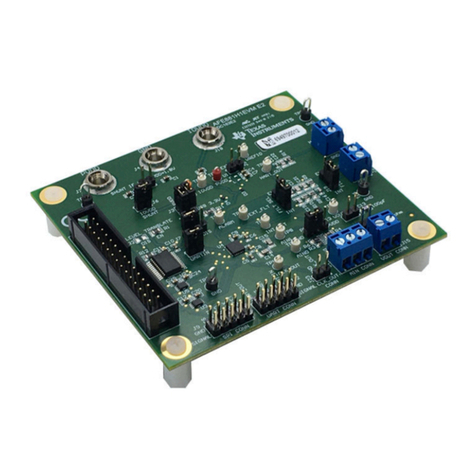
This user’s guide describes the characteristics, operation, and use of the TAS2770YFF-EVM Reference
Board. A complete schematic diagram, printed-circuit board layouts, and bill of materials are included in
this document.
Contents
1 Export Control Notice........................................................................................................ 2
3 Description.................................................................................................................... 2
4 Specifications................................................................................................................. 2
5 Software....................................................................................................................... 2
6 Mono Setup................................................................................................................... 3
7 Multi-Channel Setup......................................................................................................... 6
8 Digital Audio Interfaces ..................................................................................................... 7
8.1 Digital Audio Interface Selection.................................................................................. 8
9 Hardware Documentation ................................................................................................. 10
9.1 TAS2770YFF-EVM Schematics................................................................................. 10
9.2 TAS2770YFF Reference Board Printed Circuit Board Layout .............................................. 15
9.3 TAS2770YFF Evaluation Board Bill of Materials.............................................................. 23
List of Figures
1 TAS2770YFF-REF1 Stereo Configuration ............................................................................... 3
2 Playback Device Settings................................................................................................... 4
3 Texas Instruments Audio Control Panel.................................................................................. 4
4 Multi-Channel Setup......................................................................................................... 6
5 USB Audio Input Configuration ............................................................................................ 8
6 AP or PSIA Input Configuration............................................................................................ 9
7 Schematic: XMOS USB Controller....................................................................................... 10
8 Schematic: Input Multiplexing and Level Shift.......................................................................... 11
9 Schematic: External Input and Output Routing ........................................................................ 12
10 Schematic: TAS2770YFF Channel 1 Control........................................................................... 13
11 Schematic: Onboard Power............................................................................................... 14
12 PCB: Top Silkscreen....................................................................................................... 15
13 PCB: Top Solder Mask.................................................................................................... 16
14 PCB: Top Copper .......................................................................................................... 17
15 PCB: Copper Layer 2...................................................................................................... 18
16 PCB: Copper Layer 3...................................................................................................... 19
17 PCB: Bottom Copper ...................................................................................................... 20
18 PCB: Bottom Solder Mask ................................................................................................ 21
19 PCB: Bottom Silk Screen.................................................................................................. 22
List of Tables
1 Reference Board Specifications ........................................................................................... 2
2 Default Jumper Settings .................................................................................................... 5
3 TAS2770YFFEVM Bill of Materials ...................................................................................... 23
