Arris DCX525 User manual

INSTALLATION MANUAL
DCX525
All Digital High-Definition Set-top

©ARRIS Enterprises, Inc. 2015 All rights reserved. No part of this publication may be reproduced in any form or by any means
or used to make any derivative work (such as translation, transformation, or adaptation) without written permission from
ARRIS Enterprises, Inc. (“ARRIS”). ARRIS reserves the right to revise this publication and to make changes in content from time
to time without obligation on the part of ARRIS to provide notification of such revision or change. ARRIS and the ARRIS logo
are all trademarks of ARRIS Enterprises, Inc. MoCA is a registered trademark of Multimedia over Coax Alliance. HDMI is a
trademark of HDMI Licensing LLC. Manufactured under license from Dolby Laboratories. Dolby, Pro Logic, and the double-D
symbol are trademarks of Dolby Laboratories. This product incorporates copy protection technology that is protected by U.S.
patents and other intellectual property rights. Use of this copy protection technology must be authorized by Rovi Corporation,
and is intended for home and other limited viewing uses only unless otherwise authorized by Rovi Corporation. Reverse
engineering or disassembly is prohibited. Other trademarks and trade names may be used in this document to refer to either
the entities claiming the marks and the names of their products. ARRIS disclaims proprietary interest in the marks and names
of others.
ARRIS provides this guide without warranty of any kind, implied or expressed, including, but not limited to, the implied
warranties of merchantability and fitness for a particular purpose. ARRIS may make improvements or changes in the
product(s) described in this manual at any time.
The capabilities, system requirements and/or compatibility with third-party products described herein are subject to change
without notice.

Safety and Regulatory Information
Safety and Regulatory
Information
IMPORTANT SAFETY INSTRUCTIONS
•Read these instructions.
•Keep these instructions.
•Heed all warnings.
•Follow all instructions.
•Do not use this apparatus near water.
•Clean only with dry cloth.
•Do not block any ventilation openings. Install in accordance with the manufacturer’s instructions.
•Do not install near any heat sources such as radiators, heat registers, stoves, or other apparatus (including amplifiers)
that produce heat.
•Do not defeat the safety purpose of the polarized or grounding type plug. A polarized plug has two blades with one
wider than the other. A grounding type plug has two blades and a third grounding prong. The wide blade or the third
prong is provided for your safety. If the provided plug does not fit into your outlet, consult an electrician for
replacement of the obsolete outlet.
•Protect the power cord from being walked on or pinched particularly at plugs, convenience receptacles, and the
point where they exit from the apparatus.
•Only use attachments/accessories specified by the manufacturer.
•Unplug this apparatus during lightning storms or when unused for long periods of time.
•Refer all servicing to qualified service personnel. Servicing is required when the apparatus has been damaged in any
way, such as the power supply cord or plug is damaged, liquid has been spilled or objects have fallen into the
apparatus, the apparatus has been exposed to rain or moisture, does not operate normally, or has been dropped.
Important Safety Considerations
The mains plug is the main disconnect device. It shall remain readily accessible and operable.
The apparatus shall not be exposed to dripping or splashing and no object filled with liquids, such as vases, shall be placed on the
apparatus.
During Transportation to the Subscriber Home
Transport the cable terminal in its shipping box or an equally padded container.
Do not expose the terminal to rain or moisture.
i
All Digital High-Definition Set-top DCX525 •Installation Manual i
© ARRIS Enterprises, Inc. 2015 All rights reserved. 365-095-25870 x.2

Safety and Regulatory Information
During Installation
•Do not place the cable terminal in an enclosed area where the cooling vents are blocked or impede the flow of air
through the ventilation openings.
•Install the terminal so that its position does not interfere with its proper ventilation. For example, do not place the
terminal on a bed, sofa, rug, or similar surface that could block the ventilation openings.
•Install the terminal away from heat sources such as radiators, heat registers, and stoves. Installation of the terminal
near consumer electronics devices, such as stereo receiver/amplifiers and televisions, is permitted as long as the air
surrounding the terminal does not exceed 40º C (104º F).
•Place the terminal on a flat surface not prone to vibration or impact.
•Do not install the terminal in an area where condensation occurs.
•To prevent the temporary loss of guide data and cause a temporarily non-responding terminal, do not plug the AC
power cord into a switched power outlet.
FCC Compliance
Note: This equipment has been tested and found to comply with the limits for a Class B digital device, pursuant to part 15 of the
FCC Rules. These limits are designed to provide reasonable protection against harmful interference in a residential installation. This
equipment generates, uses, and can radiate radio frequency energy and, if not installed and used in accordance with the
instructions, may cause harmful interference to radio communications. However, there is no guarantee that interference will not
occur in a particular installation. If this equipment does cause harmful interference to radio or television reception, which can be
determined by turning the equipment off and on, the user is encouraged to try to correct the interference by one or more of the
following measures:
•Reorient or relocate the receiving antenna.
•Increase the separation between the equipment and receiver.
•Connect the equipment into an outlet on a circuit different from that to which the receiver is connected.
•Consult the dealer or an experienced radio/TV technician for help.
Caution: Changes or modifications not expressly approved by ARRIS for compliance could void the user’s authority to operate the
equipment.
This device complies with part 15 of the FCC Rules. Operation is subject to the following two conditions: (1) This device may not cause
harmful interference, and (2) this device must accept any interference received, including interference that may cause undesired
operation.
All Digital High-Definition Set-top DCX525 •Installation Manual ii
© ARRIS Enterprises, Inc. 2015 All rights reserved. 365-095-25870 x.2

Safety and Regulatory Information
FCC Declaration of Conformity
ARRIS Enterprises, Inc. 3871 Lakefield Drive, Suwanee, GA 30024, 1-215-323-1000, declares that the DCX525 receiver complies with
47 CFR Parts 2 and 15 of the FCC rules as a Class B digital device.
Industry Canada (IC)
This Class B digital device complies with Canadian ICES-003.
Cet appareil numérique de la classe B est conforme à la norme NMB-003 du Canada.
Special Symbols That Might Appear on the Equipment
The exclamation point, within an equilateral triangle, is intended to alert the user to the
presence of important installation, servicing, and operating instructions in the documents
accompanying the equipment.
This symbol indicates that dangerous voltage levels are present within the equipment. These
voltages are not insulated and may be of sufficient strength to cause serious bodily injury when
touched. The symbol may also appear on schematics.
Caring for the Environment by Recycling
When you see this symbol on an ARRIS product, do not dispose of the product with residential or
commercial waste.
Recycling your ARRIS Equipment
Please do not dispose of this product with your residential or commercial waste. Some countries or
regions, such as the European Union, have set up systems to collect and recycle electrical and
electronic waste items. Contact your local authorities for information about practices established for
your region.
All Digital High-Definition Set-top DCX525 •Installation Manual iii
© ARRIS Enterprises, Inc. 2015 All rights reserved. 365-095-25870 x.2

Contents
Contents
Safety and Regulatory Information
................................................................................................................ i
Tables
............................................................................................................................................................ v
Figures
.......................................................................................................................................................... vi
Introduction
.................................................................................................................................................. 1
Features ...............................................................................................................................................................................2
Tuners ...........................................................................................................................................................................2
Standard Audio/Video Features..............................................................................................................................2
Standard Data Features............................................................................................................................................2
Standard Miscellaneous Features..........................................................................................................................2
Getting Help ........................................................................................................................................................................2
Overview
....................................................................................................................................................... 4
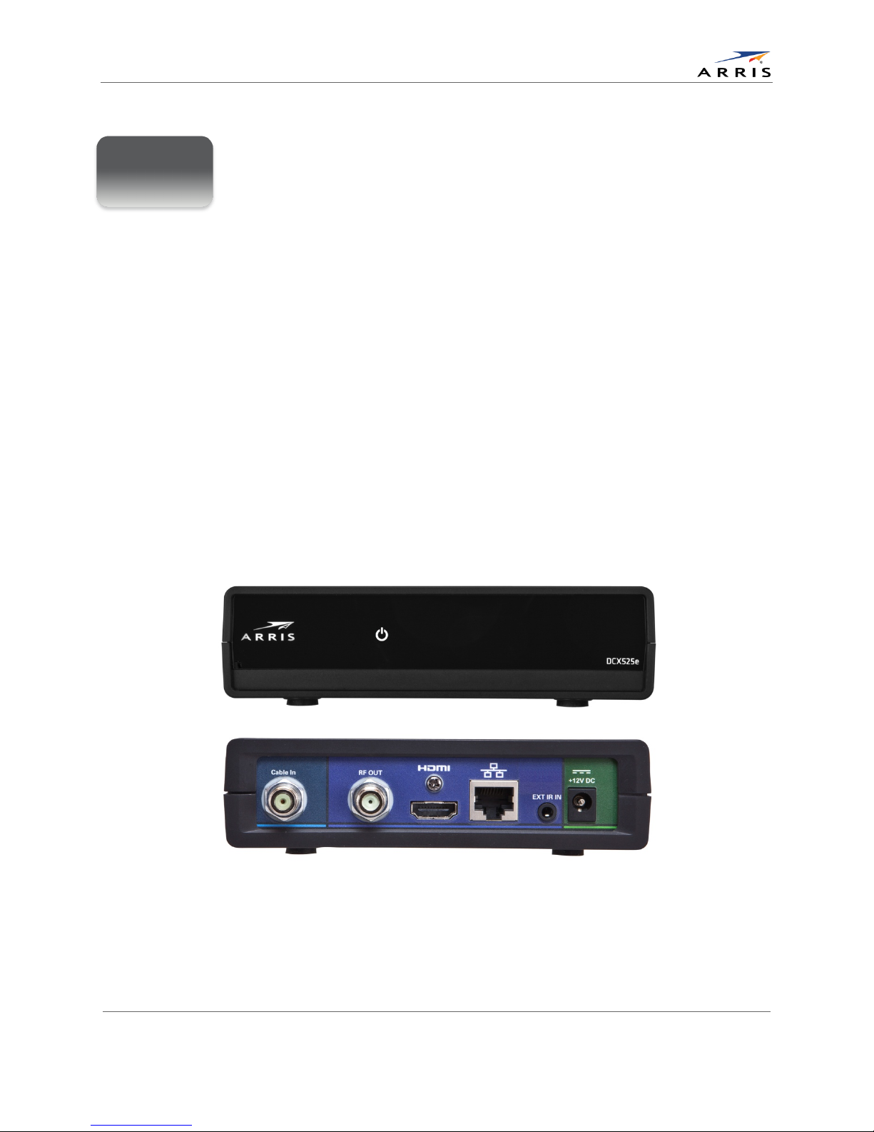
Rear Panel............................................................................................................................................................................4
Installation
..................................................................................................................................................... 5
Before You Begin ...............................................................................................................................................................5
Cold Reset Procedure.......................................................................................................................................................5
Cold Reset Method ....................................................................................................................................................6
Video Connection Options...............................................................................................................................................7
Audio Connection Options ..............................................................................................................................................8
Installation Overview.........................................................................................................................................................9
CableIn Connection...........................................................................................................................................................9
Connecting an HDTV — Single Connection for Video/Audio.................................................................................10
HDMI ...........................................................................................................................................................................10
Connecting an SDTV — Single Connection for Video/Audio..................................................................................11
Connecting an SDTV and VCR/DVD Recorder...........................................................................................................12
Connecting an A/V Receiver, SDTV and VCR/DVD Recorder..................................................................................13
Operational Check for the Remote Control...............................................................................................................15
Configuring the User Settings
..................................................................................................................... 16
Getting Started .................................................................................................................................................................16
Configuring the User Settings Menu Screen .............................................................................................................16
Native Mode Settings Screen........................................................................................................................................22
Additional HDMI Settings Screen .................................................................................................................................25
Additional Closed Caption Settings Screen ...............................................................................................................27
Subtitle and DVS Settings Screen ................................................................................................................................29
All Digital High-Definition Set-top DCX525 •Installation Manual iv
© ARRIS Enterprises, Inc. 2015 All rights reserved. 365-095-25870 x.2

Tables
Advanced Audio/Video Settings Screen .....................................................................................................................31
Graphics Overlaying the Video .....................................................................................................................................32
Diagnostics
.................................................................................................................................................. 33
Using the Diagnostics .....................................................................................................................................................33
General Status ..........................................................................................................................................................34
Purchase Status........................................................................................................................................................36
Out-Of-Band (OOB) Status .....................................................................................................................................37
Agile OOB Tuner Hunting .......................................................................................................................................39
DOCSIS Set-top Gateway ........................................................................................................................................40
In-Band Status...........................................................................................................................................................43
Unit Address ..............................................................................................................................................................45
Current Channel Status ..........................................................................................................................................47
RF Modem (Upstream .............................................................................................................................................50
Code Modules...........................................................................................................................................................52
Memory Configuration ............................................................................................................................................54
Audio/Video Status ..................................................................................................................................................55
Interface Status.........................................................................................................................................................59
User Setting Status ..................................................................................................................................................61
DOCSIS Status ...........................................................................................................................................................62
Application Specific Information ...........................................................................................................................65
Interactive Status......................................................................................................................................................66
Connected Home .....................................................................................................................................................68
Troubleshooting
.......................................................................................................................................... 70
Tables
Table 1: Video Output Options .......................................................................................................................................7
Table 2: Audio Output Options.......................................................................................................................................8
Table 3: User Settings Menu Field Descriptions.......................................................................................................19
Table 4: Native Mode Settings Field Definitions .......................................................................................................23
Table 5: Additional HDMI Settings Field Definitions.................................................................................................25
Table 6: Additional Closed Caption Settings Field Definitions...............................................................................28
Table 7: Subtitle and DVS Settings Field Definitions................................................................................................30
Table 8: Advanced Audio/Video Settings Field Definitions.....................................................................................32
Table 9: General Status Diagnostic Field Descriptions............................................................................................35
Table 10: Purchase Status Diagnostic Field Descriptions.......................................................................................36
All Digital High-Definition Set-top DCX525 •Installation Manual v
© ARRIS Enterprises, Inc. 2015 All rights reserved. 365-095-25870 x.2

Figures
Table 11: OOB Diagnostic Field Descriptions............................................................................................................38
Table 12: DSG Diagnostic Field Descriptions.............................................................................................................40
Table 13: In-Band Status Diagnostic Field Descriptions .........................................................................................43
Table 14: Unit Address Diagnostic Field Descriptions.............................................................................................45
Table 15: Current Channel Status Diagnostic Field Descriptions .........................................................................48
Table 16: RF Upstream Modem Diagnostic Field Descriptions.............................................................................51
Table 17: Code Modules Diagnostic Field Descriptions..........................................................................................52
Table 18: Memory Configuration Diagnostic Field Descriptions...........................................................................54
Table 19: Audio/Video Status Diagnostic Field Descriptions .................................................................................55
Table 20: Interface Status Diagnostic Field Descriptions .......................................................................................59
Table 21: DOCSIS Status Diagnostic Field Descriptions..........................................................................................62
Table 22: Application Specific Information Diagnostic Field Descriptions..........................................................65
Table 23: Interactive Status Diagnostic Field Descriptions ....................................................................................66
Table 24: Connected Home Diagnostic Field Descriptions....................................................................................69
Figures
Figure 1: Front and Rear Views.......................................................................................................................................1
Figure 2: Rear Panel ..........................................................................................................................................................4
Figure 3: Connecting an HDTV — Single Connection for Video/Audio................................................................10
Figure 4: Connecting an SDTV — Single Connection for Video/Audio ................................................................11
Figure 5: Connecting an SDTV and VCR/DVD Recorder..........................................................................................12
Figure 6: Connecting an A/V Receiver, SDTV, and VCR/DVD Recorder................................................................14
Figure 7: User Settings Menu—No HDMI Connection............................................................................................17
Figure 8: Default User Settings Menu When an HDMI Connection is in Place..................................................17
Figure 9: User Settings Menu—Available Options Illustrated ...............................................................................18
Figure 10: Native Mode Settings menu screen.........................................................................................................22
Figure 11: Additional HDMI Settings screen..............................................................................................................25
Figure 12: Additional Closed Caption Settings menu screen ................................................................................27
Figure 13: Subtitle and DVS Settings Menu Screen .................................................................................................29
Figure 14: Advanced Audio/Video Settings Menu Screen ......................................................................................31
Figure 15: Diagnostic Main Menu Screen ..................................................................................................................34
Figure 16: General Status Diagnostic Screen............................................................................................................34
Figure 17: Purchase Status Diagnostic Screen .........................................................................................................36
Figure 18: OOB Status Diagnostic Screen..................................................................................................................37
Figure 19: DSG Status Diagnostic Screen...................................................................................................................40
All Digital High-Definition Set-top DCX525 •Installation Manual vi
© ARRIS Enterprises, Inc. 2015 All rights reserved. 365-095-25870 x.2

Figures
Figure 20: In-Band Status Diagnostic Screens ..........................................................................................................43
Figure 21: Unit Address Diagnostic Screen ...............................................................................................................45
Figure 22: Current Channel Status Diagnostic Screens..........................................................................................47
Figure 23: RF Upstream Modem Diagnostic Screen................................................................................................50
Figure 24: Code Modules Diagnostic Screen.............................................................................................................52
Figure 25: Memory Configuration Diagnostic Screen..............................................................................................54
Figure 26: Audio/Video Status Diagnostic Screen ....................................................................................................55
Figure 27: Interface Status Diagnostic Screens ........................................................................................................59
Figure 28: User Setting Status Diagnostic Screen....................................................................................................61
Figure 29: DOCSIS Status Diagnostic Screens...........................................................................................................62
Figure 30: Application Specific Information Diagnostic Screen.............................................................................65
Figure 31: Interactive Status Diagnostic Screen .......................................................................................................66
Figure 32: Connected Home Diagnostic Screens.....................................................................................................68
All Digital High-Definition Set-top DCX525 •Installation Manual vii
© ARRIS Enterprises, Inc. 2015 All rights reserved. 365-095-25870 x.2

Introduction
Introduction
This manual provides instructions for cable operator personnel to install the ARRIS DCX525 All-
Digital High-Definition Cable Set-top. This unit includes a high-end processor, expanded
memory, and enhanced graphics to support digital and on-demand broadcast and interactive
services. It provides a full complement of interconnection options.
The DCX525 provides advanced capabilities, including:
•Authorization and purchase of on-demand programming
•HDTV output through a High-Definition Multimedia Interface (HDMI™)
•Surround-sound audio
•Ethernet port for future home networking applications
•Adaptability to various software platforms
As with all ARRIS digital cable set-tops, the hardware features are enabled by core operating and
third-party application software.
Figure 1: Front and Rear Views
1
All Digital High-Definition Set-top DCX525 •Installation Manual 1
© ARRIS Enterprises, Inc. 2015 All rights reserved. 365-095-25870 x.2

Introduction
Features
Tuners
•Single 1GHz digital video tuner (QAM 64/256)
•MPEG 2 Main Profile @ High Level (High-Definition)
•MPEG-4 H.264 (AVC) High-Definition decode
•One dedicated tuner for the out-of-band (OOB) control channel
Standard Audio/Video Features
•Embedded MediaCipher™ Conditional Access
•Compatible with ARRIS DCT/DCH legacy software API set
•Dolby® Digital, Dolby® Digital Plus, AAC-LC / HE-AAC, MP3
•High-definition (HDTV) decode of MPEG-2, MPEG-4 AVC (H.264)
•SCTE 55-1 Out-of-band
•Video scaling
•Video-in-Graphics
•Accelerated 2-D and 3-D graphics
•256 MB Flash, 512 MB DRAM
•Front panel Power/Standby LED
•Remote and on-screen diagnostics
•Switched Digital Video capable
•Rovi®, HDCP, DTCP, and CGMS-A content protection schemes on the respective interfaces
Standard Data Features
•10/100 Mbps Ethernet Port (RJ 45) on the rear panel
•External Infrared Receiver Input
Standard Miscellaneous Features
•Messaging capabilities
•Digital diagnostics
Getting Help
Help with your product is available online and by phone.
All Digital High-Definition Set-top DCX525 •Installation Manual 2
© ARRIS Enterprises, Inc. 2015 All rights reserved. 365-095-25870 x.2

Introduction
Find technical documentation in the CustomerCare 360 Documentation Center
(http://www.arrisi.com/cc360).
Get release updates and download software from DigitalCM (digitalcm.arrisi.com).
The ARRIS Training Learning Portal provides self-paced product training and course descriptions
of instructor-led training classes at http://www.arris.com/support/training. In many cases training
can be given at your location.
The Technical Assistance Center (TAC) provides assistance 24 hours a day, 7 days a week. To
open a case, use one of these contact methods:
•Customers in North American should call the TAC at 888-944-HELP (888-944-4357).
•Customers outside North America should call the TAC at IDD (International Direct Dialing
Number) + 1 + 215-323-2345.
•For Spanish language support, call 215-323-2346.
•Contact the TAC by e-mail at Tac.Helpdesk@arrisi.com
All Digital High-Definition Set-top DCX525 •Installation Manual 3
© ARRIS Enterprises, Inc. 2015 All rights reserved. 365-095-25870 x.2

Overview
Overview
Rear Panel
The rear panel contains connectors for video, audio, and RF cabling; data output; and modem
and data interface connectors. Some connectors are not enabled and require the support of
application software.
Figure 2: Rear Panel
1
Cable In — Connects to cable signal from the service provider
2
RF Out — Ch 3/4 modulated audio/video (SDTV) to TV or VCR
3
HDMI™ — High-Definition TV (HDTV) connector (Provides Dolby® Digital Plus (7.1) audio, Dolby®
Digital 5.1 audio or PCM output, volume controlled)
4
Ethernet* — Network connection
5
Ext IR Input — Connects to a remote control receiver accessory cable
6
Power connector
* Availability of certain features is dependent upon application support.
2
All Digital High-Definition Set-top DCX525 •Installation Manual 4
© ARRIS Enterprises, Inc. 2015 All rights reserved. 365-095-25870 x.2

Installation
Installation
Before You Begin
Before you move or change components on the subscriber’s entertainment system:
•Review the installation instructions.
•Determine if you are connecting to a standard analog NTSC TV (supporting an RF input), a
composite (baseband) video input, or a High-Definition TV (supporting component video
input or HDMI™ input).
•Determine if the subscriber has other equipment to be connected to the terminal (home
theater or A/V receiver, VCR, etc.).
•Verify that you have the necessary cables and other required items.
Cold Reset Procedure
This section describes the Cold Reset procedure for the ARRIS DCX525 set-top. The cold reset is
generally used by operational and field personnel to accomplish the following:
•Restore the set-top to a known state.
•Clear channel maps and application settings.
•Remove application and software objects above the platform code.
•Clear the Out of Band (OOB) Last Known Carrier (LKC) and force the units to hunt for a new
OOB control channel.
3
All Digital High-Definition Set-top DCX525 •Installation Manual 5
© ARRIS Enterprises, Inc. 2015 All rights reserved. 365-095-25870 x.2

Installation
Cold Reset Method
1. Remove the set-top from its packaging.
2. Plug in a serial connector to the DCX525 and open a terminal window.
3. AC power cycle the set-top.
4. Once the front panel indicator is illuminated after power has been applied to the DCX525,
quickly press and release the <Select> button on the remote.
If the <Select> key is properly detected, the optional terminal window indicates that the
<Select> key was received.
5. Press the following sequence of numbers on the remote control: 3, 2, and 8.
As each number in the sequence is pressed, the terminal window echoes back each button
press as D, C, and T for each number in the sequence.
The set-top now cold resets.
Note: The <Select> key is labeled <OK> on some remotes.
All Digital High-Definition Set-top DCX525 •Installation Manual 6
© ARRIS Enterprises, Inc. 2015 All rights reserved. 365-095-25870 x.2

Installation
Video Connection Options
Use the following guidelines to determine the best video connection for the subscriber’s home
entertainment system. To determine the available video inputs on the TV, check the manual
supplied with the TV or the TV itself.
Table 1: Video Output Options
Connector
TV Type
Description
HDMI™
HDTV and
SDTV
HDMI provides the highest-quality digital HD video signals. If the TV has
an HDMI or a DVI input, use the HDMI Output.
HDMI is a video and audio connection. If you use HDMI, no separate
audio connection to the TV is required.
RF OUT (coax)
SDTV
Use the RF OUT (coax) connector for SDTV.
The RF OUT (coax) connection is a video and audio connection. If you
use the RF OUT, no separate audio connection to the TV is required.
All Digital High-Definition Set-top DCX525 •Installation Manual 7
© ARRIS Enterprises, Inc. 2015 All rights reserved. 365-095-25870 x.2

Installation
Audio Connection Options
When connecting to a home theater receiver, depending on its inputs, you can use the following
DCX525 audio outputs:
Table 2: Audio Output Options
Connector
Description
HDMI
Unlike a DVI connection, an HDMI connection is capable of carrying digital video and
audio signals to the TV or a home theater receiver equipped with HDMI switching
support.
The HDMI connection can deliver Dolby Digital Plus, Dolby Digital, Linear PCM, and
other digital audio formats to a compatible TV or home theater receiver.
RF OUT (coax)
If the audio receiver does not support Dolby Digital, use the RF OUT (coax) output to
connect to the audio receiver (if the receiver supports RF (coax) in..
The cabling diagrams show audio/video (A/V) connections to an audio receiver, where the
receiver functions as an A/V router. When connecting to an audio receiver, reference its
installation guide for directions on connecting to baseband and digital audio ports.
The VCR and TV receive their A/V signals from the currently-selected input device on the audio receiver.
This is important when the subscriber has another A/V device such as a DVD player, a secondary VCR,
a CD player, or other electronic component. ARRIS recommends connecting the TV to the monitor
output so on-screen menus for the receiver can be displayed. (Receivers themselves often have
interactive on-screen menus.)
All Digital High-Definition Set-top DCX525 •Installation Manual 8
© ARRIS Enterprises, Inc. 2015 All rights reserved. 365-095-25870 x.2

Installation
Installation Overview
1. Determine if you are connecting to a:
High-Definition TV or
monitor
Use the HDMI output. No other video connection supports
HDTV.
Standard-Definition TV Connect the RF OUT connector using a 75 ohm RF coaxial cable.
2. Determine if you are connecting the audio to a home theater receiver or directly to the TV:
οFor an HDMI video connection, no additional audio connections to the TV are required.
3. Locate the cabling diagram(s) that best match the subscriber’s configuration.
4. Connect the audio and video cables in a manner matching that diagram.
5. Connect the cable terminal to the coaxial cable wall outlet.
6. Perform the operational check for the remote control.
7. Optimize the High-Definition settings.
CableIn Connection
The first step for all connection options is to connect an RF coaxial cable to the cable wall outlet
and the Cable In connector on the DCX set-top.
All Digital High-Definition Set-top DCX525 •Installation Manual 9
© ARRIS Enterprises, Inc. 2015 All rights reserved. 365-095-25870 x.2

Installation
Connecting an HDTV — Single Connection for Video/Audio
HDMI
If your TV has an HDMI input, this is for both audio and video if you are using the TV speakers.
Connect a Standard HDMI cable to the TV and to the HDMI connector on your DCX set-top.
Figure 3: Connecting an HDTV — Single Connection for Video/Audio
Note: Only one HDTV video/audio connection needs to be made to an HDTV.
Note: Solid lines indicate optimum connections.
Note: Optional HDMI connection to A/V Receiver shown but not required.
All Digital High-Definition Set-top DCX525 •Installation Manual 10
© ARRIS Enterprises, Inc. 2015 All rights reserved. 365-095-25870 x.2

Installation
Connecting an SDTV — Single Connection for Video/Audio
1. Connect an RF coax cable to the RF OUT connectors on the DCX set-top and Cable/Antenna
IN input connector on the Standard-Definition TV (SDTV).
This video connection method does not support HD video. If you have an HDTV, see Connecting an
HDTV — Single Connection for Video/Audio
Figure 4: Connecting an SDTV — Single Connection for Video/Audio
All Digital High-Definition Set-top DCX525 •Installation Manual 11
© ARRIS Enterprises, Inc. 2015 All rights reserved. 365-095-25870 x.2
Other manuals for DCX525
2
Table of contents
Other Arris Set-top Box manuals