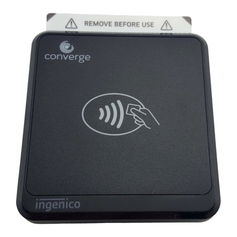
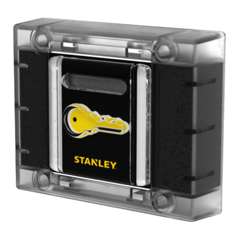
ASC ACR1281U-C1 User guide

www.acs.com.hk
Application Programming Interface V1.08
ACR1281U-C1
USBDualInterfaceReader

ACR1281U-C1 – Application Programming Interface [email protected]
Version 1.08 www.acs.com.hk
Page 2 of 96
Revision History
Release Date Revision Description Version Number
2011-08-19 ●Initial Release 1.00
2011-12-21
•Added Manual PICC Polling from ACR128
•Removed Buzzer Control OFF: 00
•Removed the following functions:
oBuzzer Status
oRead/Initialize Register Setting
oRead/Update Register
oAll Atmel Memory Card functions
oRead Interface Status
•Updated Sections 5.3.5 & 5.3.6: Set/Read
Default LED & Buzzer Behaviors
•Updated Sections 5.3.10 & 5.3.11:
Set/Read Automatic PICC Polling
●Updated description for Set/Read Antenna
Field
1.01
2012-07-18 •Updated Formatting 1.02
2013-01-23 •Updated Formatting
•Updated Section 2.0: Features 1.03
2013-07-11
•Updated Product Photo
•Added FIPS201 in Section 2.0: Features
•Updated Sections 5.3.5 & 5.3.6: Set/Read
Default LED & Buzzer Behaviors
•Updated Sections 5.3.10 & 5.3.11:
Set/Read Automatic PICC Polling
1.04

ACR1281U-C1 – Application Programming Interface [email protected]
Version 1.08 www.acs.com.hk
Page 3 of 96
Release Date Revision Description Version Number
2014-01-09
•Updated formatting
•Added Memory Card - ATMEL AT88SC15
and Memory Card - AT88SC101 /
AT88SC102 / AT88SC1003 in Contact
Smart Card Protocol Section 5.1
•Added Memory Card - ATMEL
AT88SC1608 in Contact Smart Card
Protocol Section 5.1
oSelect Card Type
oRead Memory Card
oWrite Memory Card
oVerify Password
oInitialize Authentication
oVerify Authentication
•Removed the following commands under
Section 5.3
oSet Auto PPS
oRead Auto PPS
oSet Antenna Field
oRead Antenna Field Status
oSet User Extra Guard Time Setting
oRead User Extra Guard Time Setting
oSet “616C” Auto Handle Option Setting
oRead “616C” Auto Handle Option
Setting
•Refresh Interface Status
1.05
2015-10-14 •Updated Section 5.3.10: Set Automatic
PICC Polling 1.06
2017-01-18
•Updated Section 2.0: Features
•Added Section 5.3.17 Set Auto PPS and
Section 5.3.18 Read Auto PPS
•Added Note in Appendix D. Escape
Command Example
•Removed FIPS201 in Section 2.0 Features
1.07
2018-03-20
•Updated Section 2.0: Features
oAdded CAC, PIV, PPS, and extended
APDU Support for Contact Interface
oAdded Short Circuit Protection Feature
o
Added REACH Compliance
1.08

ACR1281U-C1 – Application Programming Interface [email protected]
Version 1.08 www.acs.com.hk
Page 4 of 96
Table of Contents
1.0. Introduction ...............................................................................................................6
2.0. Features .....................................................................................................................7
3.0. ACR1281U-C1 Architecture......................................................................................9
3.1. Reader Block Diagram...........................................................................................................9
3.2. Communication between PC/SC driver and ICC, PICC and SAM........................................9
4.0. Hardware Design.....................................................................................................10
4.1. USB......................................................................................................................................10
4.1.1. Communication Parameters .......................................................................................10
4.1.2. Endpoints....................................................................................................................10
4.2. Contact Smart Card Interface..............................................................................................10
4.2.1. Smart Card Power Supply VCC (C1)..........................................................................10
4.2.2. Card Type Selection....................................................................................................10
4.2.3. Interface for Microcontroller-based Cards ..................................................................11
4.3. Contactless Smart Card Interface .......................................................................................11
4.3.1. Carrier Frequency.......................................................................................................11
4.3.2. Card Polling.................................................................................................................11
4.4. User Interface ......................................................................................................................11
4.4.1. Buzzer.........................................................................................................................11
4.4.2. LED .............................................................................................................................11
5.0. Software Design......................................................................................................12
5.1. Contact Smart Card Protocol...............................................................................................12
5.1.1. Memory Card – 1/2/4/8/16 kilobits I2C Card...............................................................12
5.1.2. Memory Card – 32/64/128/256/512/1024 kbits I2C Card...........................................15
5.1.3. Memory Card – ATMEL AT88SC153..........................................................................18
5.1.4. Memory Card – ATMEL AT88SC1608........................................................................22
5.1.5. Memory Card – SLE4418/SLE4428/SLE5518/SLE5528............................................26
5.1.6. Memory Card – SLE4432/SLE4442/SLE5532/SLE5542............................................31
5.1.7. Memory Card – SLE4406/SLE4436/SLE5536/SLE6636............................................37
5.1.8. Memory Card – SLE4404 ...........................................................................................42
5.1.9. Memory Card – AT88SC101/AT88SC102/AT88SC1003...........................................46
5.2. Contactless Smart Card Protocol........................................................................................54
5.2.1. ATR Generation..........................................................................................................54
5.2.2. ATR Format for ISO 14443 Part 3 PICCs...................................................................54
5.2.3. ATR Format for ISO 14443 Part 4 PICCs...................................................................56
5.2.4. Pseudo APDUs for Contactless Interface...................................................................57
5.3. Peripherals Control..............................................................................................................69
5.3.1. Get firmware version...................................................................................................69
5.3.2. LED Control.................................................................................................................70
5.3.3. LED Status..................................................................................................................71
5.3.4. Buzzer Control ............................................................................................................72
5.3.5. Set default LED and buzzer behaviors .......................................................................73
5.3.6. Read default LED and buzzer behaviors....................................................................74
5.3.7. Initialize cards insertion counter..................................................................................75
5.3.8. Read cards insertion counter......................................................................................76
5.3.9. Update cards insertion counter...................................................................................77
5.3.10. Set automatic PICC polling.........................................................................................78
5.3.11. Read automatic PICC polling......................................................................................80
5.3.12. Manual PICC polling ...................................................................................................81
5.3.13. Set PICC operating parameter....................................................................................82
5.3.14. Read PICC operating parameter ................................................................................83
5.3.15. Set exclusive mode.....................................................................................................84
5.3.16. Read exclusive mode..................................................................................................85
5.3.17. Set auto PPS...............................................................................................................86

ACR1281U-C1 – Application Programming Interface [email protected]
Version 1.08 www.acs.com.hk
Page 5 of 96
5.3.18. Read auto PPS ...........................................................................................................87
Appendix A. Basic program flow for contactless applications....................................88
Appendix B. Accessing MIFARE DESFire tags (ISO 14443-4)......................................89
Appendix C. Extended APDU Example ..........................................................................91
Appendix D. Escape Command Example ......................................................................93
Appendix E. Supported Card Types...............................................................................94
Appendix F. ACR128 Compatibility ................................................................................95
List of Figures
Figure 1 : ACR1281U-C1 Reader Block Diagram..................................................................................9
Figure 2 : ACR1281U-C1 Architecture...................................................................................................9
List of Tables
Table 1 : USB Interface Wiring.............................................................................................................10
Table 2 : Buzzer Event .........................................................................................................................11
Table 3 : LED Indicator.........................................................................................................................11
Table 4 : Blown Fuse Code Values......................................................................................................52
Table 5 : ISO 14443 Part 3 ATR Format..............................................................................................54
Table 6 : ISO 14443 Part 4 ATR Format..............................................................................................56
Table 7 : MIFARE 1K Memory Map......................................................................................................60
Table 8 : MIFARE 4K Memory Map......................................................................................................61
Table 9 : MIFARE Ultralight Memory Map............................................................................................62

ACR1281U-C1 – Application Programming Interface [email protected]
Version 1.08 www.acs.com.hk
Page 6 of 96
1.0.Introduction
ACR1281U-C1 DualBoost II is the second generation of ACS’s ACR128 DualBoost Reader.
ACR1281U-C1 is a powerful and efficient dual interface smart card reader, which can be used to
access ISO 7816 MCU cards, MIFARE® cards and ISO 14443 Type A and B contactless cards. It
makes use of the USB CCID class driver and USB interface to connect to a PC and accept card
commands from the computer application.
ACR1281U-C1 acts as the intermediary device between the computer and the card. The reader,
which communicates with a contactless tag, MCU card, SAM card, or the device peripherals (LED or
buzzer), will carry out a command issued from the computer. It has three interfaces namely the PICC,
ICC and SAM interfaces, which all follow the PC/SC specifications. The contact interface makes use
of the APDU commands as defined in ISO 7816 specifications. For contact MCU card operations,
please refer to the related card documentation and the PC/SC specifications.
This API document details how the PC/SC APDU commands are implemented for the contactless
interface, contact memory card support and device peripherals of ACR1281U-C1.

ACR1281U-C1 – Application Programming Interface [email protected]
Version 1.08 www.acs.com.hk
Page 7 of 96
2.0. Features
•USB Full Speed Interface
•CCID-compliant
•Smart Card Reader:
oContactless Interface:
Read/Write speed of up to 848 Kbps
Built-in antenna for contactless tag access, with card reading distance of up to 50 mm
(depending on tag type)
Supports ISO 14443 Part 4 Type A and B cards and MIFARE series
Built-in anti-collision feature (only one tag is accessed at any time)
Supports extended APDU (max. 64 KB)
oContact Interface:
Supports ISO 7816 Class A, B and C (5 V, 3 V and 1.8 V)
Supports CAC (Common Access Card)
Supports PIV (Personal Identity Verification Card)
Supports microprocessor cards with T=0 or T=1 protocol
Supports memory cards
Supports PPS (Protocol and Parameters Selection)
Features Short Circuit Protection
Supports extended APDU (max. 64 KBytes for T=1; max. 512+10 Bytes for T=0)
oSAM Interface:
One SAM Slot
Supports ISO 7816 Class A SAM cards
•Application Programming Interface:
oSupports PC/SC
oSupports CT-API (through wrapper on top of PC/SC)
•Built-in Peripherals:
oTwo user-controllable LEDs
oUser-controllable buzzer
•USB Firmware Upgradability
•Supports Android™ 3.1 and later1
•Compliant with the following standards:
oISO 14443
oISO 7816
oPC/SC
oCCID
oCE
oFCC
1Uses an ACS-defined Android Library

ACR1281U-C1 – Application Programming Interface [email protected]
Version 1.08 www.acs.com.hk
Page 8 of 96
oRoHS 2
oREACH
oMicrosoft® WHQL

ACR1281U-C1 – Application Programming Interface [email protected]
Version 1.08 www.acs.com.hk
Page 9 of 96
3.0.ACR1281U-C1 Architecture
3.1. Reader Block Diagram
Figure 1: ACR1281U-C1 Reader Block Diagram
3.2. Communication between PC/SC driver and ICC, PICC and
SAM
The protocol being used between ACR1281U-C1 and the PC is CCID. All communications between
ICC, PICC and SAM are PC/SC-compliant.
Figure 2: ACR1281U-C1 Architecture

ACR1281U-C1 – Application Programming Interface [email protected]
Version 1.08 www.acs.com.hk
Page 10 of 96
4.0. Hardware Design
4.1. USB
The ACR1281U-C1 connects to a computer through USB following the USB standard.
4.1.1. Communication Parameters
The ACR1281U-C1 connects to a computer through USB as specified in the USB Specification 2.0.
The ACR1281U-C1 is working in full-speed mode, i.e. 12 Mbps.
Pin Signal Function
1 VBUS +5 V power supply for the reader
2 D- Differential signal transmits data between ACR1281U-C1 and PC
3 D+ Differential signal transmits data between ACR1281U-C1 and PC
4 GND Reference voltage level for power supply
Table 1: USB Interface Wiring
Note:
For ACR1281U-C1 to function properly through USB interface, the device driver should be
installed.
4.1.2. Endpoints
The ACR1281U-C1 uses the following endpoints to communicate with the host computer:
Control Endpoint – For setup and control purposes.
Bulk-OUT – For commands to be sent from host to ACR1281U-C1 (data packet size is 64 bytes).
Bulk-IN – For response to be sent from ACR1281U-C1 to host (data packet size is 64 bytes).
Interrupt-IN – For card status message to be sent from ACR1281U-C1 to host (data packet size is 8
bytes).
4.2. Contact Smart Card Interface
The interface between the ACR1281U-C1 and the inserted smart card follows the specifications of
ISO 7816-3 with certain restrictions or enhancements to increase the practical functionality of the
ACR1281U-C1.
4.2.1. Smart Card Power Supply VCC (C1)
The current consumption of the inserted card must not be any higher than 50 mA.
4.2.2. Card Type Selection
Before activating the inserted card, the controlling PC always needs to select the card type through
the proper command sent to the ACR1281U-C1. This includes both memory card and MCU-based
cards.
For MCU-based cards the reader allows to select the preferred protocol, T=0 or T=1. However, this
selection is only accepted and carried out by the reader through the PPS when the card inserted in
the reader supports both protocol types. Whenever a MCU-based card supports only one protocol
type, T=0 or T=1, the reader automatically uses that protocol type, regardless of the protocol type
selected by the application.

ACR1281U-C1 – Application Programming Interface [email protected]
Version 1.08 www.acs.com.hk
Page 11 of 96
4.2.3. Interface for Microcontroller-based Cards
For microcontroller-based smart cards only the contacts C1 (VCC), C2 (RST), C3 (CLK), C5 (GND)
and C7 (I/O) are used. A frequency of 4.8 MHz is applied to the CLK signal (C3).
4.3. Contactless Smart Card Interface
The interface between the ACR1281U-C1 and the contactless card follows the specifications of ISO
14443 with certain restrictions or enhancements to increase the practical functionality of the
ACR1281U-C1.
4.3.1. Carrier Frequency
The carrier frequency for ACR1281U-C1 is 13.56 MHz.
4.3.2. Card Polling
The ACR1281U-C1 automatically polls the contactless cards that are within the field. ISO 14443-4
Type A, ISO 14443-4 Type B and MIFARE cards are supported.
4.4. User Interface
4.4.1. Buzzer
A monotone buzzer is used to show the “Card Insertion” and “Card Removal” events.
Events Buzzer
1. The reader is powered up and successfully initialized. Beep
2. Card Insertion Event (ICC or PICC) Beep
3. Card Removal Event (ICC or PICC) Beep
Table 2: Buzzer Event
4.4.2. LED
The LEDs are used for showing the state of the contact and contactless interfaces. The Red LED is
used for showing PICC status and Green LED for ICC.
Reader States Red LED
PICC Indicator Green LED
ICC Indicator
1. No PICC found or PICC is available but
not activated. A single pulse per ~ 5 seconds
2. PICC is available and activated. ON
3. PICC is operating. Blinking
4. ICC is available and activated. ON
5. ICC is unavailable or inactive. OFF
6. ICC is operating. Blinking
Table 3: LED Indicator

ACR1281U-C1 – Application Programming Interface [email protected]
Version 1.08 www.acs.com.hk
Page 12 of 96
5.0.Software Design
5.1. Contact Smart Card Protocol
5.1.1. Memory Card – 1/2/4/8/16 kilobits I2C Card
5.1.1.1. Select card type
This command powers down/up the selected card in the reader, and then performs a card reset after.
Command
Command Class INS P1 P2 Lc Card Type
Select Card Type FFh A4h 00h 00h 01h 01h
Response
Response Data Out
Result SW1 SW2
Where:
SW1 SW2 = 90 00h if the operation is completed successfully.
5.1.1.2. Select page size
This command chooses the page size to read in the card. The default value is an 8-byte page write. It
resets to the default value whenever the card is removed or the reader is turned off.
Command
Command Class INS P1 P2 Lc Page Size
Select Page Size FFh 01h 00h 00h 01h
Where:
Page Size (1 byte)
03h = 8-byte page write
04h = 16-byte page write
05h = 32-byte page write
06h = 64-byte page write
07h = 128-byte page write

ACR1281U-C1 – Application Programming Interface [email protected]
Version 1.08 www.acs.com.hk
Page 13 of 96
Response
Response Data Out
Result SW1 SW2
Where:
SW1 SW2 = 90 00h if the operation is completed successfully.
5.1.1.3. Read memory card
This command reads the memory card’s content from a specified address.
Command
Command Class INS Byte Address MEM_L
MSB LSB
Read Memory Card FFh B0h
Where:
Byte Address (2 bytes)
Memory address location of the memory card
MEM_L (1 byte)
Length of data to be read from the memory card
Response
Response Byte 1 … … Byte N SW1 SW2
Result
Where:
Byte (1…N) Data read from memory card.
SW1 SW2 = 90 00h if the operation is completed successfully.

ACR1281U-C1 – Application Programming Interface [email protected]
Version 1.08 www.acs.com.hk
Page 14 of 96
5.1.1.4. Write memory card
This command writes the memory card’s content to a specified address.
Command
Command Class INS Byte Address MEM_L Byte 1 … … Byte N
MSB LSB
Write Memory Card FFh D0h
Where:
Byte Address (2 bytes)
Memory address location of the memory card
MEM_L (1 byte)
Length of data to be read from the memory card
Byte (1…N) Data to be written to the memory card.
Response
Response Data Out
Result SW1 SW2
Where:
SW1 SW2 = 90 00h if the operation is completed successfully.

ACR1281U-C1 – Application Programming Interface [email protected]
Version 1.08 www.acs.com.hk
Page 15 of 96
5.1.2. Memory Card – 32/64/128/256/512/1024 kbits I2C Card
5.1.2.1. Select card type
This command powers down/up the selected card in the reader, and then performs a card reset after.
Command
Command Class INS P1 P2 Lc Card Type
Select Card Type FFh A4h 00h 00h 01h 02h
Response
Response Data Out
Result SW1 SW2
Where:
SW1 SW2 = 90 00h if the operation is completed successfully.
5.1.2.2. Select page size
This command chooses the page size to read in the card. The default value is an 8-byte page write. It
resets to the default value whenever the card is removed or the reader is turned off.
Command
Command Class INS P1 P2 Lc Page Size
Select Page Size FFh 01h 00h 00h 01h
Where:
Page Size (1 byte)
03h = 8-byte page write
04h = 16-byte page write
05h = 32-byte page write
06h = 64-byte page write
07h = 128-byte page write
Response
Response Data Out
Result SW1 SW2
Where:
SW1 SW2 = 90 00h if the operation is completed successfully.

ACR1281U-C1 – Application Programming Interface [email protected]
Version 1.08 www.acs.com.hk
Page 16 of 96
5.1.2.3. Read memory card
This command reads the memory card’s content from a specified address.
Command
Command Class INS Byte Address MEM_L
MSB LSB
Read Memory Card FFh
Where:
INS (1 byte)
B0h = For 32, 64, 128, 256, 512 kbit I2C card
1011 000*b; where * is the MSB of the 17 bit addressing = For 1024
kbit I2C card
Byte Address (2 bytes)
Memory address location of the memory card
MEM_L (1 byte)
Length of data to be read from the memory card
Response
Response Byte 1 … … Byte N SW1 SW2
Result
Where:
Byte (1…N) Data read from memory card.
SW1 SW2 = 90 00h if the operation is completed successfully.
5.1.2.4. Write memory card
This command writes the memory card’s content to a specified address.
Command
Command Class INS Byte Address MEM_L Byte 1 … … Byte N
MSB LSB
Write Memory
Card FFh
Where:
INS (1 byte)
D0h = For 32, 64, 128, 256, 512 kbit I2C card
1101 000*b; where * is the MSB of the 17 bit addressing = For 1024
kilobit I2C card

ACR1281U-C1 – Application Programming Interface [email protected]
Version 1.08 www.acs.com.hk
Page 17 of 96
Byte Address (2 bytes)
Memory address location of the memory card
MEM_L (1 Byte)
Length of data to be read from the memory card
Byte (1…N) Data to be written to the memory card.
Response
Response Data Out
Result SW1 SW2
Where:
SW1 SW2 = 90 00h if the operation is completed successfully.

ACR1281U-C1 – Application Programming Interface [email protected]
Version 1.08 www.acs.com.hk
Page 18 of 96
5.1.3. Memory Card – ATMEL AT88SC153
5.1.3.1. Select card type
This command powers down/up the selected card inserted in the card reader and performs a card
reset. It will also select the page size to be an 8-byte page write.
Command
Pseudo-APDU
Command Class INS P1 P2 Lc Card Type
Select Card Type FFh A4h 00h 00h 01h 03h
Response
Response Data Out
Result SW1 SW2
Where:
SW1 SW2 = 90 00h if the operation is completed successfully.
5.1.3.2. Read memory card
This command will read the Memory Card’s Content from specified address.
Command
Pseudo-APDU
Command Class INS P1 Byte Address MEM_L
Read Memory Card FFh 00h
Where:
INS (1 byte)
For reading zone 00b, INS = B0h
For reading zone 01b, INS = B1h
For reading zone 10b, INS = B2h
For reading zone 11b, INS = B3h
For reading fuse, INS = B4h
Byte Address (1 byte)
Memory address location of the memory card.
MEM_L (1 byte)
Length of data to be read from the memory card.

ACR1281U-C1 – Application Programming Interface [email protected]
Version 1.08 www.acs.com.hk
Page 19 of 96
Response
Response Byte 1 … … Byte N SW1 SW2
Result
Where:
Byte (1…N) Data read from memory card.
SW1 SW2 = 90 00h if the operation is completed successfully.
5.1.3.3. Write memory card
This command writes the memory card’s content from a specified address.
Command
Pseudo-APDU
Command Class INS P1 Byte
Address MEM_L Byte 1 … … Byte N
Write Memory
Card FFh 00h
Where:
INS (1 byte)
For reading zone 00b, INS = D0h
For reading zone 01b, INS = D1h
For reading zone 10b, INS = D2h
For reading zone 11b, INS = D3h
For reading fuse, INS = D4h
Byte Address (1 byte)
Memory address location of the memory card.
MEM_L (1 byte)
Length of data to be written to the memory card
Byte (1…N) Data to be written to the memory card.
Response
Response Data Out
Result SW1 SW2
Where:
SW1 SW2 = 90 00h if the operation is completed successfully.

ACR1281U-C1 – Application Programming Interface [email protected]
Version 1.08 www.acs.com.hk
Page 20 of 96
5.1.3.4. Verify password
This command verifies whether the memory card’s password matches the user’s entered PIN.
Command
Pseudo-APDU
Command Class INS P1 P2 Lc RP PW (0) PW (1) PW (2)
Verify
Password FFh 20h 00h 03h
Where:
PW (0), PW (1), PW (2) = Password to be sent to memory card.
P2 (1 Byte)
= 0000 00r pb
Where the two bits “r p” indicates the password to compare
r = 0: Write password,
r = 1: Read password,
p = Password set number
r p = 01b for the secure code.
Response
Response Data Out
Result SW1 ErrorCnt
Where:
SW1 = 90h
ErrorCnt (1 byte)
= Error Counter
FFh indicates the verification is correct. 00h indicates the password is locked
(exceed maximum number of retries). Other values indicate the current
verification is failed.
Table of contents
