Aseptico ADU-17A Manual

ADU-17A Express Air Portable Dental System
OPERATION and MAINTENANCE
INSTRUCTION MANUAL

TABLE OF CONTENTS:
Introduction . . . . . . . . . . . . . . . . . . . . . . . . .1
Package Contents . . . . . . . . . . . . . . . . . . . .1
Safety Precautions . . . . . . . . . . . . . . . . . . .2
Setting Up the Unit . . . . . . . . . . . . . . . . . . .3
Figure 1 - ADU-17A System . . . . . . . . . .3
Figures 2a thru 2e - Changing Voltage . .4
Figure 3 - Installing Instrument Holder . . .5
Figure 4 - Waste Tank Connections . . . .5
Figure 5 - Saliva Ejector Connection . . . .5
Operation Functions . . . . . . . . . . . . . . . . . .6
Operation . . . . . . . . . . . . . . . . . . . . . . . . . . .7
Figure 6 - Handpiece Controls . . . . . . . . .7
Sterilization & Maintenance . . . . . . . . . . . . .8
Figure 7 - TA-90D Syringe . . . . . . . . . . . .8
Troubleshooting . . . . . . . . . . . . . . . . . . . . . .9
Repacking Instructions . . . . . . . . . . . . . . .10
Symbol Definitions . . . . . . . . . . . . . . . . . . .11
Specifications . . . . . . . . . . . . . . . . . . . . . .12
Warranty . . . . . . . . . . . . . . . . . . . . . . . . . .13
P.O. Box 1548 • Woodinville, WA 98072
8333 216th Street S.E. • Woodinville, WA 98072
International (425) 487-3157 • Toll Free(800) 426-5913
To prevent injury to people and damage to property,
please heed relevant warnings and remarks. They
are marked as follows:
WARNING: Serious injury or death may result if
ignored.
CAUTION: Damage to property or the
environment may result if ignored.
NOTE: Important additional information
and hints.
i.
CONFORMS TO UL STD 60601-1;
CERTIFIED TO CSA STD C22.2 NO. 601.1

1.
Your new Aseptico Express Air Portable Dental System is the finest portable electric dental sys-
tem available. The ADU-17A features a handpiece control, 3-way air/water syringe, HVE and sali-
va ejector vacuum systems, a self contained water system, oilless air compressor, and vacuum
pump. The dual voltage system comes in a case with wheels and a handle for maximum portabili-
ty.
Congratulations
This system is engineered to provide many years of reliable service. Please read the instructions
provided in this manual to receive the best and longest service from your Aseptico equipment.
Separate manuals may be provided to cover the operation and maintenance of other accessories
for your unit.
PACKAGE CONTENTS:
• Portable Case with Compressor and Vacuum Pump
• TA-90D 3-Way Air/Water Syringe
• HVE and Saliva Ejector Vacuum Hoses with Valves
• Water Supply Bottle
• AA-42 Air Foot Control
• Power Cord
• Operation & Maintenance Manual
• Highspeed or Lowspeed Pneumatic Handpiece (Purchased separately)
• AWS-1C Cavitron Connector
• Two Spare 6A Fuses for 120V Operation

2.
SAFETY PRECAUTIONS:
Aseptico accepts no liability for direct or consequential injury or damage resulting from improper use,
arising in particular through the non-observance of the operating instructions, or improper preparation
and maintenance.
WARNING: Sterilize before first and all uses. Clean, disinfect, and sterilize new or repaired instru-
ments before first use. Only use sterilized handpieces and instruments during treatment.
Non-sterile handpieces and instruments may cause bacterial or viral infections. Always
sterilize instruments after operation.
CAUTION: Always examine unit components for damage before commencing treatment. Damaged
components must not be used and must be replaced.
WARNING: Use for intended purposes only. Failure to observe the operating instructions may result
in the patient or user suffering serious injury or the the product being damaged, possibly
beyond repair. Before using this product, make sure that you have studied and under-
stood the operating instructions.
WARNING: For use by qualified and trained personnel only.
WARNING: Do not install where there is a risk of an explosion. The Express Air is not intended for
operation in the presence of flammable anesthetics or gases.
WARNING: Always operate a high-speed handpiece with water coolant. Operating a high-speed
handpiece without water coolant can cause thermal injury to the patient and damage the
handpiece.

3.
SETTING UP THE UNIT:
FIG. 1 - ADU-17A Express Air
CLIP-ON
INSTRUMENT HOLDER
3-WAY
AIR/WATER SYRINGE
HIGH VOLUME
VACUUM (HVE)
VOLTAGE
SELECTOR
MODULE
WASTE TANK
WASTE TANK
TIE-DOWN
WATER SUPPLY
BOTTLE
LOW VOLUME VACUUM
(SALIVA EJECTOR)
FOOT
PEDAL
ON/OFF
SWITCH
CASE HANDLE
RESERVOIR
CONNECTOR
COMPRESSOR
AND FAN
HOUSING
COOLANT
ON/OFF
SWITCH
AIR CON-
TROL
VALVE
CAVITRON
CONNECTOR
HANDPIECE
COOLANT
CONTROL
VALVE

4.
120V
Indicator
Fig. 2a
240V
Indicator
Voltage Selector Module
Fig. 2d
Fig. 2b
Fig. 2c
Fig. 2e
1. Unpack the ADU-17A Case.
2. Verify that the Voltage Selector Insert is config-
ured properly by checking the voltage indicator
on the Voltage Selector Module (Figure 2a). The
Voltage Module is located on the lower left of
the Motor Cover. The Voltage Selector Insert
must be installed in the “120” position for 120V
60Hz operation or in the “240” position for 230V
50Hz operation.
To switch the voltage configuration, disconnect
power cord and insert a small flat screwdriver
under the locking tab in the front of Selector
Module. Gently depress tab until the fuse hous-
ing releases (Figure 2b). Carefully remove fuse
housing to reveal Voltage Selector Insert (Figure
2c). Pull insert out of housing, turn it around and
reinsert into housing with proper voltage indica-
tor facing out (Figure 2d).
IMPORTANT: For 120V use, check that the
Fuse in use is a 6A medium time delay; for
230V use, check that the Fuse is a 3A Slo-Blo
type. User may have to change fuses before
use.
For 230V use, confirm that the power cord is
correct for the country of usage and carries the
proper certifications.
Carefully reinstall fuses into Fuse Holder and
slide Holder back into Selector Module (Figure
1e). Apply pressure until locking tab snaps back
into position, producing a distinct clicking sound.
FUSES LOCATED
IN VOLTAGE
SELECTOR MOD-
ULE
WARNING:
ALWAYS DISCONNECT POWER TO
THE SYSTEM BEFORE OPENING
VOLTAGE SELECTOR MODULE
SETTING UP THE UNIT
Cont’d
:

5.
3. Mount the clip-on Holder to the extended handle of
the Case, as shown in Figure 3.
4. Attach a sterile handpiece to the ISO Type B
(4-Line) handpiece connector and place the hand-
piece in Holder (Fig. 3).
5. Remove the 3-way air/water Syringe from its travel
clip inside the Case and place it in the Holder.
6. Position the Waste Tank in the Case with the large
white connection to the rear left of the instrument
as shown in Figure 4. Attach the hose connector
coming from the Vacuum Motor to this large white
connection. Connect the High Volume Vacuum
(HVE) hose to the large gray connector located on
the front of the Waste Tank. Connect the Low
Volume Vacuum (Saliva Ejector) hose to the black
connector located on the front of the Tank.
Note: When attaching the Saliva Ejector hose to
the top of the Waste Tank, push in and rotate 1/4
turn (see Figure 5).
7. Secure Waste Tank by running Bungee Cord from
hooks on bottom panel overtop Tank lid. Verify that
the Waste Tank and vacuum lines are properly
installed. Hang the High Vacuum and Saliva
Ejector instruments on the Clip-On Holder.
8. Fill the Water Supply Bottle with clean water and
connect to the Water Reservoir Connector.
9. Attach the foot pedal and place on the floor.
Fig. 5
TO INSTALL SALIVA EJECTOR HOSE,
TURN CONNECTOR 1/4 TURN CLOCKWISE
VACUUM LINE
WITH QUICK
DISCONNECT
Fig. 4
Waste Tank
Water
Supply
Bottle
High
Volume
Connector
Vacuum
Motor
Connector
Bungee
Cord
Low
Volume
Connector
Water
Reservoir
Connector
Clip-On
Holder
Handle
Fig. 3
3-Way
Syringe
HVE
Saliva Ejector
Handpiece

6.
c.) Unscrew and remove Bottle from cap.
d.) Fill Bottle with clean water.
e.) Screw Bottle into the Water Reservoir
Connector.
f.) Plug in the power cord.
6. HVE and SALIVA EJECTOR VACUUMS:
The Express Air is equipped with a 5-liter Waste
Tank, a High Volume (HVE) hose, and a Low
Volume (Saliva Ejector) hose. Both High and
Low Volume systems operate simultaneously
from the same vacuum source. To gain vacuum
on the HVE, open the HVE valve to full open and
close the Saliva Ejector Valve. To gain vacuum
on the Saliva Ejector, close the HVE and open
the Saliva Ejector to full open.
The vacuum Waste Tank contains a ball float
shutoff to prevent accidental overflow. The Tank
should be emptied when it is ¾ full.
The High Volume (HVE) vacuum system con-
tains a screen inside the Waste Tank container.
The screen is used for collecting large debris
upon vacuum intake. Clean screen when neces-
sary.
To empty the Waste Container:
a.) Unplug the power cord.
b.) Disconnect the hoses.
c.) Empty container.
d.) Reconnect hoses.
e.) Plug in power cord.
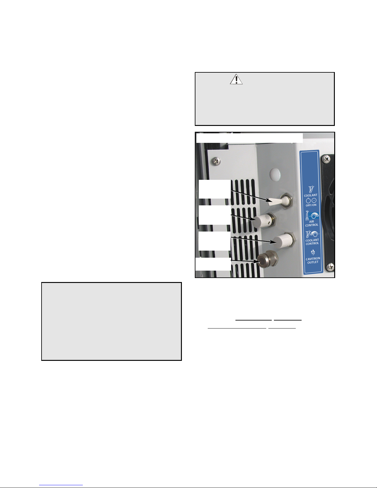
7. CAVITRON WATER OUTLET:
Provides water via standard 1/4” quick discon-
nect to independent Cavitron or scaler units
requiring a water supply.
The waste container has a ball float shutoff to
prevent accidental overflow. If the waste container
becomes full and the ball float activates, the vacu-
um motor may not restart, and could potentially
blow the fuse. Immediately empty waste container
to continue operation.
NOTE:
OPERATION FUNCTIONS:
1. ON/OFF SWITCH:
Turns the ADU-17A system On or Off.
2. AIR FOOT CONTROL:
The handpiece only operates when the foot
pedal is depressed. When the foot pedal is not
being used, the vacuum and syringe remain
operational
3. HANDPIECE CONTROLS:
a.) Off/On Coolant Toggle Switch - Turns
Handpiece water coolant On/Off.
b.) Air Control Switch - Allows adjustment of air
pressure to the Handpiece.
c.) Coolant Control Switch - Allows adjustment
of water coolant to the Handpiece.
4. THREE-WAY AIR/WATER SYRINGE:
- Pressing the left button dispenses water.
- Pressing the right button dispenses air.
- Pressing both buttons simultaneously
dispenses an air/water mist.
5. WATER SUPPLY BOTTLE:
The Express Air incorporates a self contained
pressurized water system. This system consists
of a 1-liter white bottle, which dispenses water
through the handpiece and 3-Way Air/Water
Syringe. The Water Supply Bottle threads into
the Reservoir Connector, located in the upper
right corner of the case.
To refill the Water Supply Bottle:
a.) Before removing the Bottle for refilling,
unplug the power cord from the Express Air
unit.
b.) Release pressure from Bottle by slightly
loosening bottle from reservoir connector
approximately 1/8-turn, or by depressing the
air button on the 3-Way Syringe.
THE WATER SUPPLY BOTTLE IS
PRESSURIZED DURING OPERATION.
DEPRESSURIZE BOTTLE BEFORE
REMOVAL BY SLIGHTLY LOOSENING
BOTTLE FROM RESERVOIR CONNEC-
TOR.
WARNING:

7.
OPERATION:
1. Connect the power cord to the Express
Air Unit and plug into appropriate power
source.
IMPORTANT: Ensure that the Voltage
Selector Insert is properly configured for
the power source - Refer to Page 4.
2. FOOT PEDAL OPERATION:
a. Turn the On/Off Switch on the front of
the Fan Housing to the 'ON' (I) position.
The vacuum and syringe will become
operational.
b. Depress the Foot Pedal: The handpiece
will activate. The Syringe, HVE, and
Saliva Ejector will remain operational.
3. Depress the foot pedal to operate the
handpiece. Adjust the air pressure and
water coolant flow to the desired settings
(See Fig. 6). (Turn the water coolant con-
trol knob clockwise to decrease flow, or
counterclockwise to increase flow.)
4. Use the 3-Way Air/Water Syringe as nec-
essary for irrigation or drying.
5. Adjust the vacuum pressure by moving
the valves on both the HVE and saliva
ejector vacuum heads.
6. Empty the Vacuum Waste Tank when it is
3/4 full.
After the unit has been set up and you have
made yourself familiar with the system func-
tions, there are two operating modes to select
from:
• On/Off Switch Operation - Switch ‘ON’
activates the vacuum and 3-way air/water
syringe.
• Foot Pedal Operation - Depressing the
Foot Pedal activates the handpiece.
FIG. 6 - HANDPIECE CONTROLS
COOLANT
ON/OFF
SWITCH
AIR CON-
TROL
VALVE
COOLANT
CONTROL
VALVE
CAUTION:
Some new ADU-17A compressor motors might
require a 2-week “break-in” when first used. As a
precaution against stalling the compressor or pos-
sibly blowing the fuses during this break-in period,
it is recommended that the foot pedal be removed
from the System for approximately 5 minutes
before each initial daily startup, during the first 2
weeks of use.
CAVITRON
CONNECTOR
WARNING:
Always operate a high-speed handpiece with water
coolant. Operating a high-speed handpiece without
water coolant can cause thermal injury to the patient
and damage the handpiece. Consult the handpiece
manufacturer’s instructions for additional information.

8.
STERILIZATION AND MAINTENANCE:
Because of its simple design, the Aseptico ADU-17A Express Air requires very little maintenance. Any maintenance that
is needed can be performed in minutes.
BLEEDING THE SYSTEM
If the unit will not be used for an extended period of time, or the unit might be subjected to freezing conditions, you
should bleed the system. Simply empty the contents of the water supply tank and install the tank back into the cap.
Operate the air/water syringe and handpiece with water coolant ‘ON’ until just air comes through the water line. Pack
unit and store as normal.
HANDPIECE FLUSH
Flush the handpiece for about 5 seconds after every patient, and about 20 seconds at the beginning of each day.
GENERAL CLEANING
The external surfaces of the case should be cleaned using a soft cloth moistened with a mild detergent solution. Any
external surfaces of the unit that are contacted during use should be wiped down with a soft cloth moistened with a dis-
infectant at the beginning of each day and between each patient use.
WATER LINES
Disinfect the water lines weekly. Prepare a 1:10 bleach solution (1 part household bleach to 10 parts water). Remove
water reservoir and discard residual water. Replace empty water supply tank and air purge all waterlines. Fill water sup-
ply tank with bleach solution. Run bleach solution through all lines. Allow bleach solution to stand in lines for 10 minutes.
Remove water supply tank and discard bleach. Flush water supply tank and all lines thoroughly with
clean water. Air purge and leave lines dry until next clinical use.
VACUUM SYSTEM
The HVE and Saliva Ejector Valves are fully autoclavable. Remove the valves from the hoses before autoclaving. The
vacuum hoses should not be autoclaved. Clean hoses with a disinfectant solution.
SYRINGE TIPS
The ADU-17A unit features a three-way air/water syringe with quick-change autoclavable tips. To remove a tip, press on
the locking collar surrounding the tip socket and pull the used tip straight out of the socket (see Fig. 7). To insert a new
tip, press locking collar and push tip into socket as far as it will go. Release collar and gently tug on tip before using to
ensure that tip is securely locked into socket.
Syringe Tip Sterilization:
1) Remove contaminated syringe tip.
2) Remove all visible signs of contamination before autoclaving.
3) Autoclave tip at 132° C (270° F) for ten minutes.
4) Sterilize between each patient use.
NOTE: Since only the tips can be autoclaved, it is recommended that the Air/Water Syringe be bagged with a
disposable, single-use plastic sleeve between each patient use.
FIG. 7 DEPRESS
LOCKING COLLAR

9.
Problem:
Unit will not start
Unit starts but blows fuse
No water coming out
Insufficient vacuum
Insufficient handpiece operation
Compressor makes a chugging
sound and does not start up
properly
Correction:
Check system’s power connection.
Turn On/Off switch ON for operation.
Check that voltage selector module is set for source voltage.
Check fuse. If blown, replace with 6A/125V medium time delay fuse for 120V
operation, or a 3A/250V slo-blo fuse for 230V operation.
Check that voltage selector module is set for source voltage.
Check vacuum waste container. If full, immediately empty to continue operation.
Check vacuum hose assembly for blockage.
Check that fuse is correct for source voltage.
Check water supply tank for water level and verify that cap is tight.
Depress foot switch for 5+ sec. to pressurize supply tank.
Ensure the handpiece air control knob is not open (turned clockwise) all the way.
Check vacuum waste container. If full, immediately empty to continue operation.
Check vacuum hose assembly for blockage.
Check that waste container lid is properly seated and tightly secured.
Check that handpiece coolant ON/OFF toggle is “ON”.
Check that air control valve is turned up adequately
Check that handpiece tubing is untangled and not crimped.
Check handpiece connection for missing gasket.
Check for sufficient power source and avoid long light-grade extension cords
(Refer to Figure 8 Extension Cord Recommendations - below)
TROUBLESHOOTING:
EXTENSION CORD RECOMMENDATIONS:
Use only a 3-wire extension cord that has
a 3-blade grounding plug. Connect exten-
sion cord plug to a matching 3-slot recep-
tacle. Ensure that the extension cord is in
good condition and that its gage wire is
the correct size wire to carry the current
this product will draw. An undersized cord
is a potential fire hazard and will cause a
drop in line voltage, resulting in loss of
power and causing the product to over-
heat. Figure 8 indicates the correct size
cord for the length required and the
ampere rating listed on the product name-
plate. If in doubt, use the next heavier
gage cord. The smaller the gage num-
ber, the heavier the wire gage.
FIG. 8

10.
REPACKING INSTRUCTIONS:
1. Remove all accessories from the unit.
2. Remove water bottle and place in travel
pouch provided.
3. Position syringe in its holder on left side of
case (Fig. 10). Lay tube behind syringe,
next to waste tank.
4. Leave waste tank in place, with tie-downs
connected. Remove suction hoses from
waste tank, coil hoses, and place in bot-
tom of case behind the tank.
5. Place travel pouch with water bottle to the
left of the tank as shown.
6. Coil motor drive air line and place in
pouch. Place power cord and fuses in
pouch.
7. Tuck the blue water bottle tube between
the pouch and pouch flap as shown (Fig.
10). Close pouch flap.
8. Remove instrument clip-on holder from
extended handle and place in space locat-
ed above waste tank. Retract handle.
9. Detach foot pedal cable from connector,
coil cable around pedal, and place on top
of pouch as shown (Fig. 10).
10. Carefully close case lid, taking care not to
pinch any internal components.
WHEN TRANSPORTING UNIT, DO NOT
PLACE OBJECTS ON TOP OF CASE.
CAUTION:
FIG. 9

11.
Alternating current
Protective earth (ground)
Dangerous Voltage
Attention, consult
accompanying documents
SYMBOL DEFINITIONS:
Type B Equipment
Protect Against Dripping Water
Serial Number
IPX1
SN
Foot Switch
Handpiece - Air On/Off Switch
Coolant Adjustment Switches
Do Not Throw Into Trash Cavitron Connector
Fuses

12.
SPECIFICATIONS:
Size: 10.5” x 14.5” x 24”
(27 cm x 36 cm x 61 cm)
Volume: 1.81 cu. ft. (0.05 m3)
Weight: 43.5 lbs (19.7 kg)
Power Source: AC Dual Voltage Manual-Switching
120V / 230V at 50Hz / 60Hz
Current Rating: 6A at 120 VAC, or
3A at 230 VAC
Power Rating: 800 W
Operating Pressure: 45 - 50 PSI (344 kPa)
Average Air Flow Pressure: 30 PSI, 0.33 SCFM (275 kPa, 9.35 liters/min)
High Volume Vacuum: 3.0 SCFM @ -4” Hg (84.9 liters/min)
Low Volume Vacuum: 1.4 SCFM @ -1.5” Hg (39.6 liters/min)
Water Reservoir Capacity: 33.9 fl. oz. (1.0 liter)
Water Flow: 5.07 fl. oz./min (0.15 liter/min)
Waste Tank Capacity: 1.08 gal. (4.08 liters)
Noise Level: 72 dBA @ 3’4” (1 meter)
Environmental Conditions: Operating Temperature: 10° to 40° C (50° to 104° F)
Transport/Storage Temperature: -20° to 60° C (-4° to 140° F)
Relative Humidity: 10 to 90% non-condensing
Altitude: 0 to 3048 meters (0 to 10,000 feet)
Unit Duty Cycle: Continuous
This device has been tested and found to comply with the
emissions requirements of IEC 60601-1-2:2001-09. These
requirements provide reasonable protection against harmful
electromagnetic interference in a typical medical installation.
However, high levels of radio-frequency (RF) emissions from
electrical devices, such as cellular phones, may disrupt the per-
formance of this device. To mitigate disruptive electromagnetic
interference, position this device away from RF transmitters and
other sources of electromagnetic energy.
Classifications in accordance with UL-2601-1:
- Class II
- Type B Applied Parts
- Ordinary Protection
- Not suitable for use in the presence of a flam-
mable anesthetic mixture with air, oxygen, or
nitrous oxide.
Note: For reliable grounding, connect to receptacle
marked “Hospital Grade”.
Note: The power supply cord is the mains appliance dis-
connect means.
IMPORTANT NOTE:
When running the ADU-17A unit at 230VAC
50Hz, expect approximately 17% less vacuum
and pressure volume due to the slower turning
of the compressor.

13.
Aseptico warrants its products against defects in material or workmanship for a period of two
(2) years, from date of original invoice. Some handpieces are warranted for one year under
the same conditions. Other handpieces and expendable components, such as air turbines
and light bulbs, are covered by shorter warranty periods, or have no warranty. Aseptico's
sole obligation under product warranty is (at its sole option and discretion) to repair or
replace any defective component or product in part or whole. Aseptico shall be the sole
arbiter of such action.
In the event of alleged defect under warranty, the purchaser is to notify Aseptico's Customer
Service Department promptly. Customer Service will provide instructions, usually directing
that the product be returned for service. Shipment to Aseptico and the cost thereof is always
the responsibility of the purchaser.
Accidental misuse, inappropriate installation, or failure to perform directed maintenance
voids the warranty.
Aseptico does not assume, under this warranty, any risks or liabilities arising from the clinical
use of its products, whether or not such use involves coincidental utilization of products man-
ufactured by others.
WARRANTY

P/N: 420966
Rev. A
ECO 12704
10/2011
PRINTED IN
THE U.S.A.
P.O. Box 1548 • Woodinville, WA 98072
8333 216th Street SE • Woodinville, WA 98072
(425) 487-3157 • (800) 426-5913
Other manuals for ADU-17A
1
Table of contents
Other Aseptico Medical Equipment manuals

Aseptico
Aseptico penguin rfa User manual

Aseptico
Aseptico AEU-20 User manual

Aseptico
Aseptico AHP-85MB-X User manual

Aseptico
Aseptico DTC 2 AEU-26 Manual

Aseptico
Aseptico AEU-40 Endopex V Manual

Aseptico
Aseptico ADU-40CF Command Air Troubleshooting guide

Aseptico
Aseptico AEU-7000-70V Manual

Aseptico
Aseptico AEU-707A Manual

Aseptico
Aseptico CompriCart ADU-20B Manual