manuals.online logo
Brands
  1. Home
  2. •
  3. Brands
  4. •
  5. ashtech
  6. •
  7. GPS
  8. •
  9. ashtech Z-Xtreme RTK User manual

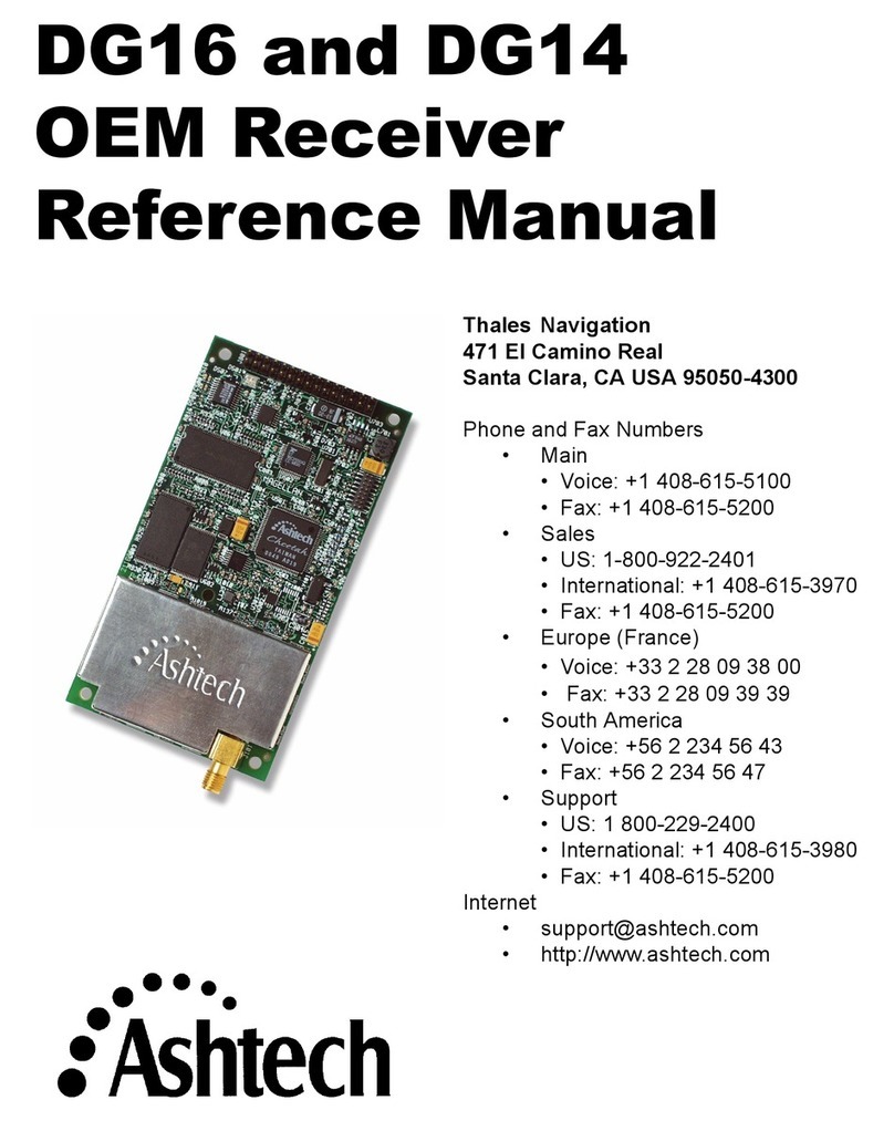
ashtech Z-Xtreme RTK User manual

Ashtech Z-Xtreme RTK / TDS Ranger - Survey Pro CE
Version 3.2.1 - Sales Support Document
RTK Demo – TDS Localization Method
The RTK Base will occupy an unknown control point, with assumed coordinates of
N-5000m, E-5000m and Elevation-500m. Perform a TDS GET to obtain the autonomous
WGS84 Latitude, Longitude and Ellipsoid Height for the RTK Base station. Perform
Single-Point Localization at the RTK Base Station. The resulting Scale Factor will equal
1.00000000 and the Rotation Angle will equal 0°00’ 00”.
You can demonstrate the capability of the RTK system from this single local control
point. You will be able RTK survey at relatively close distances to the RTK Base station.
The further the distance from the RTK Base station, (Single Point Localization) the
greater the distortions.
On the TDS Ranger, start the TDS Survey Pro CE software by double-tapping on the
Survey Pro icon, or from the Start | Programs | Survey Pro menu…
The TDS Survey Pro CE logo / splash screen will be displayed…
Figure 1
After a few seconds, the Logo / Splash screen will close automatically.
To manually close the Logo / Splash screen, simply tap anywhere on the screen.
Thales Navigation: ZXSS-TDS v3.2.1 Localization 1
The next screen…
Figure 2
The Welcome to Survey Pro dialog menu…
Select the “Create a New Job” menu… Tap the New… button.
The next screen…
Figure 3
Input a name for the New Job: RTK-Demo1
Next, Tap the Next > button…
Thales Navigation: ZXSS-TDS v3.2.1 Localization 2
The next screen…
Figure 4
Select the Options as shown above:
Next, Tap the Next button…
The next screen…
Figure 5
Enter the Coordinates as shown above:
Next, Tap the Finish button…
Thales Navigation: ZXSS-TDS v3.2.1 Localization 3
The next screen…
Figure 6
From the Survey Pro CE main menu, Tap on [ 2 ] JOB -[ A ] Settings menu…
The next screen…
Figure 7
In the Settings menu, Tap on the Center / Pull-Down Menu…
This is the Primary Settings Pull-Down menu for the Survey Pro CE software.
The basic Flow-Chart of the Settings menu, is to work your way down through menu,
Top to Bottom.
Tap on the Down-Arrow, select Receiver…
Thales Navigation: ZXSS-TDS v3.2.1 Localization 4
The next screen…
Figure 8
Select the Options as shown above:
Next, Tap on the Receiver settings… button,
The next screen…
Figure 9
Select the Options as shown above:
Next, Tap on the Base Radio Tab…
Thales Navigation: ZXSS-TDS v3.2.1 Localization 5
The next screen…
Figure 10
Select the Options as shown above:
Next, Tap on the General Tab…
The next screen…
Figure 11
Select the Options as shown above:
When finished verifying the GPS Receiver Settings – Tap OK …
Thales Navigation: ZXSS-TDS v3.2.1 Localization 6
This will return you to the Settings Menu…
Next, Tap on the Center Pull-Down menu,
Select Measure Mode…
The next screen…
Figure 12
Select the Options as shown above:
Next, Tap on the Center Pull-Down Menu – Select Projection…
The next screen…
Figure 13
Select the Options as shown above:
Thales Navigation: ZXSS-TDS v3.2.1 Localization 7
After you have selected the desired Projection Modes for the Demo, Tap OK…
This will return you to the Survey Pro CE Main menu…
At this stage of the demo, the TDS Ranger needs to be connected to the Base RTK
receiver. Both of the GPS receivers should be powered ON and tracking satellites.
The PDL Base Radio should also be powered ON.
Measure the GPS Antenna Heights for the RTK Base GPS Antenna and the RTK Rover
GPS antenna.
Next, Tap on the [ 3 ] Survey - [ A ] GPS Status menu
The next screen…
Figure 14
The GPS Status screen confirms you have established communications between the TDS
Ranger and the RTK base Receiver.
Notice the Receiver Mode: Off, this indicates the GPS receiver is still in STATIC mode,
configure the GPS Receiver for RTK Base mode.
Note the Receiver is already tracking and using 6 Satellites.
Thales Navigation: ZXSS-TDS v3.2.1 Localization 8
Next, Tap on the Sky View tab…
The next screen…
Figure 15
Next Tap on the Close button..
This will return you to Survey Pro CE Main menu…
Next, Tap on the [ 3 ] Survey - [ B ] Base Setup menu
The next screen…
Figure 16
Thales Navigation: ZXSS-TDS v3.2.1 Localization 9
Tap on the Setup… button,
The next screen…
Figure 17
Tap on the Down Arrow and Select – Choose from list…
The next screen…
Figure 18
Tap / Select Point 1, RTK Base, N-5000, E-5000, Elev. 500
Next, Tap the OK button…
Thales Navigation: ZXSS-TDS v3.2.1 Localization 10
The next screen…
Figure 19
Tap on the Setup HR button..
The next screen…
Figure 20
Select the Options as shown above:
The Antenna Type: Geodetic IV -GP: (P/N 701975-01). The –GP = No Ground plane.
In this example, The RTK Base GPS Antenna is mounted to a wooden tripod/Tribrach.
The HI Flag = Slant measure mark. Enter the Slant HI, measured to TGP
(Top of Ground Plane), Units = Meters , the Measured HI = 1.486m, the Serial Number
for the GPS Antenna = 5851
When finished with the data entry, Tap Set…
Thales Navigation: ZXSS-TDS v3.2.1 Localization 11
The next screen…
Figure 21
This returns to the Base Setup menu…
Tap on the Next > button…
The next screen…
Figure 22
In this menu, perform the TDS GET (GET Position From Rx.)
But, first input Average Position 60 Epochs before GET, then Tap
“GET Position From Rx.”
When using the TDS Localization, the recommended field procedure is to read / average
the WGS84 position from the RTK Base receiver for 60 seconds. This provides a better
base reference position. A one-second Get with bad PDOP spike and weak Satellite
Geometry may result in a suspicious RTK Base reference point.
Thales Navigation: ZXSS-TDS v3.2.1 Localization 12
The next screen…
Figure 23
Status Screen during 60-second from GET Autonomous Position…
When the 60-seconds is completed, the window automatically closes.
The next screen…
Figure 24
Resulting WGS84 Position for the RTK Base.
Tap on the Set button…
Thales Navigation: ZXSS-TDS v3.2.1 Localization 13
The next screen…
Figure 25
Tap on the Reset button…
This will start a new a data file in the GPS receiver’s internal PC Card memory,
for Post-Processing applications, (Code & Carrier Data).
The next screen…
Figure 26
Tap the OK button
This is the “Trigger” that switches the receiver from STATIC MODE into RTK BASE
MODE. The receiver is now configured as a RTK Base, the PDL Base Radio should now
begin to Transmit RTK corrections out to the RTK Rover(s)…
Thales Navigation: ZXSS-TDS v3.2.1 Localization 14
The next screen…
Figure 27
Tap on the OK button…
This screen informs the User, the current Localization will be discarded, (if the User Taps
OK), the RTK Rover must then re-occupy the Horizontal and Vertical control points,
then SOLVE & ACCEPT for the new Localization.
The next screen…
Figure 28
This is Current GPS Base Station Position
Tap on the Close button…
This will return you to the Survey Pro CE Main menu…
Thales Navigation: ZXSS-TDS v3.2.1 Localization 15
The next screen…
Figure 29
Next, Tap on [ 3 ] Survey - [ D ] Control Points
The next screen…
Figure 30
In this menu, select the point number for the RTK Base Point,
Calculate a Single Point Localization…
Thales Navigation: ZXSS-TDS v3.2.1 Localization 16
Control Points menu
+ Point: Tap on the Down Arrow for the Pull-Down menu…
Select “Choose from List” option, select Point 1, the RTK Base point,
Next, Tap on the Utilities | Projection menu button,
The next screens…
Figure 31
Next, Tap on the Localization Setup… menu button…
Figure 32
Press the “H” key on the Keyboard, then press the “V” key on the Keyboard,
or tap with the stylus under H and V adjacent to Point 1, this selects the Point(s) for the
Localization. After selecting Point 1, Tap the Solve button.
Thales Navigation: ZXSS-TDS v3.2.1 Localization 17
The next screen…
Figure 33
You have just performed a single Point Localization, holding the N-5000, E-5000, 500
Elevation coordinates, with the autonomous WGS84 position from the TDS GET:
Latitude 39°03’ 45.25178” N
Longitude 77°28’ 50.87388” W
Base Height 75.084m
Next, to accept the Localization, Tap on the Accept button…
Thales Navigation: ZXSS-TDS v3.2.1 Localization 18
The next screen…
Figure 34
Note the results of the Single Point Localization, the Scale Factor = 1.000000
The Rotation Angle = 0°00’ 00”. The data collector cannot compute the RMS
residuals on the control points, there’s not enough control points to compute these
residuals.
Tap on the Close button…
This will return you to Survey Pro CE Main menu…
Disconnect the TDS Ranger from the RTK Base Receiver,
Connect the TDS Ranger to the RTK Rover Receiver.
Thales Navigation: ZXSS-TDS v3.2.1 Localization 19
Next, select [ 3 ] Survey - [ C ] Rover Setup…
Figure 35
The next screen…
Figure 36
Thales Navigation: ZXSS-TDS v3.2.1 Localization 20

This manual suits for next models

1

Other ashtech GPS manuals

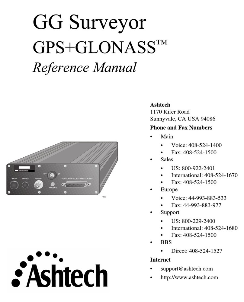
ashtech Z-Surveyor User manual

ashtech

ashtech Z-Surveyor User manual

ashtech Z-Xtreme Parts list manual

ashtech

ashtech Z-Xtreme Parts list manual

ashtech Z-sensor User manual

ashtech

ashtech Z-sensor User manual

ashtech Z-Xtreme User manual

ashtech

ashtech Z-Xtreme User manual

ashtech Z-Xtreme Parts list manual

ashtech

ashtech Z-Xtreme Parts list manual

ashtech ZY-12 Owner's manual

ashtech

ashtech ZY-12 Owner's manual

ashtech MobileMapper 10 User manual

ashtech

ashtech MobileMapper 10 User manual

ashtech Z-Xtreme User manual

ashtech

ashtech Z-Xtreme User manual

ashtech DG16 User manual

ashtech

ashtech DG16 User manual

ashtech GG Surveyor User manual

ashtech

ashtech GG Surveyor User manual

Popular GPS manuals by other brands

Leadtek LR9548S user manual

Leadtek

Leadtek LR9548S user manual

Magellan Z-Max Getting started

Magellan

Magellan Z-Max Getting started

MeiTrack MT90 user guide

MeiTrack

MeiTrack MT90 user guide

RoamEO RoamEO RoamEO GPS Pet Location System owner's manual

RoamEO

RoamEO RoamEO RoamEO GPS Pet Location System owner's manual

Garmin GPS 500 installation manual

Garmin

Garmin GPS 500 installation manual

Trivisio Colibri-Wireless user manual

Trivisio

Trivisio Colibri-Wireless user manual

TRACEEZ iCare Mini GPS user manual

TRACEEZ

TRACEEZ iCare Mini GPS user manual

Garmin fleet 660 owner's manual

Garmin

Garmin fleet 660 owner's manual

Mobile Alert 4G Mobile Alert Smart GPS Tracker user manual

Mobile Alert

Mobile Alert 4G Mobile Alert Smart GPS Tracker user manual

AVS GPS-T3G-S installation guide

AVS

AVS GPS-T3G-S installation guide

Altina GPS 9540 user manual

Altina

Altina GPS 9540 user manual

NorthStar 972 install guide

NorthStar

NorthStar 972 install guide

ROUTE 66 Mobile 8 user manual

ROUTE 66

ROUTE 66 Mobile 8 user manual

Navman ICN 550 user manual

Navman

Navman ICN 550 user manual

Holux GR-89 Specifications

Holux

Holux GR-89 Specifications

Leader LTC-905 instruction manual

Leader

Leader LTC-905 instruction manual

Satloc LiteStar IV Quick reference guide

Satloc

Satloc LiteStar IV Quick reference guide

FairwayIQ Smart-Tag user manual

FairwayIQ

FairwayIQ Smart-Tag user manual

manuals.online logo
manuals.online logoBrands
  • About & Mission
  • Contact us
  • Privacy Policy
  • Terms and Conditions

Copyright 2025 Manuals.Online. All Rights Reserved.