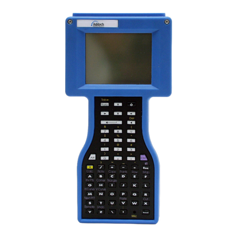
ashtech Z-Xtreme User manual

Z-Xtreme™ GPS Receiver
Operations & Reference Manual
Magellan Corporation
471 El Camino Real
Santa Clara, CA 95050-4300
Phone and Fax Numbers
•Main
• Voice: 408-615-5100
• Fax: 408-615-5200
•Sales
• US: 800-922-2401
• International: 408-615-3970
• Fax: 408-615-5200
• Europe
• Voice: 44-0118-931-9600
• Fax: 44-0118-931-9601
• Support
• US: 800-229-2400
• International: 408-615-3980
• Fax: 408-615-5200
• Internet
• http://www.ashtech.com
• http://www.magellangps.com

ii Z-Xtreme Operations and Reference Manual
Copyright Notice
Copyright © 2000 Magellan Corporation. All rights reserved.
No part of this publication or the computer programs described in it may be repro-
duced, translated, stored in a retrieval system, or transmitted in any form or by any
means, electronic, mechanical photocopying, recording, or otherwise, without prior
written permission of Magellan. Your rights with regard to this publication and the
computer programs are subject to the restrictions and limitations imposed by the
copyright laws of the United States of America (“U.S.A.”) and/or the jurisdiction in
which you are located.
Printed in the United States of America.
Part Number: 630843-01 Revision A
November, 2000
Trademarks
Z-Xtreme, Instant-RTK, Ζ−Tracking, and the Ashtech logo are trademarks of
Magellan Corp. Ashtech®is a registered trademark of Magellan Corp. All other prod-
ucts and brand names are trademarks or registered trademarks of their respective
holders.
FCC Statement
This equipment has been tested and found to comply with the limits for a Class A dig-
ital device, pursuant to part 15 of the FCC Rules. These limits are designed to pro-
vide reasonable protection against harmful interference when the equipment is
operated in a commercial environment. This equipment generates, uses, and can
radiate radio frequency energy and, if not installed and used in accordance with the
instruction manual, may cause harmful interference to radio communications. Opera-
tion of this equipment in a residential area is likely to cause harmful interference in
which case the user will be required to correct the interference at his own expense.

iii
SOFTWARE LICENSE AGREEMENT
IMPORTANT: BY OPENING THE SEALED DISK PACKAGE CONTAINING THE SOFTWARE MEDIA, YOU ARE
AGREEING TO BE BOUND BY THE TERMS AND CONDITIONS OF THE LICENSE AGREEMENT (“AGREE-
MENT”). THIS AGREEMENT CONSTITUTES THE COMPLETE AGREEMENT BETWEEN YOU (“LICENSEE”) AND
MAGELLAN CORPORATION (“LICENSOR”). READ THE AGREEMENT CAREFULLY. IF YOU DO NOT AGREE
WITH THE TERMS, RETURN THIS UNOPENED DISK PACKAGE AND THE ACCOMPANYING ITEMS TO THE
PLACE WHERE YOU OBTAINED THEM FOR A FULL REFUND.
LICENSE. LICENSOR grants to you a limited, non-exclusive, non-transferable, personal license (“License”) to (i)
install and operate the copy of the computer program contained in this package (“Program”) in machine acceptable
form only on a single computer (one central processing unit and associated monitor and keyboard) and (ii) to make
one archival copy of the Program for use with the same computer. LICENSOR and its third-party suppliers retain all
rights to the Program not expressly granted in this Agreement.
OWNERSHIP OF PROGRAMS AND COPIES. This License is not a sale of the original Program or any copies.
LICENSOR and its third-party suppliers retain the ownership of the Program and all copyrights and other proprietary
rights therein, and all subsequent copies of the Program made by you, regardless of the form in which the copies may
exist. The Program and the accompanying manuals (“Documentation”) are copyrighted works of authorship and con-
tain valuable trade secret and confidential information proprietary to the LICENSOR and its third-party suppliers. You
agree to exercise reasonable efforts to protect the proprietary interests of LICENSOR and its third-party suppliers in
the Program and Documentation and maintain them in strict confidence.
USER RESTRICTIONS. The Program is provided for use in your internal commercial business operations and must
remain at all times upon a single computer owned or leased by you. You may physically transfer the Program from
one computer to another provided that the Program is operated only on one computer at a time. You may not operate
the Program in a time-sharing or service bureau operation, or rent, lease, sublease, sell, assign, pledge, transfer,
transmit electronically or otherwise dispose of the Program or Documentation, on a temporary or permanent basis,
without the prior written consent of LICENSOR. You agree not to translate, modify, adapt, disassemble, decompile, or
reverse engineer the Program, or create derivative works of the Program or Documentation or any portion thereof.
TERMINATION. The License is effective until terminated. The License will terminate without notice from LICENSOR
if you fail to comply with any provision of this Agreement. Upon termination, you must cease all use of the Program
and Documentation and return them and any copies thereof to LICENSOR.
GENERAL. This Agreement shall be governed by and construed in accordance with the Laws of the State of Califor-
nia and the United States without regard to conflict of laws and provisions thereof and without regard to the United
Nations Convention on Contracts for the International Sale of Goods.
Unless modified in writing and signed by both parties, this warranty is understood to be the complete and exclusive
agreement between the parties, superseding all prior agreements, oral or written, and all other communications
between the parties relating to a warranty of the Product. No employee of Magellan or any other party is authorized to
make any warranty in addition to those made in this document. This warranty allocates the risks of product failure
between Magellan and the buyer. This allocation is recognized by both parties and is reflected in the price of the
goods. The buyer acknowledges that it has read warranty, understands it, and is bound by its terms.
This limited warranty is governed by the laws of the State of California, without reference to its conflict of law provi-
sions or the U.N. Convention on Contracts for the International Sale of Goods.
To the extent the foregoing provisions differ from the terms of the sales contract between the buyer
and Magellan Corporation, the sales contract will take precedence. The sales contract contains
procedural qualifications and other contractual terms relating to the foregoing provisions.
iv Z-Xtreme Operations and Reference Manual
DISCLAIMER OF WARRANTIES AND LIMITATION OF LIABILITY
LICENSOR AND ITS THIRD-PARTY SUPPLIERS MAKE NO WARRANTIES OR REPRESENTATIONS, EXPRESS
OR IMPLIED, REGARDING THE PROGRAM, MEDIA, DOCUMENTATION, RESULTS OR ACCURACY OF DATA
AND HEREBY EXPRESSLY DISCLAIM ANY WARRANTIES OF MERCHANTIBILITY AND FITNESS FOR A PAR-
TICULAR PURPOSE AND NONFRINGEMENT. LICENSOR AND ITS THIRD PARTY SUPPLIERS DO NOT WAR-
RANT THE PROGRAM WILL MEET YOU REQUIREMENTS OR THAT ITS OPERATION WILL BE
UNINTERRUPTED OR ERROR-FREE.
LICENSOR, its third-party suppliers, or anyone involved in the creation or delivery of the Program or Documentation
to you shall have no liability to you or any third-party for special, incidental, indirect or consequential damages
(including, but not limited to, loss of profits or savings, downtime, damage to or replacement of equipment or prop-
erty, or recovery or replacement of programs or data) arising from claims based in warranty, contract, tort (including
negligence), strict liability, or otherwise even if LICENSOR and its third-party have been advised of the possibility of
such claim or damages. The liability of LICENSOR and its third-party suppliers for direct damages shall not exceed
the actual amount paid for the program license.
Some States do not allow the exclusion of limitation of implied warranties or liability for incidental or consequential
damages, so the above limitations or exclusions may not apply to you.
MANUAL DISCLAIMER
THIS MANUAL IS PROVIDED “AS IS”; MAGELLAN MAKES NO WARRANTIES TO ANY PERSON OR ENTITY
WITH RESPECT TO THE SUBJECT MATTER OR USE OF INFORMATION CONTAINED HEREIN OR ANY
DERIVATIVES THEREOF OR ANY SERVICES OR LICENSES. MAGELLAN DISCLAIMS ALL IMPLIED WARRAN-
TIES, INCLUDING, WITHOUT LIMITATION, WARRANTIES OF MERCHANTABILITY AND FITNESS FOR A PAR-
TICULAR PURPOSE AND NONINFRINGEMENT. FURTHER, MAGELLAN DOES NOT WARRANT, GUARANTEE,
OR MAKE ANY REPRESENTATIONS REGARDING THE USE, OR THE RESULTS OF THE USE, OF THIS MAN-
UAL IN TERMS OF CORRECTNESS, ACCURACY, RELIABILITY, OR OTHERWISE. THIS PUBLICATION AND
FEATURES DESCRIBED HEREIN ARE SUBJECT TO CHANGE WITHOUT NOTICE.
U.S. GOVERNMENT RESTRICTED RIGHTS
The Program and Documentation are provided with RESTRICTIVE RIGHTS. Use, duplication, or disclosure by the
Government is subject to restrictions as set forth in subdivision (c)(1)(ii) of the Rights in Technical Data and Com-
puter Software clause at DFARS 252.227-7013 or subdivision 9(c)(1) and (2) of the Commercial Computer Software
- Restricted Rights 48 CFR 52.227.19, as applicable.
Should you have any questions concerning the License Agreement or the Limited Warranties and Limitation of Lia-
bility, please contact Magellan Corporation in writing at the following address: 471 El Camino Real, Santa Clara, CA
95050-4300

v
Introduction............................................................................... 1
Overview..................................................................................... 2
Functional Description ................................................................ 2
Memory Options ......................................................................... 3
Technical Specifications ............................................................. 4
Performance Specifications........................................................ 5
Receiver Options ........................................................................ 5
Option B - RTCM Base ............................................................ 6
Option U - RTCM Remote ....................................................... 6
Option E - Event Marker .......................................................... 7
Option X - External Frequency Reference ............................... 7
Option M - Remote Monitoring ................................................ 7
Option F - Fast Data Output .................................................... 7
Option T - Point Positioning ..................................................... 7
Option 3 - Observables—1, 2, 3 .............................................. 7
Option J - RTK Rover .............................................................. 8
Option K - RTK Base ............................................................... 8
Option I - Instant RTK .............................................................. 8
Equipment Description ............................................................ 9
Z-Xtreme Front Panel ................................................................. 9
Rear Panel................................................................................ 11
Pinouts...................................................................................... 13
Power .................................................................................... 13
Port (Fischer) Connectors ..................................................... 14
PCMCIA Card ........................................................................ 15
Battery/Charger ........................................................................ 17
Conditioning ........................................................................... 18
Charging ................................................................................ 19
Calibration ............................................................................. 19
Disposition ............................................................................. 20
Getting Started........................................................................ 21
Memory Card ......................................................................... 21
Installation ............................................................................. 21
Removal ................................................................................ 22
Internal Battery ...................................................................... 22
Installation ............................................................................. 23
Removal ................................................................................ 24
Hardware Setup ..................................................................... 24
Applying Power ...................................................................... 25
Contents

vi
Receiver Initialization ............................................................. 25
PCMCIA Card ........................................................................ 25
Monitoring .............................................................................. 25
Monitoring via the Front Panel............................................ 25
Satellite Tracking ................................................................ 26
Position............................................................................... 26
Remaining Memory ............................................................ 27
Remaining Power ............................................................... 27
Monitoring via the Serial Ports............................................ 28
Satellite Monitoring .......................................................... 28
Position............................................................................ 28
Available Memory ............................................................ 28
Remaining Power ............................................................ 28
Setting Receiver Parameters ................................................. 28
Saving Parameter Settings .................................................... 28
Operations............................................................................... 31
LED Display Interface ............................................................ 31
General............................................................................... 31
Menus................................................................................. 32
System Information (SysInfo) ............................................. 33
Receiver Status (Survey:mode).......................................... 33
STATIC .................................................................................. 34
KINEMATIC ........................................................................ 35
RTK BASE.......................................................................... 35
Survey Configuration (SURVCONF) .................................. 36
STATIC............................................................................ 37
KINEMATIC ..................................................................... 37
RTK BASE....................................................................... 38
Data Recording (Sessions)................................................. 38
Miscellaneous Parameter (Settings)................................ 39
Language............................................................................ 40
Warning Messages ................................................................ 40
Data Recording ...................................................................... 44
Reformatting the PC Card .................................................. 44
PCMCIA File Structure and File Names ............................. 45
Data Modes ........................................................................ 46
Downloading Data ................................................................. 47
Index ......................................................................................... 49

vii
Figure 1.1 Z-Xtreme GPS Receiver ................................................................... 1
Figure 2.1 Z-Xtreme Front Panel Closed ........................................................... 9
Figure 2.2 Z-Xtreme Front Panel Open ........................................................... 10
Figure 2.3 Z-Xtreme Rear Panel...................................................................... 11
Figure 2.4 Power Connector Pin Layout .......................................................... 13
Figure 2.5 Serial Port Pin Layout ..................................................................... 14
Figure 2.6 PCMCIA Card ................................................................................. 15
Figure 2.7 Lithium-ion Battery.......................................................................... 17
Figure 2.8 Battery in Battery Charger with AC Adapter ................................... 19
Figure 3.1 Memory/Battery Door...................................................................... 21
Figure 3.2 Installing an Internal Battery ........................................................... 23
Figure 3.3 Removing an Internal Battery ......................................................... 24
Figure 4.1 Display Menu Tree.......................................................................... 32
Figure 4.2 File Naming Convention ................................................................. 46
List of Figures

viii
Reliance Fundamentals

ix
Table 1.1 Technical Specifications. . . . . . . . . . . . . . . . . . . . . . . . . . . . . . . .4
Table 1.2 Accuracy as Function of Mode . . . . . . . . . . . . . . . . . . . . . . . . . . .5
Table 1.3 Z-Extreme Options . . . . . . . . . . . . . . . . . . . . . . . . . . . . . . . . . . . .5
Table 2.1 Controls and Indicators . . . . . . . . . . . . . . . . . . . . . . . . . . . . . . .10
Table 2.2 Z-Xtreme Rear Panel Description . . . . . . . . . . . . . . . . . . . . . . .11
Table 2.3 Power Connector Pinouts. . . . . . . . . . . . . . . . . . . . . . . . . . . . . .13
Table 2.4 Serial Port Pinout Description . . . . . . . . . . . . . . . . . . . . . . . . . .14
Table 2.5 PCMCIA Specifications . . . . . . . . . . . . . . . . . . . . . . . . . . . . . . .15
Table 2.6 Battery Indications . . . . . . . . . . . . . . . . . . . . . . . . . . . . . . . . . . .17
Table 4.1 Control Buttons. . . . . . . . . . . . . . . . . . . . . . . . . . . . . . . . . . . . . .31
Table 4.2 Main Menu Description. . . . . . . . . . . . . . . . . . . . . . . . . . . . . . . .33
Table 4.3 Survey Status Information . . . . . . . . . . . . . . . . . . . . . . . . . . . . .34
Table 4.4 Time Parameters . . . . . . . . . . . . . . . . . . . . . . . . . . . . . . . . . . . .34
Table 4.5 Selectable Recording Intervals. . . . . . . . . . . . . . . . . . . . . . . . . .37
Table 4.6 Selectable Data Types . . . . . . . . . . . . . . . . . . . . . . . . . . . . . . . .38
Table 4.7 Selectable Baud Rates. . . . . . . . . . . . . . . . . . . . . . . . . . . . . . . .39
Table 4.8 Selectable Languages . . . . . . . . . . . . . . . . . . . . . . . . . . . . . . . .40
Table 4.9 Front Panel Warnings. . . . . . . . . . . . . . . . . . . . . . . . . . . . . . . . .41
Table 4.10 Z-Family Recording Modes . . . . . . . . . . . . . . . . . . . . . . . . . . . .47
Table 4.11 File Types. . . . . . . . . . . . . . . . . . . . . . . . . . . . . . . . . . . . . . . . . .48
List of Tables

x

Introduction 1
Introduction
Introduction
The Z-Xtreme GPS receiver, Figure 1.1, presents a powerful and economical
alternative to conventional surveying equipment for the GPS community. Designed to
support an expanding variety of surveying applications, including land/boundary/
cadastral surveys, route surveys, construction, and as-built surveys, the 12-channel,
dual-frequency receiver integrates technological advances in microprocessor design,
data storage, and power management. Retaining the functionality of a complete
surveying system, the Z-Xtreme fits into an improved, lighter, and more ergonomic
enclosure. Incorporating Ashtech’s patented Z-Tracking technology to mitigate the
effects of Anti-Spoofing (AS), the Z-Xtreme provides increased tracking ability under
adverse satellite visibility conditions such as under tree canopy, in canyons, or
between buildings.
The Z-Xtreme operates on just 6 watts and includes an internal battery capable of 10
hours of continuous operation. For longer operations, the Z-Xtreme offers an external
power input. The receiver also includes internal memory in the form of a removable
standard 16Mb PCMCIA card expandable up to 85 Mb. Due to performance and
popularity, many third-party application software companies have developed their
Figure 1.1 Z-Xtreme GPS Receiver

2 Z-Xtreme Operations and Reference Manual
application-specific packages to work directly with the receiver. The Z-Xtreme
receiver works with a wide choice of controller software and data collectors,and
provides a full range of accessories to make surveying simple and efficient.
Incorporating an integrated, optimized keyboard/display, the system supports
collection and post-processing of static, rapid static, and kinematic data without the
need for an external handheld display/controller . The unit functions as a base station
and/or rover for real-time code and code/carrier RTCM differential GPS usage. To
support the requirement for real-time centimeter-level surveying solutions, an optional
UHF or spread spectrum radio is incorporated into the receiver, providing a
configured portable and integrated real-time GPS surveying system. The receiver can
be configured as a continuous operating reference station (CORS) for surveying,
GIS, geological, or other scientific monitoring applications.
Overview
The Z-Xtreme processes signals from the GPS satellite constellation, deriving real-
time position, velocity, and time measurements. Twelve dedicated separate and
parallel channels extract Coarse/Acquisition (C/A) code-phase, and carrier-phase
measurement on the L1 (1575 MHz) band, and Precise (P) code phase and carrier
phase measurement on the L1 and L2 (1227 MHz) bands.
The Z-Xtreme receives satellite signals via an L-band antenna and low-noise
amplifier (LNA). The receiver operates stand-alone and as a base (reference) station
or remote (rover) station providing real-time differential GPS operation for code, and
real-time kinematic (RTK) operation for carrier phase. The unit implements the RTCM
SC 104 V2.2 standard for differential and RTK operation. These features allow the Z-
Xtreme to achieve centimeter accuracy while being compatible for differential and
RTK operation with any other receiver that implements the RTCM standard.
Functional Description
The receiver is activated when either an internal battery has been inserted, or an
external power supply has been connected to the power connector, and the power
push-button is pushed to ON. After self-test, the receiver initializes its 12 channels
and begins searching for all space vehicles (SV) within the field of view of the
antenna. The receiver can track all Block I and Block II GPS SVs. All 32 PRN
numbers as specified in Navstar GPS Space Segment/Navigation User Interfaces,
ICD-GPS-200, Revision B are internally coded. As the receiver acquires (locks onto)
each SV, it notes the time and collects the ephemeris data about the orbit of that SV,
and almanac data about the orbits of all the SVs in the constellation.

Introduction 3
Introduction
The receiver features 12-parallel channel/12-SV all-in-view operation; each of up to 12
visible SVs can be assigned to a channel and then continuously tracked. Each SV
broadcasts almanac and ephemeris information every 30 seconds, and the unit
automatically records this information in its non-volatile memory. The unit has an L1/
L2-band radio frequency (RF) port and four RS-232 serial input/output (I/O) ports.
Ports A, B, and C are capable of two-way communication with external equipment.
Port D is capable of RTCM operation when using the optional internal radio link.
The RF circuitry receives satellite data from a GPS antenna and LNA via a coaxial
cable, and can supply +5V to the antenna/LNA by means of that cable. No separate
antenna power cable is required. Typical power consumption is approximately 6.0
watts even when powering an LNA.
The receiver incorporates three multi-colored LEDs. A radio data status LED blinks
green when valid radio data has been received. A memory storage status LED blinks
green when data is stored to the memory card. A satellite/power status LED blinks
green for each satellite tracked, and blinks red between satellites tracked count to
depict power-on status.
The receiver collects Coarse Acquisition (C/A) code-phase (pseudo-range) and full
wavelength carrier phase measurement on L1 frequency (1575 MHz), Precise (P)
code phase (pseudo-range) and full wavelength carrier phase on L1 and L2 frequency
(1227 MHz). All data can be stored on the internal PCMCIA card. The receiver permits
uninterrupted use even when Anti-Spoofing (AS) is turned on. When AS is on, the
receiver automatically activates Ashtech’s patented Z-tracking mode that mitigates the
effects of AS. The accuracy when AS is on is the same as when AS is off.
Memory Options
The amount of data the Z-Xtreme can retain depends upon the PCMCIA card and the
recording interval. You can verify the amount of memory by going to the Memory
Status (MEM:***%) menu under the SYSINFO menu displayed on the front panel. You
can also verify the amount of memory by sending the $PASHQ,FLS,0 command (for
more information on commands, refer to the Z-Xtreme Technical Reference Manual).

4 Z-Xtreme Operations and Reference Manual
Technical Specifications
Table 1.1 lists the technical specifications of the Z-Xtreme.
Table 1.1Technical Specifications
Characteristic Specifications
Tracking 12 channels L1 CA/PL1 and PL2
Size 3.“H x 7.75"W x 8.75"D
Weight 3.5 lb
Operating temperature -20° to +55°C (without internal battery)
Storage temperature -30° to +75°C (without internal battery)
Humidity 100%
Environment Resistant to wind-driven rain and dust to MIL-STD-810E
Power consumption, operating with
internal battery, at room temperature
(25° C), display disabled
6.0 watts
Power input 10 - 28VDC
Data storage From 16Mb up to 85 MB dependent upon PCMCIA card
Interface • Eight-character alphanumeric LED display
• Three dual-color LED
• Three external RS-232 ports via Fischer connectors
• One antenna connector
• Event marker and 1PPS via serial port connector
• Optional radio antenna connector
MEASUREMENT PRECISION
C/A (>10° elevation)
• Pseudo-range (raw/smooth)
• Carrier Phase
• 25cm/3.6cm
• 0.9mm
P-Code AS off (>10° elevation)
• L1 Pseudo-range (raw/smooth)
• L1 Carrier Phase
• L2 Pseudo-range (raw/smooth)
• L2 Carrier Phase
• 15cm/0.9cm
• 0.9mm
• 21cm/1.3cm
• 0.9mm

Introduction 5
Introduction
Performance Specifications
One of the most important functions of the receiver is providing real-time position with
accuracy ranging from less than 10 meters to centimeter level. Table 1.2 summarizes
the positioning modes and expected accuracy.
Specifications assume operation follows all the procedures recommended in the product manuals
utilizing Instant-RTK, post processing with Ashtech Solutions or Ashtech Office Suite for Survey.
High-multipath areas, high PDOP values, low satellite visibility, and periods of adverse atmospheric
conditions and/or other adverse circumstances will degrade system performance. All accuracy
specifications are RMS values.
Receiver Options
Table 1.3 lists the available options.
Table 1.2 Accuracy as Function of Mode
Positioning Mode
Typical Horizontal
Accuracy (2drms),
5 SVs, PDOP<4
Maximum Update
Rate
Maximum Operating
Range
Static, Rapid Static
Horizontal: 5mm + 1 ppm
Vertical: 10 mm + 1 ppm
5Hz (10 Hz optional) Several hundred kilometers
depending upon satellite
geometry.
Post-Processed
Kinematic
Horizontal: 1 cm + 1 ppm
Vertical: 2 cm + 1 ppm
5 Hz (10 Hz optional) Several hundred kilometers
depending upon satellite
geometry.
Real-Time Code
Differential
< 1 m
5 Hz (10 Hz optional) Several hundred kilometers
depending upon data link.
Real-time Z Kinematic
(Fine Mode)
Horizontal: 1 cm + 2 ppm
Vertical: 2 cm + 2 ppm
Azimuth (arc sec): 0.4 +
2.0/baseline (km)
5 Hz (10 Hz optional) Recommended: < 10 km
Maximum: 40 km
Table 1.3 Z-Extreme Options
Option Description
B RTCM differential base
U RTCM differential remote
E Event Marker

6 Z-Xtreme Operations and Reference Manual
Each option is represented by a letter or number presented in a certain order. You can
verify the installed options by going to the options table under the System Information
(SYSINFO) menu on the front panel. You can also verify the installed options by
issuing the $PASHQ,RID command to the receiver using an external handheld
controller or PC, as described in the Z-Xtreme Technical Reference Manual. The
$PASHQ,RID command displays the options on the external handheld controller or
PC. For example:
$PASHR,RID,UZ,30,UC00,BUEXMFT3JK,0A13*75
If the letter or number is displayed in the response message, the option is installed. If
the letter/number is not displayed, the option is not installed.
Option B - RTCM Base
The receiver can set as an RTCM differential base station and can output real-time
differential corrections when this option is enabled. The output will be in RTCM-104,
Version 2.2 format message types 1, 3, 6, 16, and 22, as well as RTCM Carrier
Differential 18, 19, 20, and 21. For messages 18, 19, 20, and 21, the K option is also
required.
Option U - RTCM Remote
The real-time differential corrections are available when this option is enabled. The
receiver will decode the RTCM-104, Version 2.2 format message types 1, 3, 6, 9, 16,
and 22 as well as types 18, 19, 20 and 21. For messages 18, 19, 20, and 21, the J
option is also required.
X External Frequency
M Remote monitor option
F Fast Data Output
T Point Positioning
1,2,3 Observables
J RTK Rover
KRTKBase
I Instant RTK
Table 1.3 Z-Extreme Options (continued)
Option Description

Introduction 7
Introduction
Option E - Event Marker
The E option enables the storage of event times created from a trigger signal. The
receiver measures and records event times with high accuracy (down to one
microsecond). The receiver stores an event time at the rising edge of the trigger signal
(or the falling edge on command) and the time is recorded in the receiver’s PC
memory card and/or output through the TTT NMEA message.
Option X - External Frequency Reference
The external frequency option X allows you to input an external frequency so you can
synchronize receiver data to an external clock. When enabled, its installation disables
the internal oscillator and uses the external frequency input only.
Option M - Remote Monitoring
The remote monitoring option allows you to use the REMOTE.EXE utility to access and
control the receiver via a modem from a remote location.
Option F - Fast Data Output
This option enables the receiver to be programmed to output both raw position data
and NMEA messages or record data (if a PCMCIA card is present in the receiver) at
user- selectable frequencies up to 10Hz. Without this option, only frequencies up to
5Hz are available.
Option T - Point Positioning
The T option allows you to put the receiver into point positioning mode using the
$PASHS,PPO command. Point positioning mode improves the accuracy of an
autonomous position of a static point.
Option 3 - Observables—1, 2, 3
This option determines the observables available in the receiver where:
1—CA code and P-code on L1/L2 (no carrier)
2—CA code and carrier, P-code on L1/L2 (no carrier)
3—CA code and carrier, P-code on L1/L2 and carrier

8 Z-Xtreme Operations and Reference Manual
Option J - RTK Rover
The J option allows the receiver to act as a rover station that utilizes the carrier
phase differential (both DBEN and RTCM message 18, 19, 20, and 21) data
transmitted from the base to compute differentially corrected positions. This option
requires the observables option to be 3. For RTCM messages type 18, 19, 20, and
21, the U option is required in addition to the J option.
Option K - RTK Base
The K option allows the receiver to act as a real-time Z base station which will output
carrier phase differential data. This option requires the observables option to be 3.
For RTCM 18/19 or 21/22, the B option is also required.
Option I - Instant RTK
The I option, an extension of the J option, allows the receiver to use the new RTK
system - Instant RTKTM which uses a new data processing strategy for integer
ambiguity initialization. The initialization time using Instant RTK typically requires a
single epoch of data if there are 6 or more satellites available with reasonable open
sky and low multipath. The baseline length should be 7 km or less.

Equipment Description 9
Equipment Description
This chapter provides a detailed description of the internal features of the Z-Xtreme.
Z-Xtreme Front Panel
The Z-Xtreme front panel, Figure 2.1 and Figure 2.2, allows you to control basic
receiver options as well as perform Static, Rapid Static, and Kinematic surveys.
Table 2.1 describes the functions of the front-panel controls and indicators.
Figure 2.1 Z-Xtreme Front Panel Closed
2
1
34

10 Z-Xtreme Operations and Reference Manual
Figure 2.2 Z-Xtreme Front Panel Open
Table 2.1 Controls and Indicators
Number Component Function
1 LED Display Display and input screen for receiver. Displays messages,
parameters, equipment status, and warning messages. The
screen displays eight characters at one time, while scrolling
messages larger than eight characters from right to left.
2 Up/Down/Enter buttons Operate these buttons for use with the LED display.
3 LED Indicators
• UHF/SS Radio Indicator
• Memory Storage Indicator
• Satellite Tracking/Power
Indicator
• Flashing green light indicates radio activity.
• Flashing green light indicates data stored to memory
activity; flashing red indicates data card full.
• Flashing green indicates satellites tracked;
flashing red indicates power applied to receiver.
4 On/Off Power button Turns unit on and off. Press and hold for 3 seconds to turn
off receiver.
5 Memory/Battery door Allows access to the memory card and battery.
6 Battery Eject button Ejects battery from internal battery connector.
7 Memory Card Eject button Ejects memory card from the memory card connector.
9
8
6
7
5
Other manuals for Z-Xtreme
3
Table of contents
Other ashtech GPS manuals

ashtech
ashtech Z-Xtreme Parts list manual

ashtech
ashtech DG16 User manual

ashtech
ashtech GG Surveyor User manual

ashtech
ashtech MobileMapper 10 User manual

ashtech
ashtech Z-Surveyor User manual

ashtech
ashtech ZY-12 Owner's manual

ashtech
ashtech Z-Xtreme Parts list manual

ashtech
ashtech Z-Xtreme User manual

ashtech
ashtech Z-Xtreme RTK User manual

ashtech
ashtech Z-sensor User manual
Popular GPS manuals by other brands

HLXTSZ
HLXTSZ GT003 user guide

Navman
Navman tracker plotter TRACKER 5600 Installation and operation manual

Maretron
Maretron GPS100 user manual

Garmin
Garmin ECHOMAP UHD2 owner's manual

Lowrance
Lowrance GlobalMap 5150C Operation instructions

Lowrance
Lowrance AirMap 300 Installation and operation instructions