Endo ELF-15 User manual

Users Manual
Spring Balancer
ELF-15 ELF-40 ELF-70
ELF-22 ELF-50
ELF-30 ELF-60
BMU-0015
Issued in December 2022
For safe and correct operation of the product, please be sure to read this manual and fully
understand its content before use
After reading, keep the manual safe so that you can find and use it readily
In case of resale or transfer of this product, make sure to transfer the manual to the new
owner

Spring Balancer Users Manual
1
CON EN S
1. Introduction ............................................................................................................. 2
Notation in this manual 2
Scope of warranty and liabilities for the equipment 3
Definition of intended users for this manual 3
Emergency contact in case of malfunctions 4
2. Precautions for handling ........................................................................................ 4
3. Unpacking and Installation ..................................................................................... 4
3-1 Packaging arrangement and transportation 4
3-2 Checks after unpacking 4
3-3 Disposal of packing materials 5
4. Product Description ................................................................................................ 5
4-1 Components 5
4-2 Operating environment 5
4-3 Product specifications 6
4-4 Applicable standards 6
5. Installation ............................................................................................................... 7
5-1 Preparation and checks before installation 7
5-2 Installation procedures 8
5-3 Post-installation checks 10
6. Usage ..................................................................................................................... 10
6-1 Pre-operation inspections and checks 10
6-2 Precautions for use 11
6-3 Operation method of the drum lock 12
6-4 Replacement of the tools (equipment) 12
6-5 Periodical inspections 13
7. roubleshooting .................................................................................................... 14
7-1 Countermeasures? 14
7-2 Releasing the fall-arrest device 14
8. Dimensional Drawing ............................................................................................ 15
9. Consumables and Special Accessories .............................................................. 15
10. Disposal of Product ............................................................................................ 15
Spring Balancer Users Manual
2
1.
Introduction
Thank you very much for your purchasing of the Spring Balancer To prevent any trouble and obtain the best
performance, please be sure to read this manual and fully understand its content
Notation in this manual
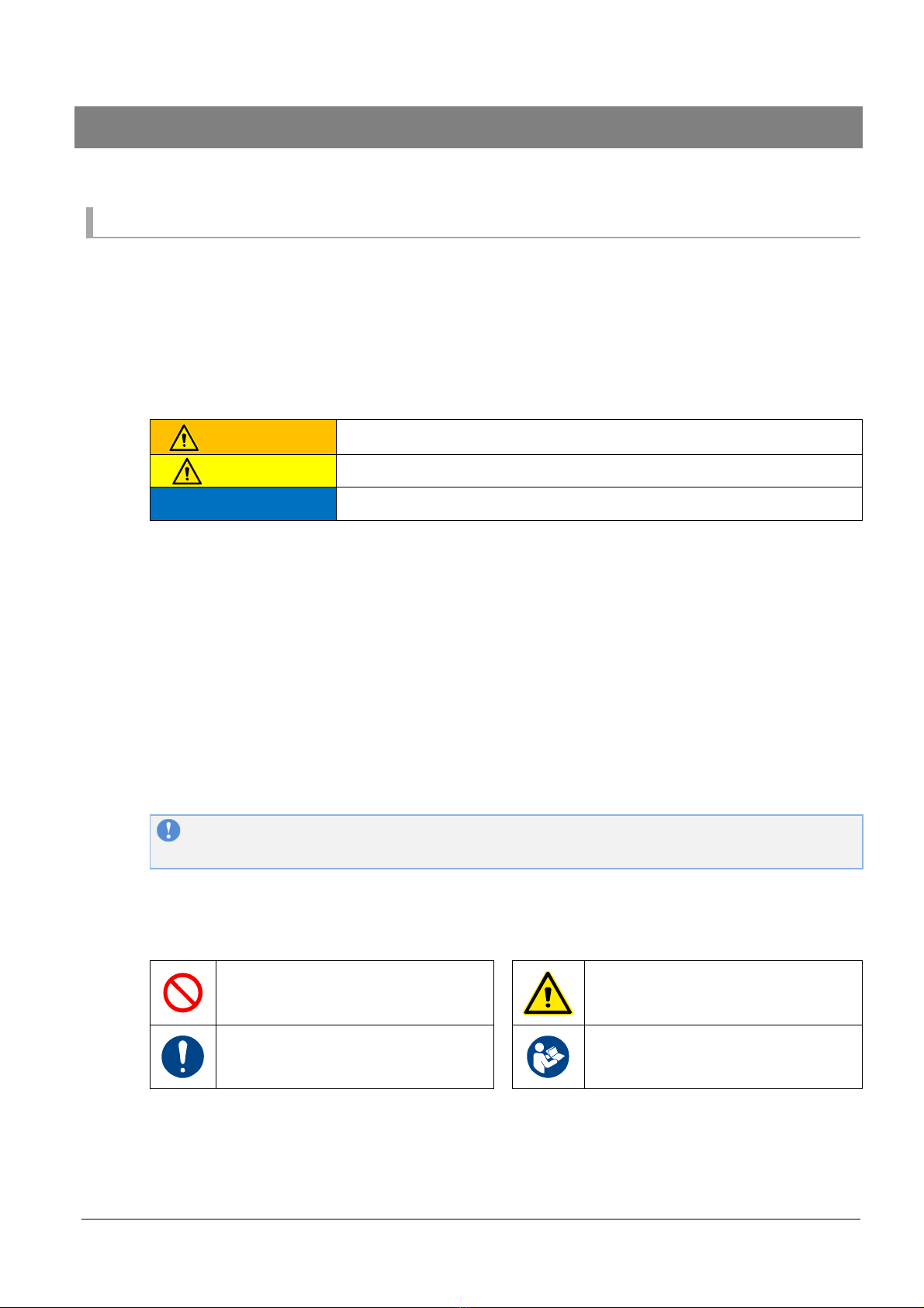
Hazard levels
This product is designed with ultimate priority on the safety of operators However, due to the nature of
the system, there are risks that cannot be removed
In this manual, the level of significance and risk is defined and indicated in three stages: “WARNING”,
“CAUTION”, and “NOTICE” Thoroughly read and fully understand the indicated items before operating
the product and performing maintenance procedures The indications for “WARNING”, “CAUTION”,
and “NOTICE” are in order of risk significance (WARNING > CAUTION > NOTICE) Their details are
described below
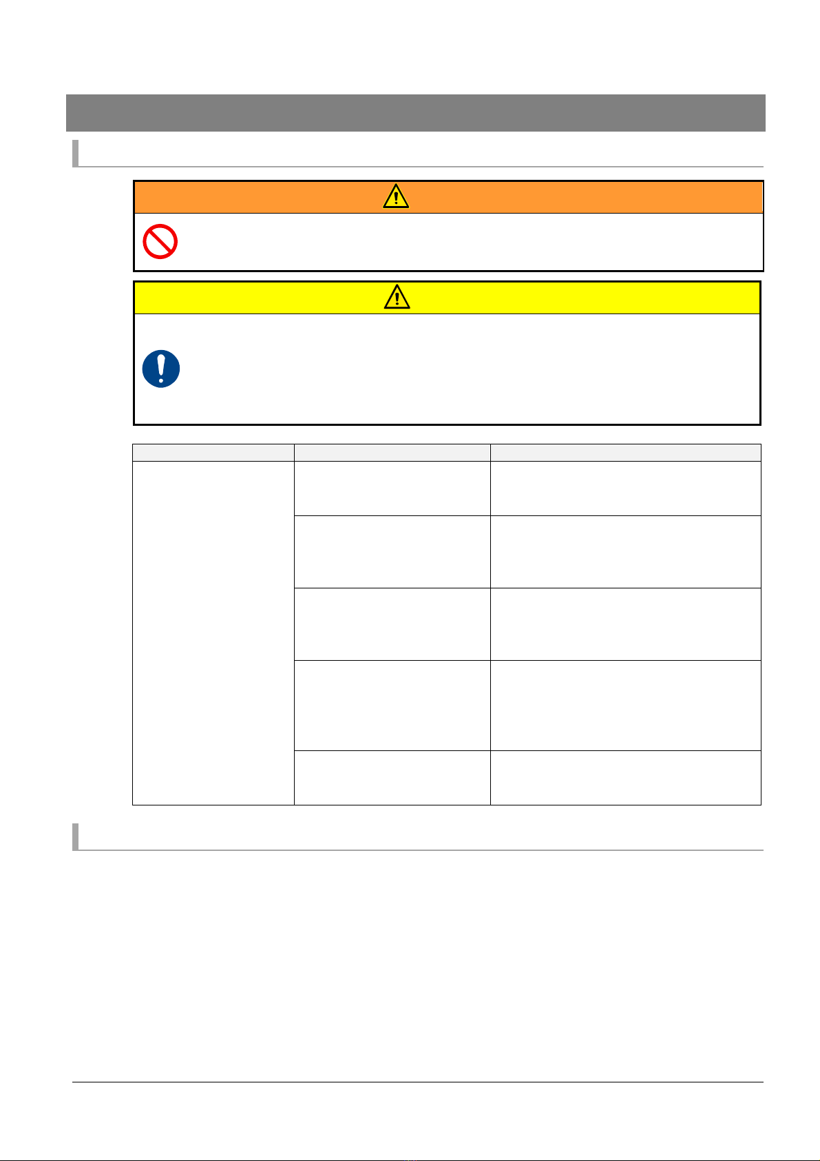
WARNING
A situation that, if mishandled, may cause death or serious disability
CAUTION
A situation that, if mishandled, may cause minor or moderate injury
NOTICE
Indicates a situation that, if mishandled, may cause property damage
The extent of the problem described above (disability, injury, and property damage) is defined as
follows
Serious disability
: Loss of eyesight, wound, burn (high-temperature or low-temperature), electric
shock, bone fracture, poisoning, and other injuries that leave aftereffects and
that require hospitalization or long-term outpatient treatment
Moderate injury
: Burn, electric shock, bone fracture, and other injuries that do not require
hospitalization or long-term outpatient treatment
Minor injury
: Scratch, bruise, laceration, and other injuries that have a minor impact on health
Property damage
: Extended damage to buildings, household articles, and injury to domestic
animals or pets
Other than WARNING, CAUTION, and NOTICE described above, matters important to workers are
indicated using the following format
REMINDER
Describes important details to be remembered for the operation
Symbols
This Users Manual uses the following symbols to simply provide information in addition to the
indications above
Indicates a PROHIBITED action that
must not be performed
Indicates potential property damage
or a danger that may inflict bodily
injury
Indicates a REQUIRED action that
must be performed
Indicates that it is necessary to
thoroughly read the manual and the
relevant documents
Illustrations
This manual covers multiple models of the Spring Balancer If their functions and details of operations
are identical and can be correctly described in the same way, illustrations are provided taking a specific
model as an example Therefore, please note that the illustrations may be different from the actual
equipment

Spring Balancer Users Manual
3
Scope of warranty and liabilities for the equipment
Warranty and liabilities for the equipment
1 We will repair or replace the product free of charge if a failure due to manufacturing defects occurs
under proper usage during the warranty period For details, contact us or your dealer
2 The warranty will be void in the following cases:
1) Change of ownership
2) Repair or modification performed by a party other than the manufacturer, agents, or dealers
3 The warranty period is one (1) year from the date of purchase
4 Repairs applicable to any of the following shall be charged even during the warranty period:
1) Failure/damage caused by incorrect use
2) Failure/damage caused by use of non-authorized parts
3) Failure/damage caused by fire, earthquake, natural disaster, or other unexpected incident
4) Incident caused by fall, shock, negligence, or by inadequate storage
5) Failure/damage caused by use of parts or other equipment that are not included in this product
6) Replacement of consumables
7) Usage in violation of dangers or cautions stipulated in this manual
8) Failure/damage caused by any reason that is not attributable to the manufacturer
5 Warranty exclusions such as opportunity loss
Either during or after the warranty period, opportunity loss, damage to anything other than our
product(s), or other duties imposed on you/your customer as a result of the failure of our product(s)
are outside the scope of the warranty
Copyright and liabilities
The copyright for this manual is issued to Endo Kogyo Co , Ltd
The manual is provided for the limited purpose of supporting the safe and proper use of the product It
cannot be used for other purposes
The customer may not use or make copies of this manual, in whole or in part, outside of this purpose
without receiving prior consent from Endo Kogyo Co , Ltd
The customer is also prohibited from translating or modifying the content of the manual, in whole or in
part
The content described in the manual is subject to change without advance notice Please note this in
advance
Definition of intended users for this manual
This manual has been prepared to help all intended users involved with this product From the stand point
of safety, we have defined intended users according to their ability and experience and provided detailed
descriptions for each group This manual defines four user levels
Operator
The operator is a user who engages in general operations Maintenance and other
operations that require special skills are excluded from the general operations The
operator is therefore not permitted to disassemble the main equipment
The operator should read the manual thoroughly and carry out their work with
complete understanding of the operating procedures
Maintenance
operator
In addition to the work of the operator described above, the maintenance operator
is permitted to perform installation, simple troubleshooting, and periodic
inspections The maintenance operator is required to develop sufficient knowledge
and operating skill for this product The maintenance operator should read the
manual thoroughly and carry out their work with complete understanding of the
equipment’s characteristics and all work contents

Spring Balancer Users Manual
4
Management
supervisor
The management supervisor is required to have sufficient knowledge of the
product and advanced operating skill for this product
The management supervisor should manage not only the product itself but on-site
operations that handle the product, comprehensively
Service engineer
The service engineer is a worker with special knowledge and skills for installing the
product, investigating the causes of a failure or damage, and performing repairs
and overhauls Service engineering (the work by the service engineer) is
performed by our service technicians or authorized service technicians
Emergency contact in case of malfunctions
If any problem with the product arises, contact us or your dealer
2. Precautions for handling
Incorrect handling of this product may cause damage to the product itself as well as a fire or injury
Thoroughly read the following precautions and be sure to heed the instructions when handling the
machinery
WARNING
Do not use in explosive, flammable gas, or dusty atmospheres, any place where
water or oil may splash, and near combustibles. his may cause fire or injury.
Do not perform any modification of the product.
he maintenance should be performed by a maintenance operator who has
developed sufficient knowledge and operating skill for the balancer.
Incorrect usage of the product may cause an injury. Use the product correctly in
accordance with the descriptions in this manual.
Particularly, “WARNING”, “CAU ION”, and “NO ICE” described in this manual
must be fully understood and always observed.
Install the product correctly in accordance with the descriptions in this manual.
CAUTION
Be sure to perform daily and periodic inspections.
Be sure to use the product within the capacity range that is described in “4-3-1
Specifications”.
3. Unpacking and Installation
3-1 Packaging arrangement and transportation
The standard set of this product is packaged for delivery in a cardboard box
The total weight of the package is the sum of the weight described in “4-3-1 Specifications” and the
weight of the packing materials (approximately 0 5 kg)
When transporting the package, do not drop or allow impact to it
Prepare a box of a similar size for re-packaging
3-2 Checks after unpacking
After opening the package, check that the following products are included
Please contact us if you find anything missing or damaged
Spring Balancer (main equipment) ---- 1 set
Support Site guide or Users Manual --- 1 copy
Spring Balancer Users Manual
5
3-3 Disposal of packing materials
After opening the package, dispose of any packing and cushioning materials in accordance with the
local regulations of the area where the product is used
4.
Product Description
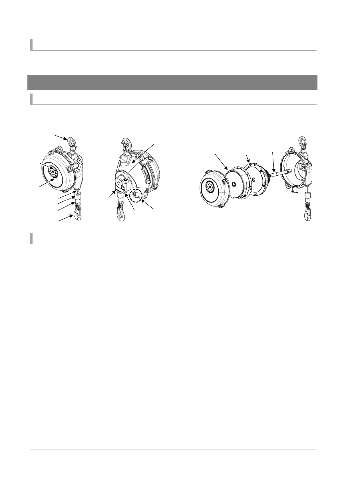
4-1 Components
Note: The shapes and the number of springs differ according to the models
4-1-1 Main equipment
4-2 Operating environment
Installation location: General indoor
Ambient temperature: -10°C to +50°C (no freezing)
Humidity: 85% or less (no condensation)
Atmosphere: Non-explosive, free of flammable or corrosive gas, or dust, water/oil should not
splash directly
Buffer
Top hook
Gauge
Collar
Bottom hook
Cover
Worm
Casing
Wire rope
Wire guide
Drum lock
Spring casing
Drum
Spindle
Exterior
Interior
Spring Balancer Users Manual
6
4-3 Product specifications
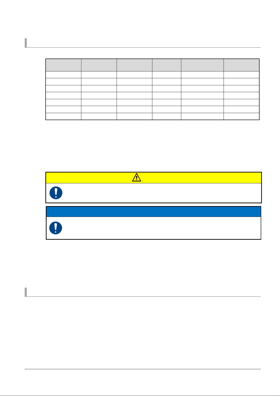
4-3-1 Specifications
Model Capacity
range (kg)
Factory setting
load (kg) Stroke (m)
Wire rope
diameter (φ mm)
Mass (kg)
ELF-15 9 0 to 15 0 12 2 5 4 76 10 0
ELF-22 15 0 to 22 0 18 2 5 4 76 10 2
ELF-30 22 0 to 30 0 26 2 5 4 76 11 0
ELF-40 30 0 to 40 0 35 2 5 4 76 14 5
ELF-50 40 0 to 50 0 45 2 5 4 76 14 9
ELF-60 50 0 to 60 0 55 2 5 4 76 17 1
ELF-70 60 0 to 70 0 65 2 5 4 76 18 0
4-3-2 Fall-arrest device
If the spring is ruptured, this device prevents the tool (equipment) attached to the bottom hook from
falling across the entire stroke If the spring is ruptured, the safety pin is activated from the spring
casing and interferes (collides) with the pin installed on the spring casing, stopping the rotation of the
drum
For the method of releasing the activated fall-arrest device, refer to “7-2 Releasing the fall-arrest
device”
CAUTION
he fall-arrest device is not designed to prevent tools (equipment) from falling.
Before using the balancer, be sure to check that the total mass (weight) of the tool
(equipment) and the accessories is within the capacity range of the balancer.
NOTICE
If the spring tension is set lower than the minimum capacity, the fall-arrest device will
be activated and prevent the vertical movement of the tool (equipment). (See “5-2-2
Installation of tools (equipment) and adjustment of the spring tension”.)
4-3-3 Drum lock device
You can lock the drum by setting the drum lock device (See “6-3 Operation method of the drum lock” )
The drum lock is used to remove the tool (equipment) attached to the bottom hook or to replace the
wire rope or the wire guide (See “6-4-1 Method of removing the tool (equipment)” )
4-4 Applicable standards
Machinery Directive 2006/42/EC
EN ISO 12100: Safety of machinery General principles for design Risk assessment and risk reduction
Note: Only the standard specification of this product complies with the standards If the product is used
in combination with non-standard parts or modified by the customer, the standards may no
longer be complied with Please note this in advance
Spring Balancer Users Manual
7
5. Installation
WARNING
Install the balancer correctly in accordance with the descriptions in this manual.
Incorrect installation may cause an injury, property damage, or damage to the
balancer.
Be sure to attach an auxiliary wire rope or chain to the balancer to protect
workers in case the top hook or the support member (metal hanger) for the
balancer should be damaged.
CAUTION
he installation should be performed by a maintenance operator who has developed
sufficient knowledge and operating skill for the balancer.
5-1 Preparation and checks before installation
5-1-1 ools and equipment for installation
All of the following items must be prepared by the customer
Auxiliary wire rope or chain
Support members (metal hangers)
5-1-2 Check of installation location
Before installing the product, check that the installation location does not have any of the following
problems
1 Check that the support members have a sufficient strength
2 Ensure that sufficient space for performing maintenance, including the adjustment of the spring
tension, is available on a side of the main equipment
3 Ensure that adequate work space is available around the main equipment
4 Check that the installation location has the installation environment described in “4-2 Operating
environment”
5 If a trolley is used, attach a carabiner
6 Check that there are no sharp edges in the installation location
Spring Balancer Users Manual
8
5-2 Installation procedures
5-2-1 Installation of the Spring Balancer
CAUTION
Do not fix the top hook. Using the product with the top hook fixed may cause
damage or a fall.
NOTICE
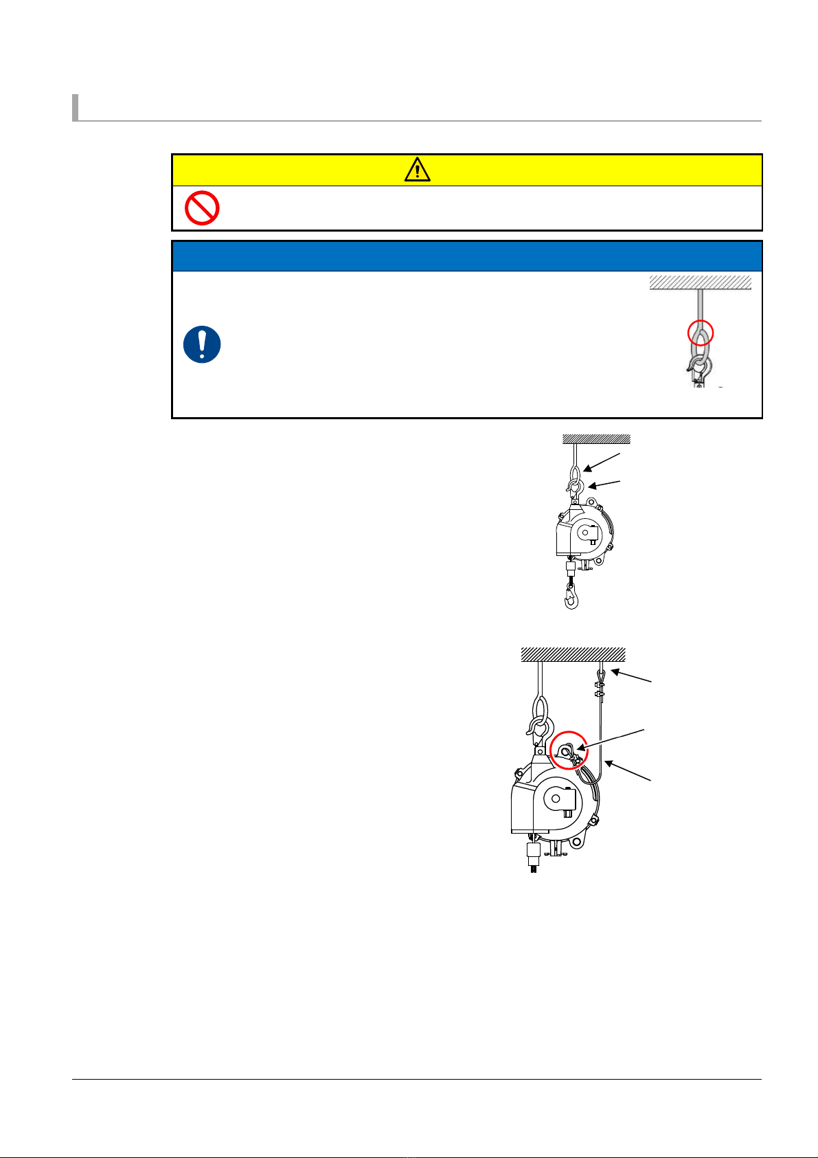
Use a support member (metal hanger) with no opening
as shown in the figure on the right, so that the balancer
does not come off while in motion.
Attach the support member such that the balancer does
not collide with its surroundings.
When installing multiple balancers alongside, place
them at different heights so that they do not collide with
each other.
1
Prepare a support member (metal hanger) with a
sufficient strength Attach the top hook of the
balancer directly to the support member (metal
hanger)
2
Check that the top hook latch is closed
3
Ensure that the balancer moves freely
4
Prepare an auxiliary wire rope or chain that has
a strength at least 10 times greater than the
maximum capacity of the balancer
5
As shown in the figure on the right, attach an
end of the auxiliary wire rope or chain to a
support member (metal hanger) different from
the support member (metal hanger) to which
the top hook has been attached Attach the
other end of the auxiliary wire rope or chain to
the main equipment of the balancer
Support members
(metal hangers)
Top hook
Note: The support member
(metal hanger) and the tool
(equipment) in the figure
are indicated for reference
Installation of the
auxiliary wire rope to
the main equipment
Support member
for the auxiliary
wire rope
Auxiliary wire rope
Note: The auxiliary wire rope
and the support member
in the figure are
indicated for reference
Spring Balancer Users Manual
9
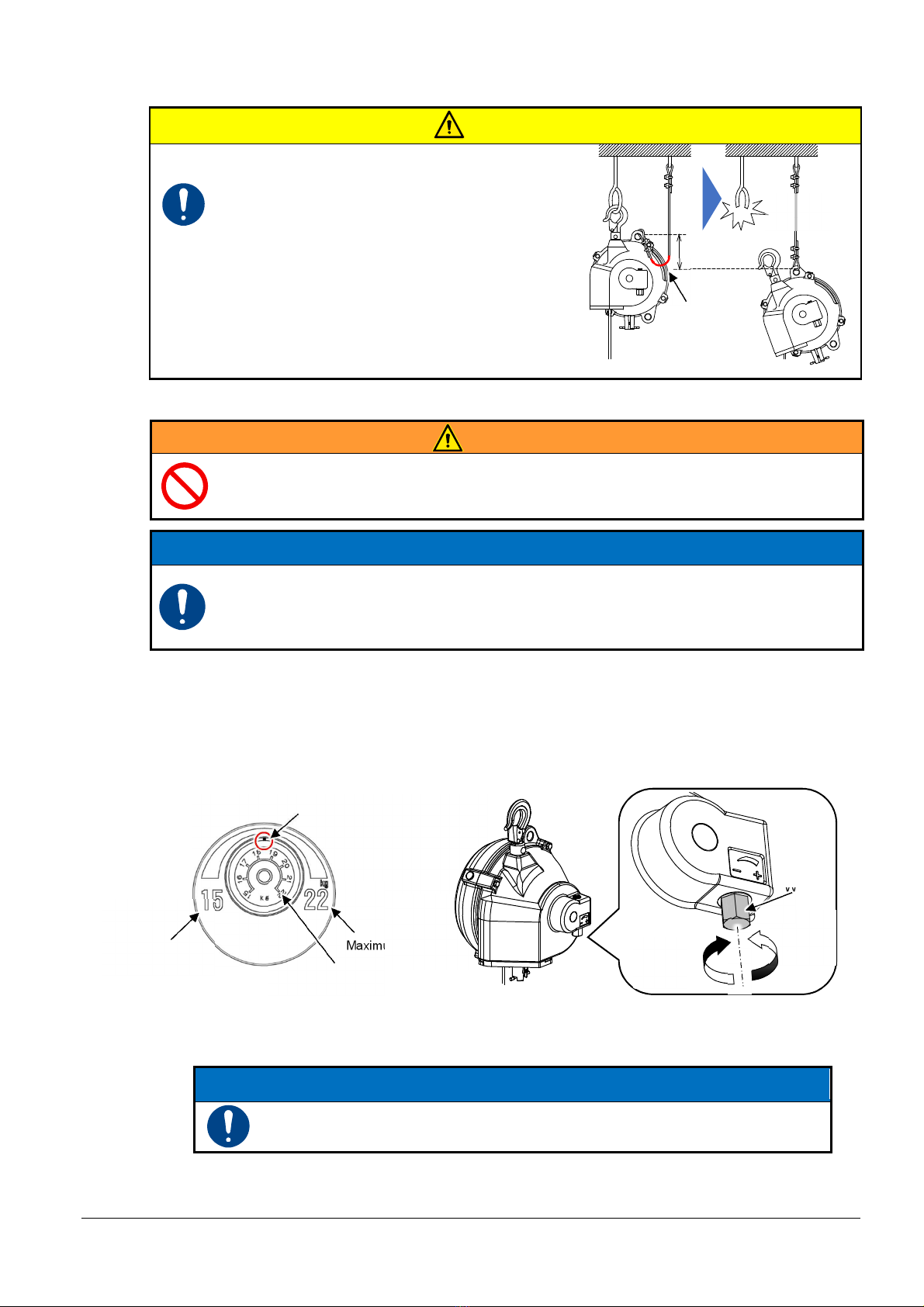
CAUTION
Loosen the auxiliary wire rope or chain to
allow the balancer to move freely.
he slack must be such that the balancer
stops within 100 mm if the top hook or
the support member (metal hanger) for
the balancer are damaged and the
balancer falls.
5-2-2 Installation of tools (equipment) and adjustment of the spring tension
WARNING
Do not pull out the wire rope when the balancer is not loaded. If the wire rope is
released by mistake while being pulled out without a load, it may quickly be wound
up, causing an injury.
NOTICE
If the spring tension is set higher than the maximum capacity, not only will the
specified stroke not be obtained, but the life of the spring will also be reduced. Also,
if the spring tension is set lower than the minimum capacity, the fall-arrest device will
be activated and prevent the vertical movement of the tool (equipment).
1
Check whether the total mass (weight) of the tool (equipment) and the accessories is within the
capacity range of the balancer
2
While checking the gauge, turn the worm with a spanner or the like to adjust the spring tension
so that the tension is suitable for the mass (weight) of the tool
The tension will increase if you turn the worm in the “+” direction (clockwise)
The tension will decrease if you turn the worm in the “-” direction (counterclockwise)
3
Lift the tool (equipment) and attach it to the bottom hook of the balancer
Do not pull out the wire rope
4
After attaching the tool (equipment), perform readjustment and ensure that balance is achieved
NOTICE
If the spring tension is too strong, the main equipment of the balancer or
the wire rope may be damaged.
Capacity indication point
(18 5 kg for this example)
Maximum capacity
Minimum capacity
Gauge
Slack
Within
100 mm
Damaged
and falls
“+”
Increase
tension
Worm
“-”
Decrease
tension

Spring Balancer Users Manual
10
5-3 Post-installation checks
5-3-1 Checking the working range (stroke)
1 Ensure that work can be performed within the range of the stroke
For the stroke of each product, see “4-3-1 Specifications”
2 If the range of the stroke is insufficient, lower the
installation height of the balancer or use an appropriate
sling between the bottom hook and the tool (equipment)
6. Usage
6-1 Pre-operation inspections and checks
WARNING
If any abnormality is found as a result of inspection, do not use the balancer.
If any loose bolts or screws are found in the inspections, retighten the bolts and
screws.
When you notice any wear, deterioration or deformation of the parts, contact us or
your dealer.
Inspect and check the following items before starting the operation:
Check of the surroundings
1 Ensure that there is no trash or unnecessary equipment around the balancer or in the work
space
2 If there is any obstacle and the like that cannot be removed, contact the person in charge of the
work
Inspection of the support member (metal hanger)
1 Check that the support member (metal hanger) is not worn
2 If any wear is found, immediately stop the operation
NOTICE
Do not extend the wire rope beyond the stroke. Doing
so may damage the balancer.
Note: The auxiliary wire rope, the support member, and the
tool (equipment) in the figure are indicated for
reference
Stroke
Note: The support member
(metal hanger) in the
figure is indicated for
reference
Wear

Spring Balancer Users Manual
11
Check of the main equipment of the balancer
For the main equipment of the balancer, perform the following
inspections and checks
1
Check that the top and bottom hooks are not worn
and can rotate smoothly
2
Check that the latches of the top and bottom hooks
are not deformed and do not come off the hooks
3
Check that the wire rope is not worn (Note:
particular attention should be paid to wire breakage
and the base of terminal locks)
4
Check that the buffer is not worn or cracked
5
Check for significant wear or cracks in the wire
guide Check that the mounting screws are not
loose
6
Check that the case is not worn, the mounting bolts
are not loose, and air is not leaking
7
Check that the auxiliary wire rope (or chain) is not
worn and the mounting bolts are not loose
8
Check that the pin and the safety pin have not
dropped off
9
Check the E-type retaining ring is not removed
10
Check that the screws and the bolts in various
parts are not loose
6-2 Precautions for use
WARNING
Do not move directly under the tool (equipment) suspended from the balancer.
Do not perform any modification of the balancer.
Do not remove tools (equipment) with the wire rope pulled out. he wire rope may
be quickly wound up, causing an injury.
CAUTION
Be sure to use the product within the capacity range. (Refer to the capacity range in
“4-3-1 Specifications”)
NOTICE
Do not extend the wire rope further than its stroke.
Do not extend the wire rope in an oblique direction.
Adjust the spring tension before the operation.
Remove the tool (equipment) while lifting it and with the wire rope completely wound inside the drum
Note: The support member (metal hanger)
and the auxiliary wire rope in the figure
are indicated for reference
1
1
8
5
3
2
2
7
9
6
Spring Balancer Users Manual
12
6-3 Operation method of the drum lock
Operate the drum lock according to the figure below
6-3-1 Activation of the drum lock
WARNING
Do not remove the tool (equipment) attached to the bottom hook until it is
confirmed that the drum is securely locked.
If the drum is locked inadequately, the drum lock may be released during the
work. hen, the wire rope may be quickly wound up, causing an injury.
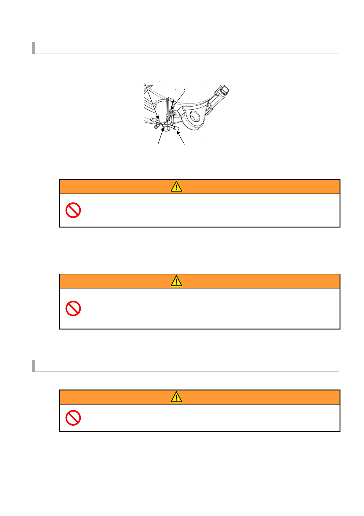
1
Remove the spring pin from the release position and move it to the lock position
2
Move the tool (equipment) up and down to check that the drum is securely locked
6-3-2 Release of the drum lock
WARNING
Do not release the drum lock when the balancer is not loaded or after the tool
(equipment) is replaced with one with a different mass (weight). If the drum lock
is released in such situations, the wire rope may be quickly wound up as soon as
the lock is released, the tool may fall, or an injury may be caused. Attach the tool
and adjust the spring tension before releasing the drum lock.
1
If the tool has been removed, be sure to attach the removed tool
2
Remove the spring pin from the lock position and move it to the release position
6-4 Replacement of the tools (equipment)
6-4-1 Method of removing the tool (equipment)
WARNING
Do not move directly under the tool (equipment) suspended from the balancer.
Do not remove tools (equipment) with the wire rope pulled out. he wire rope may
be quickly wound up, causing an injury.
1
Confirm that the tool (equipment) can be moved up and down
2
Lift the tool and wind the wire rope completely inside the drum
3
Remove the tool (equipment)
Lock position
(deeper slot)
Spring pin
Pin
Release position
(shallower slot)
Spring Balancer Users Manual
13
6-4-2 Method of attaching the tool (equipment)
WARNING
Do not move directly under the tool (equipment) suspended from the balancer.
CAUTION
Be sure to use the product within the capacity range. (Refer to the capacity range in
“4-3-1 Specifications”)
NOTICE
Adjust the spring tension before the operation.
1 Check whether the total mass (weight) of the tool (equipment) and the accessories is within the
capacity range of the balancer
2 Install the tool (equipment) and adjust the spring tension in accordance with “0 Installation of
tools (equipment) and adjustment of the spring tension”
6-4-3 Replacement of the tool (equipment) using the drum lock
WARNING
Do not move directly under the tool (equipment) suspended from the balancer.
Do not replace the tool with one with a different mass.
Do not remove the tool before checking that the drum is securely locked by
moving the tool (equipment) up and down. If the drum is locked inadequately, the
drum lock may be released during the work. hen, the wire rope may be quickly
wound up, causing an injury.
CAUTION
Be sure to use the product within the capacity range. (Refer to the capacity range in
“4-3-1 Specifications”)
NOTICE
Adjust the spring tension before the operation.
1 Confirm that the tool (equipment) can be moved up and down
2 Lock the drum within the range of the stroke according to “6-3 Operation method of the drum
lock”, and then remove the tool
3 Confirm that the mass of the tools is identical, and attach the tool (equipment) according to “0
Installation of tools (equipment) and adjustment of the spring tension”
6-5 Periodical inspections
Perform an inspection at least once per month
For the method of the periodical inspections, download “Repair Manual” from our website and refer to
“2-2 Periodical inspections” in “Repair Manual”
http://www endo-kogyo co jp
If the product is used in an unfavorable environment or used frequently, reduce the interval between
the inspections
Spring Balancer Users Manual
14
7. roubleshooting
7-1 Countermeasures?
WARNING
Do not remove the tool (equipment) attached to the wire rope end until the cause of
the failure is identified. If the tool (equipment) is removed, the wire rope may be
quickly wound up, causing an injury.
CAUTION
If you notice anything unusual, stop the operation immediately. After checking the
items listed in the table below, appropriate measures should be taken by a
maintenance operator who has developed sufficient knowledge and operating
skill for the balancer.
If the situation does not relate to any of the listed items in the table below, contact
us or your dealer.
Failure Reason Measure
The wire rope cannot
be pulled out or
wound
The drum lock is activated Release the drum lock
See “6-3 Operation method of the drum
lock”
The spring tension is
increased too much and the
spring has been tightly
wound
Decrease the spring tension
See “0 Installation of tools (equipment)
and adjustment of the spring tension”
The spring tension is
decreased too much and the
fall-arrest device has been
activated
Release the fall-arrest device
See “7-2 Releasing the fall-arrest
device”
The wire rope came off the
groove on the drum and is
caught between the casing
and the drum
Return the wire rope to the groove on
the drum
See “2-6 Countermeasures when the
wire rope is caught between the drum
and the casing” in “Repair Manual”
The spring has been
ruptured
Replace the spring
See “2-4 Replacement of the spring” in
“Repair Manual”
7-2 Releasing the fall-arrest device
If the fall-arrest device is activated, for example, when the spring tension is reduced too much, release
the fall-arrest device with the following procedure
1 Move the tool (equipment) up and down manually
The tool can be moved up and down within approximately 70 mm to 160 mm
2 If the tool descends after being lifted up by hand and then released, turn the worm in the “+”
direction (clockwise) until the tool starts ascending At this time, never remove the tool
3 Confirm that the tool can be moved up and down, and that the fall-arrest device is released
4 If the fall-arrest device cannot be released with the procedure above, the spring is ruptured
Replace the spring according to “2-4 Replacement of the spring” in “Repair Manual”

Spring Balancer Users Manual
15
8. Dimensional Drawing
Outline drawing (Table of external dimensions)
Model
Dimension (mm)
A B C D E F G
MIN
MAX
ELF-15, 22, 30 469
2969 213 φ230 18 18 φ3 2
φ3 2
ELF-40, 50 487
2987 228 φ250 18 18 φ3 2
φ3 2
ELF-60, 70 487
2987 258 φ250 18 18 φ3 2
φ3 2
9. Consumables and Special Accessories
The consumables include the following parts If any of these parts are broken or any wear or damage is
found, replace them
Spring
Wire rope
Wire guide
Drum
Note: For the replacement of the consumables and other parts, download “Repair Manual” from our
website or contact us or your dealer
For special accessories of the Spring Balancer, check in the catalog linked on our website
Our website: http://www endo-kogyo co jp/
10. Disposal of Product
When disposing of the product, follow the local regulations of the area where the product to be
disposed, and dispose it as industrial waste

遠藤工業株式会社
〒959-1261 新潟県燕市秋葉町 3 丁目 14 番 7 号
http://www.endo-kogyo.co.jp
本社営業部
〒959-1261 新潟県燕市秋葉町 3 丁目 14 番 7 号
TEL:
0256-62-5133 FAX: 0256-62-5772
エコファクトリー
〒959-1276 新潟県燕市小池 5181 番地 1
TEL:
0256-63-9306 FAX: 0256-63-4393
東京営業部
〒101-0042 東京都千代田区神田東松下町 12 番 2 号 JBSL 神田ビル 2F
TEL:
03-5295-3711 FAX: 03-5295-3717
名古屋営業所
〒460-0011 愛知県名古屋市中区大須 1 丁目 7 番 14 号パーク IM ビル 3F
TEL:
052-253-6231 FAX: 052-253-6240
大阪営業部
〒556-0021 大阪府大阪市浪速区幸町 2 丁目 3 番 14 号ダイトービル 3F
TEL:
06-6568-1571 FAX: 06-6568-1573
九州営業所
〒812-0013 福岡県福岡市博多区博多駅東 3 丁目 11 番 15 号文喜ビル 3F
TEL:
092-412-5281 FAX: 092-412-5280
サービス営業グループ
〒959-1261 新潟県燕市秋葉町 3 丁目 14 番 7 号
TEL:
0256-64-4786 FAX: 0256-62-5772
E-mail:[email protected]
ENDO KOGYO CO., LTD.
3-14-7, Akiba cho, Tsubame, Niigata 959-1261, Japan
http://www.endo-kogyo.co.jp/ TEL: 81-256-62-5133
本書、ならびに本製品の仕様は、改善のために予告なしに変更することがあります。
本書の内容の無断転載を禁止します。
This manual and the specifications of this product are subject to change for
improvement without advance notice
It is strictly prohibited to reprint or copy any information contained in this manual

Repair Manual
Spring Balancer
ELF-15 ELF-40 ELF-70
ELF-22 ELF-50
ELF-30 ELF-60
BMR-0015
Issued in December 2022
For safe and correct operation of the product, please be sure to read this manual and fully
understand its content before use
After reading, keep the manual safe so that you can find and use it readily
In case of resale or transfer of ownership of this product, make sure to transfer the manual
to the new owner

Spring Balancer Repair Manual
1
Introduction
Thank you very much for purchasing the Spring Balancer To prevent any trouble and obtain the best
performance, please be sure to read this Repair Manual and the separate Users Manual, and fully
understand their content
otation in this manual
Hazard levels
This product is designed with ultimate priority on the safety of operators However, due to the
nature of the system, there are risks that cannot be removed
In this manual, the level of significance and risk is defined and indicated in three stages:
“WARNING”, “CAUTION”, and “NOTICE” Thoroughly read and fully understand the indicated
items before operating the product and performing maintenance procedures The indications for
“WARNING”, “CAUTION”, and “NOTICE” are in order of risk significance (WARNING > CAUTION
> NOTICE) Their details are described below
WARNING
A situation that, if mishandled, may cause death or serious disability
CAUTION
A situation that, if mishandled, may cause minor or moderate injury
NOTICE
A situation that, if mishandled, may cause property damage
The extent of the problem described above (disability, injury, and property damage) is defined as
follows
Serious disability
: Loss of eyesight, wound, burn (high-temperature or low-temperature),
electric shock, bone fracture, poisoning, and other injuries that leave
aftereffects and that require hospitalization or long-term outpatient treatment
Moderate injury
: Burn, electric shock, bone fracture, and other injuries that do not require
hospitalization or long-term outpatient treatment
Minor injury
: Scratch, bruise, laceration, and other injuries that have a minor impact on
health
Property damage
: Extended damage to buildings, household articles, and injury to domestic
animals or pets
Other than WARNING, CAUTION, and NOTICE described above, matters important to workers
are indicated using the following format
REMINDER
Describes important details to be remembered for the operation

Spring Balancer Repair Manual
2
Symbols
This Users Manual uses the following symbols to simply provide information in addition to the
indications above
Indicates a PROHIBITED action
that must not be performed
Indicates potential property damage
or a danger that may inflict bodily
injury
Indicates a REQUIRED action that
must be performed
Indicates that it is necessary to
thoroughly read the manual and the
relevant documents
Illustrations
This manual covers multiple models of the Spring Balancer If their functions and details of
operations are identical and can be correctly described in the same way, illustrations are provided
taking a specific model as an example Therefore, please note that the illustrations may be
different from the actual equipment
This manual suits for next models
6
Table of contents
Other Endo Wheel Balancer manuals


