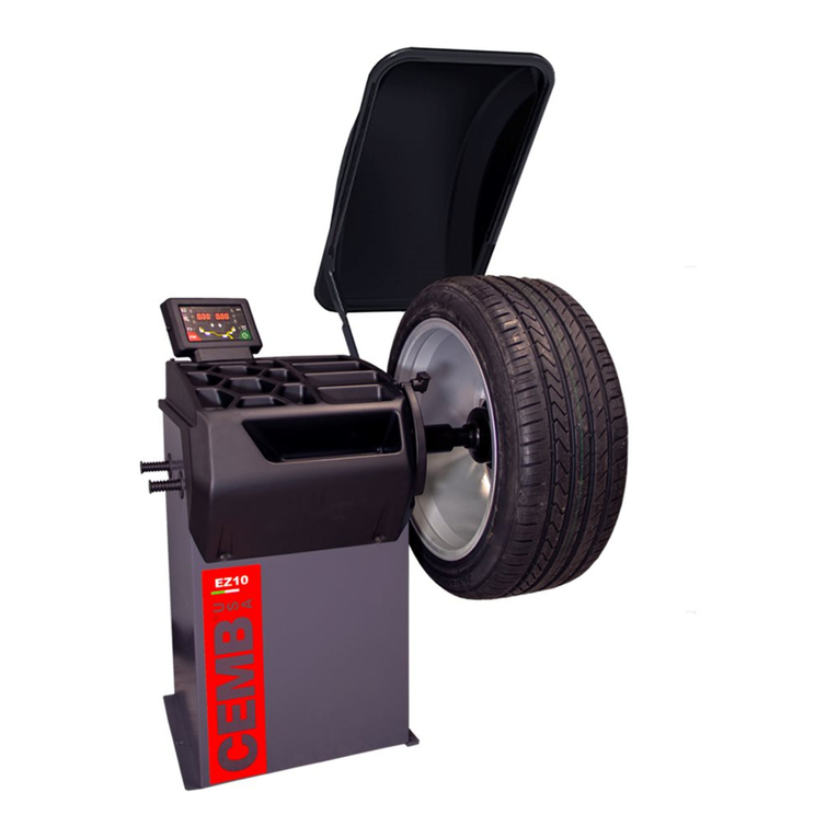
CEMB EZ1 User manual

I 1213 - 02/16 - Ver. 01
Use and maintenance manual
EN
ENGLISH
General Index
1. FOREWORD 3
1.1 GENERAL 3
1.2 PURPOSE OF THE MANUAL 3
1.3 WHERE AND HOW TO KEEP THE MANUAL 3
1.4 MANUAL UPGRADES 3
1.5 COLLABORATION WITH USERS 4
1.6 MANUFACTURER 4
1.7 MANUFACTURER'S RESPONSIBILITY AND WARRANTY 4
1.7.1 Terms of warranty 4
1.8 TECHNICALASSISTANCE SERVICE 5
1.9 COPYRIGHT 5
2. MACHINE DESCRIPTION 6
2.1 PURPOSE 6
2.2 TECHNICAL SPECIFICATIONS 6
2.3 DIMENSIONS 6
3. STARTING 7
4. CONTROL PANEL 8
5. USE OF THE WHEEL BALANCER 9
5.1 DIMENSIONS SETTING WHEEL 9
5.1.1 Standard wheel 9
5.1.2 Wheels with internal correction to rim 9
5.2 MEASUREMENT RESULT 9
5.3 SPLIT FUNCTION (hidden weight) 10
5.4 UNBALANCE OPTIMISATION 10
6. SETUP 11
6.1 MENU 11
6.1.1 Self-diagnostics 12
6.1.2 Calibration 12
6.1.3 Setting start speed measurement 12
7. DIAGNOSTICS 13
7.1 INCONSISTENT UNBALANCE READINGS 13
7.2 ALARM SIGNAL 13
8. MAINTENANCE 15
8.1 GENERAL 15
8.1.1 Introductory notes 15
8.1.2 Safety rules 15

3
Ver. 02-2016
ENGLISH
Use and maintenance manual
WARNING
ThIs mANuAl Is AN INTeGRAl pART of The INsTAllATIoN
mANuAl WhIch should be coNsulTed coNceRNING sTARTING
ANd usING The mAchINe sAfely.
ReAd cARefully befoRe coNTINuING.
1.1 GENERAL
The machine has been constructed in conformity with the
current EC Directives and the technical standards imple-
menting the requirements, as stated in the declaration
of conformity issued by the manufacturer and attached
to the manual.
This publication, hereinafter simply referred to as ‘man-
ual’, contains all the information required to safely use
and service the machine referred to in the Declaration of
Conformity.
This appliance, hereinafter is generically referred to as
‘machine’.
Themanualaddressesoperatorsinstructedontheprecau-
tions to take in relation to the presence of electric current
and moving devices.
This publication is intended for all ‘users’ who as far as
within their competence need to and/or are obliged to
give instructions to others or operate on the machine
themselves.
These persons can be identified as follows:
- operators directly involved in transporting, storing,
installing, using and servicing the machine from when
it is put on the market until when it is scrapped;
- direct private users.
The original Italian text of this publication constitutes the
only reference to resolve any interpretation controversies
related to the translation into the European Community
languages.
This publication forms an integral part of the machine
and must therefore be kept for future reference until final
dismantling and scrapping of the machine.
1. Foreword
1.2 PURPOSE OF THE MANUAL
This manual, and the installation manual, contains the
instructions required to use the machine safely and carry
out routine maintenance work.
Any calibrations, adjustments and extraordinary mainte-
nance operations are not considered in this document as
they may only be performed by the service engineer who
must work on the machine according to the technical and
rated characteristics for which it was built.
Though it is fundamental to read this manual, it cannot
replace skilled technical staff who must be adequately
trained beforehand.
The foreseen use and configurations of the machine are
theonlyones allowedbythemanufacturer;do not attempt
to use the machine in a different way.
Anyotheruseor configuration must be agreed in advance
with the manufacturer in writing and in this case an annex
will be attached to this manual.
For use, the user must also comply with the specific
workplace legislation in force in the country where the
machine is installed.
The manual also refers to laws, directives, etc., that the
user must know and consult in order to accomplish the
goals that the manual sets out to achieve.
1.3 WHERE AND HOW TO KEEP THE
MANUAL
This manual (and relative attachments) must be kept in
a safe and dry place and must always be available for
consultation.
Make a copy and keep it in the archive.
When exchanging information with the manufacturer or
the technical assistance staff authorised by the former,
quote the rating plate information and the serial number
of the machine.
This manual must be kept for the entire lifetime of the
machine, and if necessary (e.g.: damage making all or
some of it illegible, etc.) the user must request another
copy exclusively from the manufacturer, quoting the pub-
lication code indicated on the cover.
1.4 MANUAL UPGRADES
Thismanualis an integral part ofthe machine and reflects
thestate of the art at the moment it was put on the market.
The publication complies with the directives in force on
that date; the manual cannot be considered inadequate
as a result of regulatory updates or modifications to the
Introduction

4
Ver. 02-2016
ENGLISH
Use and maintenance manual
Introduction
machine.
Anymanualupgradesthat the manufacturer may seefitto
send to users will become an integral part of the manual
and must be kept together with it.
1.5 COLLABORATION WITH USERS
The manufacturer will be pleased to provide its custom-
ers with any further information they may require and will
consider proposals for improving this manual in order to
more fully satisfy the requirements it was written for.
In case of transfer of ownership of the machine,
which must always be accompanied by the use and
maintenance manual, the original user must inform
the manufacturer of the name and address of the
new user in order to allow it to send the new user
any communications and/or updates deemed to be
indispensable.
This publication is the property of the Manufacturer
andmaynotbefullyorpartlyreproducedwithoutprior
written agreement.
1.6 MANUFACTURER
The machine identification data is indicated on the plate
mounted on the machine.
The plate below is shown for the sake of example.
1.7 MANUFACTURER'S RESPONSIBILITY
AND WARRANTY
In order to make use of the manufacturer's warranty, the
usermustscrupulouslyobservetheprecautionscontained
in the manual, in particular he must:
- never exceed the limits of use of the machine;
- always constantly and carefully clean and service the
machine;
- have the machine used by people of proven capacity
and attitude, adequately trained for the purpose.
The manufacturer declines all direct and indirect liability
caused by:
- useofthemachineinadifferentwayfromthatindicated
in this manual
- use of the machine by people who have not read and
fully understood the contents of this manual;
- use in breach of specific regulations in force in the
country of installation;
- modifications made to the machine, software and op-
erating logic, unless authorised by the manufacturer
in writing;
- unauthorised repairs;
- exceptional events.
Transfer of the machine to a third party must also include
this manual; failure to include the manual automatically
invalidates all the rights of the purchaser, including the
terms of warranty, where applicable.
Ifthemachineistransferredtoathirdpartyinacountrywith
a different language from the one written in this manual,
the original user shall provide a faithful translation of this
manual in the language of country in which the machine
will operate.
1.7.1 Terms of warranty
The Manufacturer guarantees the machines it manufac-
turers against all manufacturing or assembly faults for 12
(twelve) months from the date of collection or delivery.
TheManufacturerundertakestoreplaceorrepair anypart
which it deems to be faulty free of charge at its factory,
carriage paid.
If a Manufacturer's repairman (or a person authorised by
the same) is required to work at the user's facilities, the
relative travel expenses and board and lodging shall be
charged to the user.
The free supply of parts under warranty is always subject
to the faulty part being inspected by the manufacturer (or
a person authorised by the same).
The warranty is not extended following repairs or other
work done to the machine.
The warranty does not cover damage to the machine
deriving from:
- transport;
- neglect;
- improper use and/or use not in compliance with the
instructions in the operating manual
- incorrect electrical connections.
The warranty is invalidated in case of:
- repairs made by people who were not authorised by
the manufacturer;
- modifications that were not authorised by the manu-
facturer;
- use of parts and/or equipment that were not supplied
or approved by the manufacturer;
- removal or alteration of the machine identification
plate.

5
Ver. 02-2016
ENGLISH
Use and maintenance manual
Introduction
1.8 TECHNICAL ASSISTANCE SERVICE
Foranytechnicalserviceoperation,contactthemanufacturer
directlyoranauthoriseddealer always quoting the model,
the version and the serial number of the machine.
1.9 COPYRIGHT
The information contained in this manual may not be
disclosed to third parties. Partial or total duplication, un-
less authorised by the Manufacturer in writing, through
photocopying, duplication or other systems, including
electronic acquisition, is breach of copyright and can lead
to prosecution.

6
Ver. 02-2016
2
4
1
ENGLISH
Use and maintenance manual
Machine description
2.1 PURPOSE
Itisasimpleandextremelycompactwheelbalancerusable
everywhere: on a garage wall, installed on a lift, on a tire
changer, on a workbench or in a van.
The measuring quality is the same of high-end balancers.
It is used to balance the wheels of cars, vans, 4-WD,
motorcycles and scooters weighing less than 75 Kg.
Itcanbeoperatedinthetemperaturerangeof0°to+45°C.
Do not mount anything other than motorbike, car or truck
tyres on the wheel balancer.
2.2 TECHNICAL SPECIFICATIONS
The following data refers to the balancer in its standard
configuration.
Single phase power supply 115-230V AC or 12-24V DC
(see rating plate)
Protection class IP 54
Cycle time per wheel 4.7 s (5 3/4"x14") 15 kg
Balancing speed 100 min-1
Measurement uncertainty 1 g
Average noise < 70 dB(A)
Rim width setting range 1.5" ÷ 20" or 40 ÷ 510 mm
Diameter setting range
10" ÷ 30" or 265 ÷ 765 mm
Maximum wheel weight
< 75 kg
Machine weight
~ 35 kg
2.3 DIMENSIONS
2. Machine description
1. CONTROL PANEL
2. LOCK NUT

7
Ver. 02-2016
ENGLISH
Use and maintenance manual
Starting
3. Starting
WARNING
BefoRe sWItchING oN the mAchINe, mAke suRe thAt All the
coNNectIoNs descRIBed IN the INstAllAtIoN chApteR
hAve BeeN mAde coRRectly.
the folloWING opeRAtIoNs INvolve ApoteNtIAl RIsk foR
the opeRAtoR, GIveN the pReseNce of voltAGe oN the
equIpmeNt. the peRsoNAl pRotectIve equIpmeNt de-
scRIBed IN the INstAllAtIoN mANuAl must Be WoRN ANd
WoRk must Be doNe WIth due cARe ANd AtteNtIoN.
opeRAtIoNs mAy oNly Be peRfoRmed By A
specIAlIsed techNIcIAN.
The standard version can be fixed to a wall or to any
support that grants proper rigidity.
Tire changer installing devices as well as tilting back van
adapters are supplied as option.
Other installation features can be provided upon request.
Beforepoweringthemachine,carryoutthefollowingchecks:
1. Check that the balancing machine is securely fastened.
2. Make sure that all the parts of the balancer are cor-
rectly connected and fixed.
3. Make sure that the parameters (voltage and frequency)
ofthemainspowersupplyarecompatiblewiththose
indicated on the rating plate of the balancer.
4. Make sure the power cable is correctly connected.
5. Make sure the machine shaft and flange hole are
clean.
cAutIoN
ANy tRAces of dIRt mAy Affect BAlANcING AccuRAcy.
A lock INcoRRect INto plAce of WoRk INvolves the BAlANcING
mAchINe mAlfuNctIoN.
6. To switch on the balancer press the switch on the
lower side of the machine.
7. Positionthewheelontheterminalwiththeinnerpart
facing the balancer.
8At this point, you can read the tyre measurements
and perform balancing.

8
Ver. 02-2016
1 2
7
4
3
6
8 9
10
12
14
11
4
5
7
13
ENGLISH
Use and maintenance manual
Control panel
1. Inner side UNBALANCE VALUE digital indicator
2. Outer side UNBALANCE VALUE digital indicator
3. Inner side UNBALANCE POSITION indicator
4. Outer side UNBALANCE POSITION indicator
5. DISTANCE setting
6. DIAMETER setting
7. WIDTH setting
8. INNER SIDE correction position selection (selects and views the position for applying
the correction weight)
9. STATIC and OUTER SIDE correction position selection (selects and views the position
for applying the correction weight)
10. SPLIT (hidden weight)
11. Unbalance reading below the threshold
12. Confirm MENU selection
13. HOME
14. FUNCTIONS menu
cAutIoN
pRess the ButtoNs WIth youR fINGeRs.
NeveR use the couNteRWeIGht GRIppeRs oR otheR poINted oBjects!
4. Control panel

9
Ver. 02-2016
ab
d
b
a
ENGLISH
Use and maintenance manual
5. Use of the wheel balancer
5.1 DIMENSIONS SETTING
WHEEL
5.1.1 Standard wheel
a. Set the DISTANCE “a” between the inner side of the
wheel and the machine.
For this operation use an ordinary tape measure.
b. Set the rated WIDTH, normally indicated on the rim,
or measure the width “b” using the supplied calliper
gauge.
c. Set the rated DIAMETER “d” indicated on the tyre.
5.1.2 Wheels with internal correction to
rim
Select the correction position according to the method
used to apply the weights to the wheels.
For this operation use the two buttons .
Use the gauge to measure the distances according to the
following scheme.
To set dE hold down the button (red button) for 2
seconds,whenanyofthedimensionsappearonthedisplay.
5.2 MEASUREMENT RESULT
Use of the wheel balancer

10
Ver. 02-2016
1
2
1
2
1
2
1
2
ENGLISH
Use and maintenance manual
Move the wheel manually until all the LED’s correspond-
ing to the side light up. The display shows the measured
unbalance.
For unbalance within tolerance 0 (zero); using
values within tolerance can be viewed.
5.3 SPLIT FUNCTION
(hidden weight)
TheSPLITfunctionisusedtopositiontheadhesiveweights
behind the wheel spokes (angle > 18°) so that they are
no longer visible (for alloy rims). Use this function in the
ALU or STATIC mode where the adhesive weight is ap-
plied inside the rim.
Enter the wheel dimensions and perform a manual spin.
a. Turn the wheel to the outer side unbalance correction
position.
b. Move one of the spokes to 12 o'clock (e.g.: 1) and
press
c. Following the direction of rotation indicated by the
position LED's, move spoke 2 to12 o'clock and press
.The value to use for correction in position 2 is
displayed.
d. Move spoke 1 to the correction position as indicated
by the position LED's
To return to the normal unbalance indication press any
button.
INfoRmATIoN
The spoke-to-spoke distance must be a minimum of 18°
and a maximum of 120° (if not, errors 24, 25 or 26
appear). Spokes with irregular or inconstant angles
can be compensated.
5.4 UNBALANCE OPTIMISATION
This operation is performed to reduce the static unba-
lance of the wheel.
It is suitable for static unbalance values in excess of 30
grams.
a. Ifnounbalancewasmeasuredbefore,STARTappears
on the display. Otherwise go to step b.
b. Makea referencemarkontheflange andtherim(using
a piece of chalk, for example).
With the aid of a tyre remover, turn the tyre on the rim
by 180°.
Retthewheelinsuchawaythatthereferencemarks
ontherimandtheangecoincide.
c. RH display: percentage reduction value
LH display: actual static unbalance value which can be
reduced by rotation
d. Markthe two positions of the rim and tyre, and turn the
tyre on the rim until the positions coincide to achieve
the optimisation shown on the display
To cancel optimisation at any time, press .
TYRE
POSITION
RIM POSITION
Use of the wheel balancer
Perform a
manual spin
Perform a
manual spin

11
Ver. 02-2016
ENGLISH
Use and maintenance manual
6. Setup
6.1 MENU
This is used to personalise some balancer functions and to perform calibrations.
To access this section, press the FUNCTIONS MENU button.
See chapter on UNBALANCE OPTIMIZATION
RETURNS TO MEASUREMENT SCREEN
See AUTO-DIAGNOSTICS
See CALIBRATION
Setup
approximates 1-5-10 g
.10 -.25 - .50 oz
default 5g/.25 oz
tolerance 5-10 g
.40 - .50 oz
default 5g - .40 oz
diameter unit of
measure mm/inch
width unit of
measure mm/inch
setting start
speed
measurement
unbalance unit
of measure g/.oz

12
Ver. 02-2016
ENGLISH
Use and maintenance manual
6.1.1 Self-diagnostics
The machine can perform self-diagnostics to check the
LED's on the control panel and make sure the encoder
reads correctly.
To perform this operation, view the SETUP menu.
In the self-diagnostics sequence, all the LED's on the panel
light up for a few seconds in order to check operation. When
theLED'sgoout,themachineautomaticallymovesontothe
encoder reading phase. When the wheel is turned manually
(forwards and backwards), the display shows its exact posi-
tion. The value lies between 0 (zero) and 255.
6.1.2 Calibration
To calibrate the machine, proceed as follows:
▪Fit an average size wheel with a metal rim on the shaft.
Example: 6” x 15” (± 1”).
▪Setthewheelmeasurementsasdescribedinparagraph
SETTING WHEEL DIMENSIONS.
cAuTIoN
seTTING INcoRRecT dImeNsIoNs Would meAN ThAT The mAchINe
Is NoT coRRecTly cAlIbRATed, TheRefoRe, All subsequeNT
meAsuRemeNTs WIll be INcoRRecT uNTIl cAlIbRATIoN Is peR-
foRmed oNce AGAIN WITh The coRRecT dImeNsIoNs.
Display the SETUP menu:
1. Press to view view the CALIBRATION
function.
2. Add a standard weight of 60 g (2.00 oz) to the outer
side, in any position.
.
3. Shift the standard weight from the outside to the
inside keeping the same position.
4. Turn the wheel until the standard weight is at the top
(12 o'clock).
5. End of calibration.
To cancel calibration at any time, press .
6.1.3 Setting start speed measurement
cAuTIoN
ReseRved foR specIAlIzed peRsoNNel
Setthe shutdownspeedofthedisplay,to indicatetheuser
to stop the acceleration of the wheel.
Setting range 100-130 rpm.
Setup
Perform a
manual spin
Perform a
manual spin
Perform a
manual spin

13
Ver. 02-2016
ENGLISH
Use and maintenance manual
7. Diagnostics
7.1 INCONSISTENT UNBALANCE
READINGS
In some cases, when a wheel that has just been balanced
is repositioned on the balancer, the machine can detect
an unbalance.
Thisisnotamachineproblembutisduetofaultymounting
of the wheel on the flange. In other words, when mount-
ing the wheel after initial balancing, it has taken another
position with respect to the balancer shaft axis.
If the wheel has been mounted on the flange with screws,
the screws may not have been tightened correctly (criss-
cross sequence) or the tolerances of the holes drilled in
the wheel may be too large. Small errors, up to 10 grams
(4 oz), are to be considered normal in wheels locked with
the relative cone: The error is normally greater for wheels
locked with screws or studs.
If, after balancing, the wheel is still unbalanced when re-
fitted on the vehicle, this could be due to an unbalanced
brake drum or, very often, the tolerances of the holes
drilled in the rim and drum are too large. In this case,
balancing should be performed using a balancer with the
wheel mounted on the vehicle.
7.2 ALARM SIGNAL
The machine has a self-diagnostics cycle which identi-
fies the most frequent malfunctions during the normal
work cycle.
These malfunctions are processed by the system and
shown on the display.
Diagnostics

14
Ver. 02-2016
ENGLISH
Use and maintenance manual
Diagnostics
WARNING
The INfoRmATIoN IN The possIble Remedy columN RequIRes WoRk To be peRfoRmed by specIAlIsT TechNIcIANs oR oTheR AuThoR-
Ised people Who musT AlWAys WoRk usING The peRsoNAl pRoTecTIve equIpmeNT INdIcATed IN The INsTAllATIoN mANuAl. INsome
cAses, ThIs WoRk cAN be peRfoRmed by ANoRmAl opeRAToR.
ERROR CAUSE POSSIBLE REMEDY
Black The wheel balancer does not switch
on. 1. Check the machine is properly connected to the mains power
supply.
2. Check the fuses on the power board and replace if necessary.
3. Replace the CPU board.
Err. 1 No rotation signal. 1. Use the self-diagnostics function to check the encoder.
2. Replace the encoder.
3. Replace the CPU board.
Err. 2 Speed too low during detection.
During the unbalance measurement
revolutions, the wheel speed has
fallen to below 42 rpm.
1. Make sure that a vehicle wheel is mounted on the wheel balancer.
2. Use the self-diagnostics function to check the encoder.
3. Detach the measuring head connector from the board and do a
spin (if no error is detected, replace the measuring heads).
4. Replace the CPU board.
Err. 3 Unbalance too high. 1. Check the wheel dimensions setting.
2. Check the detection unit connections.
3. Mount a wheel with more or less known unbalance (less than
100 grams) and check the response of the machine.
4. Replace the CPU board.
Err. 4 Rotation in opposite direction. 1. Use the self-diagnostics function to check the encoder.
2. Check the encoder bearing/spring.
Err. 7
Err. 8
Err. 9
NOVRAM parameter read error 1. Switch off the machine and wait for at least ~ 1 min;
re-start the machine and check it works properly.
2. Repeat machine calibration.
3. Replace the CPU board.
Err. 11 Too high speed error.
The average spinning speed is more
than 240 rpm.
1. Use the self-diagnostics function to check the encoder.
2. Replace the computer board.
Err.14
Err.15
Err.16
Err.17
Err.18
Err. 19
Unbalance measurement error. 1. Use the self-diagnostics function to check the encoder.
2. Check the detection unit connections.
3. Check the machine earthing connection.
4. Mount a wheel with more or less known unbalance (less than
100 grams) and check the response of the machine.
5. Replace the CPU board.
Err.22 Maximum number of spins possible for
the unbalance measurement has been
exceeded.
1. Check that a vehicle wheel has been mounted on the wheel balancer.
2. Use the self-diagnostics function to check the encoder
3. Replace the computer board.
Err. 23 The wheel does not slow down 1. Remember to release the spinning device when the displays go off
2. Use the self-diagnostics function to check the encoder
3. Replace the computer board.
Err. 24 Distance between the spokes less
than 18 degrees. 1. The minimum distance between the spokes where the
unbalance is to be split must be greater than 18 degrees.
2. Repeat the SPLIT function increasing the distance between
the spokes.
Err. 25 Distance between the spokes
greater than 120 degrees. 1. The maximum distance between the spokes where the
unbalance is to be split must be less than 120 degrees.
2. Repeat the split function increasing the distance between the
spokes.
Err. 26 First spoke too far from the unbalance 1. The maximum distance between the unbalance position and
the spoke must be less than 120 degrees.
2. Repeat the split function increasing the distance between the
spokes and the unbalance.

15
Ver. 02-2016
ENGLISH
Use and maintenance manual
Maintenance
8.1 GENERAL
cAuTIoN
befoRe peRfoRmING ANy mAINTeNANce opeRATIoNs, mAke suRe
The mAchINe hAs beeN dIscoNNecTed fRom The mAINs poWeR
supply. AlWAys use The peRsoNAl pRoTecTIve equIpmeNT
INdIcATed IN The INsTAllATIoN mANuAl.
8.1.1 Introductory notes
This machine has been designed so as not to require rou-
tine maintenance, apart from accurate periodic cleaning.
It is important to keep the machine perfectly clean in or-
der to prevent dust or impurities from compromising the
operation of the balancer.
WARNING
The people RespoNsIble foR cleANING The AReA WheRe The
mAchINe Is INsTAlled musT WeAR peRsoNAl pRoTecTIve equIpmeNT
IN oRdeR To WoRk IN sAfeTy ANd AccoRdING To The cuRReNT
occupATIoNAl heATh ANd sAfeTy ReGulATIoNs.
Asextraordinarymaintenancemustbeperformedbyservice
staffor,inanycase, by specifically authorised and trained
people, is not dealt with in this manual.
8.1.2 Safety rules
Performingspecialistactivities on the equipment, particu-
larlyif the guards need tobe dismounted, exposes people
to serious danger due to the presence of potentially live
parts.
The rules shown below must be scrupulously followed.
People must always use the Personal Protective Equip-
ment indicated in the Installation Manual. During activi-
ties, unauthorised people may not access the equipment
and WORK IN PROGRESS signs will be erected in the
department in such a way that they are visible from every
place of access.
8. Maintenance
Specialist staff must be authorised and especially trained
concerning the dangers that may arise during operation
and the correct methods for avoiding them.
They must always work with great care and pay full at-
tention.
If, exceptionally, the staff removes the guards to carry out
a particular specialist technical maintenance, inspection
or repair job, they are required to put them back after
work.
After work, staff must make sure that foreign objects, in
particular mechanical pieces, tools or devices used dur-
ing the operative procedure that could cause damage or
malfunctions are not left inside the balancer.
For safety, before starting work, maintenance, inspection
and repair staff must disconnect all power sources and
take all the necessary preventive safety measures.
Aswellasoperatingfrequencies,theoperationsdescribed
below indicate the qualifications that staff must possess
in order to perform the operation.
8.1.3 Replacing fuses
Some protection fuses are located on the power board
(seewiringdiagrams)accessiblebydismantlingtheweight
shelf). If fuses require replacement, use ones with an
identical current intensity.

16
Ver. 02-2016
ENGLISH
Use and maintenance manual
Disposal - Spare parts - Attached documents
cAuTIoN
The INsTRucTIoNs IN ThIs chApTeR ARe INdIcATIve. RefeR To
The ReGulATIoNs IN foRce IN The couNTRy WheRe The equIp-
meNT Is used.
9.1 DISPOSING OF THE BALANCER
The balancer must be disposed of after dismounting the
various parts.
For disposal operations, as well as wearing the Personal
Protective Equipment indicated in the INSTALLATION
MANUAL, refer to the instructions and diagrams in this
manual. If necessary, request specific information from
the manufacturer.
Onceyouhaveremovedthevariouspartsandcomponents,
separatethemintothedifferenttypesofmaterialsaccording
to the differentiated waste disposal regulations in force in
the country where the machine is dismantled.
If the various components must be stored before being
takentothedump,makesuretokeep them in a safe place
protectedfromatmosphericagentsinordertopreventthem
from contaminating the ground and the water table.
9.2 DISPOSING OF ELECTRONICS
COMPONENTS
Community directive 2002/96/EC, assimi-
lated in Italy with legislative decree n° 151
of 25th July 2005, requires electrical and
electronic equipment manufacturers and
users to comply with a number of obliga-
tions concerning the collection, treatment,
recovery and disposal of this waste.
Please scrupulously comply with these waste disposal
regulations.
Remember that abusive dumping of this waste leads to
theapplicationoftheadministrativepenaltiesestablished
by current law.
9. Disposal 10. Spare parts
10.1 IDENTIFICATION AND ORDERING
METHOD
Thevariouspartscanbeidentifiedusingtheexplodeddraw-
ings, the electrical drawings and diagrams in the machine
technical file which is archived by the Manufacturer to
which a request can be made.
Foroff-the-shelfparts,thetechnicalmanualsorthesupplier's
original documents can be provided if the Manufacturer
deems this to be useful.
If not supplied, this documentation is also included in the
machine Technical File, archived by the Manufacturer, as
regards by Ministerial Decree 98/37/EC.
In this case, contact the Technical Service to identify the
required piece.
If the required pieces are not in any position or they can-
not be identified, contact the Technical Service, specify-
ing the type of machine, its serial number and year of
construction.
This information is indicated on the machine identifica-
tion plate.
11. Attached
documentation
Ifnotsupplied,thisdocumentationisincludedintheTechni-
cal File of the machine, archived by the Manufacturer.
In this case, contact the Technical Service for detailed
information concerning the machine.

I 1213 - 02/16 - Ver. 01
ESPAÑOL
Manual de uso y mantenimiento
ES
Índice general
1. INFORMACIÓN PRELIMINAR 3
1.1 GENERALIDADES 3
1.2 OBJETIVO DEL MANUAL 3
1.3 DÓNDE Y CÓMO CONSERVAR EL MANUAL 3
1.4 ACTUALIZACIÓN DEL MANUAL 3
1.5 COLABORACIÓN CON EL USUARIO 4
1.6 FABRICANTE 4
1.7 RESPONSABILIDAD DEL FABRICANTE Y GARANTÍA 4
1.7.1 Términos de garantía 4
1.8 SERVICIO DE ASISTENCIA TÉCNICA 5
1.9 COPYRIGHT 5
2. DESCRIPCIÓN MÁQUINA 6
2.1 FUNCIÓN DEL EQUIPO 6
2.2 DATOS TECNICOS 6
2.3 DIMENSIONES Y PESOS 6
3. ACCIONAMIENTO 7
4. PANEL DE MANDOS 8
5. USO DE LA EQUILIBRADORA 9
5.1 INTRODUCCIÓN DIMENSIONES RUEDA 9
5.1.1 Ruedas estándar 9
5.1.2 Ruedas con corrección interna llanta 9
5.1.3 Resultado medición 9
5.2 FUNCIÓN SPLIT (DESCOMPOSICIÓN DESEQUILIBRIO) 10
5.3 OPTIMIZACIÓN DESEQUILIBRIO 10
6. SETUP 11
6.1 MENÚ 11
6.1.1 Autodiagnóstico 12
6.1.2 Calibrado 12
6.1.3 Conguración de la velocidad de inicio de medición 12
7. DIAGNÓSTICO 13
7.1 INDICACIONES INCONSTANTES DEL DESEQUILIBRIO 13
7.2 SEÑALIZACIONES DE ALARMAS 13
8. MANTENIMIENTO 15
8.1 GENERALIDADES 15
8.1.1 Notas de introducción 15
8.1.2 Prescripciones de seguridad 15
6.1.3 Sustitución fusibles 15

3
Ver. 02-2016
ESPAÑOL
Manual de uso y mantenimiento
.
ADVERTENCIA
EsTE mANuAl Es pARTE INTEgRANTE DEl mANuAl DE
INsTAlACIÓN, Al quE sE REmITE pARA lo RElATIVo Al
ACCIoNAmIENTo yAl uso sEguRo DE lA máquINA.
sEACoNsEjA lEERlo CuIDADosAmENTE ANTEs DE pRoCEDER.
1.1 GENERALIDADES
La máquina está construida de conformidad con las di-
rectivas vigentes en la Comunidad Europea y las normas
técnicas que acogen los requisitos, así como lo certifica
laDeclaracióndeConformidadexpedida por el fabricante
y adjunta al manual.
Esta publicación, que en adelante se define simplemen-
te como ‘manual’, contiene toda la información para el
uso y el mantenimiento seguro del equipo indicado en la
Declaración de Conformidad.
El contenido del manual está destinado a un operador
previamenteinstruidosobrelasprecaucionesquesedeben
adoptar con relación a la presencia de tensión eléctrica y
los órganos de movimiento.
Losdestinatariosdeestapublicación,genéricamentedefi-
nidos ‘utilizadores’, son todos aquellos que, en su campo
de competencia, tienen la necesidad y/o la obligación de
proveer instrucciones o intervenir operativamente en la
máquina.
Dichos sujetos pueden identificarse como se indica a
continuación:
- operadoresdirectamenteinteresados en eltransporte,
almacenamiento, instalación, uso y mantenimiento
de la máquina desde el momento de su entrada en el
mercado hasta el día del desguace;
- usuarios directos privados.
Eltextooriginaldeestapublicación,redactadoenitaliano,
es la única referencia para la resolución de eventuales
controversias de interpretación vinculadas a las traduc-
ciones en los idiomas comunitarios.
Esta publicación debe considerarse parte integrante de
la máquina y, por tanto, debe conservarse para futuras
consultas hasta el desmantelamiento final y el desguace
de la máquina.
1.2 OBJETIVO DEL MANUAL
El objetivo de este manual y del manual de instalación
es proporcionar las indicaciones para usar la máquina
de forma segura y para realizar los procedimientos del
mantenimiento ordinario.
Loseventualescalibrados,regulacionesyoperacionesde
mantenimientoextraordinarionosetratanenestemanual,
1. Información preliminar
siendoexclusividaddeltécnicodeasistencia, que deberá
intervenir en la máquina respetando las características
técnicas y de diseño para las que se ha fabricado.
La lectura de este manual es indispensable, pero no
sustituye la competencia del personal técnico, que debe
haber obtenido una adecuada formación previa.
El uso previsto y las configuraciones previstas de la
máquina son las únicas admitidas por el fabricante; no
usar la máquina en desacuerdo con las indicaciones
proporcionadas.
Cualquier otro uso o configuración deberá acordarse
previamente con el fabricante por escrito y, en tal caso,
deberá adjuntarse al presente manual.
Para el uso, el usuario deberá respetar la legislación
laboral correspondiente vigente en el país de instalación
del equipo.
En el manual también se hace referencia a leyes, directi-
vas, etc., que el usuario deberá conocer y consultar para
lograr los objetivos que se establecen en el manual.
1.3 DÓNDE Y CÓMO CONSERVAR EL
MANUAL
Este manual (y los anexos correspondientes) deberá
conservarse en un lugar protegido y seco, y deberá estar
siempre disponible para su consulta.
Se recomienda hacer una copia de éste y guardarla en
el archivo.
En caso de intercambio de información con el fabricante
o con personal de asistencia autorizado por éste, hacer
referenciaa losdatosde laplacay alnúmerode matrícula
de la máquina.
El manual deberá conservarse durante toda la vida de
la máquina, y en caso necesario (p. ej.: por daños que
alteren parcialmente la consulta de éste, etc.), el usuario
deberáadquirirunanuevacopiaquedeberápedirexclusi-
vamente al fabricante, citando el código de la publicación
que aparece en la portada.
1.4 ACTUALIZACIÓN DEL MANUAL
El manual refleja el estado de los conocimientos en el
momento de entrada en el mercado de la máquina, de
la que es parte integrante. La publicación es conforme a
las directivas vigentes en esa fecha; el manual no podrá
considerarse inadecuado debido a eventuales actualiza-
ciones normativas o modificaciones en la máquina.
Las eventuales integraciones del manual que el fabri-
cante considere oportuno enviar a los usuarios deberán
Premisa

4
Ver. 02-2016
ESPAÑOL
Manual de uso y mantenimiento
Premisa
conservarse junto con el manual, del que serán parte
integrante.
1.5 COLABORACIÓN CON EL USUARIO
El fabricante estará a disposición del cliente para propor-
cionarlemásinformaciónyparaconsiderarlaspropuestas
de mejora con el fin de que este manual responda, en la
medida de lo posible, a las exigencias para las que se
ha previsto.
En caso de cesión de la máquina, que siempre deberá
acompañarsedelmanualdeusoydemantenimiento,el
usuarioinicialdeberáindicaralfabricanteladirección
del nuevo usuario, para que sea posible ponerse en
contacto con éste para eventuales comunicaciones
y/o actualizaciones que resulten indispensables.
El fabricante se reserva los derechos de propiedad
de la presente publicación y prohíbe la reproducción
total o parcial de la misma sin previa autorización
por escrito.
1.6 FABRICANTE
Los datos de identificación de la máquina se encuentran
en la placa montada en la máquina.
La placa que se muestra a continuación es a modo de
ejemplo.
1.7 RESPONSABILIDAD DEL FABRICANTE
Y GARANTÍA
El usuario, para poder aprovechar la garantía proporcio-
nada por el fabricante, deberá respetar estrictamente las
precauciones indicadas en el manual, y en particular:
- trabajar siempre dentro de los límites de uso de la
máquina;
- realizar siempre una limpieza y un mantenimiento
constantes y precisos;
- destinarel usodelamáquina apersonalconuna capa-
cidad y aptitud demostrada, adecuadamente formado
para tal fin.
El fabricante declina cualquier responsabilidad, directa o
indirecta, derivada de:
- uso de la máquina distinto del previsto en el presente
manual
- uso por parte de personal que no haya leído y com-
prendido a fondo el contenido del manual;
- uso no conforme a normativas específicas vigentes en
el país de instalación;
- modificacionesrealizadasenlamáquina,enelsoftware
o en la lógica de funcionamiento, que no hayan sido
autorizadas por el Fabricante por escrito;
- reparaciones no autorizadas;
- eventos excepcionales.
La cesión de la máquina a terceros prevé también la
entrega del presente manual; en caso de que no se en-
tregueel manual,elcompradorperderáautomáticamente
cualquier derecho, incluidos los términos de la garantía
donde sean aplicables.
En caso de que la máquina se ceda a terceros en un país
de lengua distinta a la indicada en el presente manual,
seráresponsabilidaddelusuariooriginalproporcionaruna
traducción fiel del presente manual en la lengua del país
en el que se vaya a utilizar la máquina.
1.7.1 Términos de garantía
El fabricante garantiza, por una duración de 12 (doce)
meses a partir de la fecha de retirada o de envío, las
máquinas de su producción contra cualquier defecto de
fabricación o de montaje.
Elfabricantesecomprometeasustituiroreparardeforma
gratuitaenelpropioestablecimiento,libredeportes,cual-
quier pieza que resulte, también a su juicio, defectuosa.
Cuando se solicite la intervención de un técnico repara-
dor del Fabricante (o persona autorizada por éste) en la
sede del usuario, se entiende que los gastos de transfe-
rencia, manutención y alojamiento correrán a cargo del
usuario.
El reconocimiento de la entrega gratuita de las piezas en
garantía siempre está subordinado a la visión por parte
del fabricante (o de la persona autorizada por éste) de la
pieza defectuosa.
Queda excluida la prórroga de la garantía tras una inter-
vención técnica o de reparación en la máquina.
Están excluidos de la garantía los daños a la máquina
derivados de:
- transporte;
- incuria;
- uso inapropiado y/o distinto de las instrucciones pro-
porcionadas en el manual de uso;
- conexión eléctrica errónea.
La garantía expira en caso de:
- reparaciones realizadas por personal no autorizado
por el fabricante;
- modificaciones no autorizadas por el fabricante;
- uso de piezas e/o herramientas no proporcionadas o
Table of contents
Languages:
Other CEMB Wheel Balancer manuals
Popular Wheel Balancer manuals by other brands

Snap-on Incorporated
Snap-on Incorporated MICROSCAN III quick start guide

HPA
HPA B 215 Evo Operator's manual

WilTec
WilTec XPOtool 51742 Operation manual

marposs
marposs P7WB Programming manual

Z.I.P.P.ER MASCHINEN
Z.I.P.P.ER MASCHINEN ZI-RWM99 user manual

Fasep
Fasep RGU 56 XL Use and maintenance instructions

Ranger
Ranger Laser-Spot LS43B Installation and operation manual

Weber
Weber Klassik Series user manual

Snap-on Equipment
Snap-on Equipment EEWA557AL Troubleshooting

ATH-Heinl
ATH-Heinl W42 operating instructions

AGT
AGT AGT-WB24 product manual

Central Machinery
Central Machinery 47211 Assembly and operation instructions