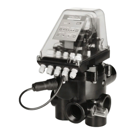
Astral Pool VRAC III Basic Series Manual

S Y S T E M V R A C I I I
INSTALLATION AND MAINTENANCE MANUAL
MANUEL D’INSTALLATION ET D’ENTRETIEN
MANUAL DE INSTALACIÓNY MANTENIMIENTO
MANUALE DI INSTALLAZIONE E MANUTENZIONE
INSTALLATIONS-UND BEDIENUNGSANLEITUNGEN
MANUAL DE INSTALAÇÃO E MANUTENÇÃO
Modbus® is a registered trademark of the Modbus
Organization, Inc.
BASIC AUTOMATIC MULTIPORT VALVE
VANNE MULTIVOIES AUTOMATIQUE BASIC
VÁLVULA SELECTORA AUTOMÁTICA BASIC
VALVOLA SELETTRICE AUTOMATICA BASIC
AUTOMATISCHES MEHRWEGE VENTIL BASIC
VÁLVULA SELECTORA AUTOMÁTICA BASIC


DECLARACIÓN DE CONFORMIDAD CE / EC DECLARATION OF CONFORMITY
El fabricante / the manufacturer: CEPEX, S.A.U.
Avinguda Ramon Ciurans 40 (Parcel·la 6)
Polígon Industrial Congost
08530 LA GARRIGA - Spain
Certica que nuestro / declara que nuestro actuador / certify that our / declares that our
actuator:
Tipo / type:
SystemVRAC Basic 230-115Vca - 50 / 60 Hz para válvulas selectoras automáticas.
SystemVRAC Basic 230-115Vac - 50 / 60 Hz for automatic multiport valves.
Modelos / Models:
70768-0100, 70769-0100
cumple con los requisitos establecidos por la UNIÓN EUROPEA de acuerdo con las directivas:
meets the requirements established by the European Union according to the Directives:
- Directiva de BajaTensión 2006/95/CE según norma:
- Low Voltage Directive 2006/95/CE in accordance with the standards:
UNE-EN 60335-1: 2012 / AC: 2014 / A11: 2014
Aparatos electrodomésticos y análogos. Seguridad. Parte 1: Requisitos generales.
Household and similar electrical appliances - Safety - Part 1: General requirements.
- Directiva de Compatibilidad Electromagnética EMC 2004/108/CE según normas:
- Electromagnetic Compatibility Directive EMC 2004/108/CE in accordance with the standards:
UNE-EN 61000-6-1: 2007
Compatibilidad Electromagnética (CEM). Parte 6: Normas genéricas. Sección 1: Inmunidad en
entornos residenciales, comerciales y de industria ligera.
Electromagnetic compatibility (EMC). Generic standards. Immunity for residential, commercial
and light-industrial environments.
UNE-EN 61000-6-3:2007 + A1: 2011
Compatibilidad Electromagnética (CEM). Parte 6: Normas genéricas. Sección 3: Norma de emi-
sión en entornos residenciales, comerciales y de industria ligera.
Electromagnetic compatibility (EMC). Generic standards. Emission standard for residential,
commercial and light-industrial environments.
- Directiva RoHS 2011/65/UE según norma IEC 62321.
- RoHS Directive 2011/65/UE in accordance with the standard IEC 62321.
Y Por el cumplimiento de estas directivas, nuestro actuador puede incorporar la marca CE.
By accomplishing these directives, our actuator can incorporate the CE mark.
Y ser vendidos en la UNIÓN EUROPEA cumpliendo con los requisitos legales.
And they can be sold throughout EUROPEAN UNION providing all legal requirements.
Yasmin Fernández
Quality Management
La Garriga, Julio 2018

4
ENGLISH
"Important:Thisinstructionmanualcontainsbasicinformationwithrespect tosafetymeasureswhich
shouldbe adoptedduringinstallationandputtinginto service.Forthisreason,itisessentialthatboth
the installer and user carefully read these instructions before carrying out any installation or putting
into service operations."
In order to obtain optimum performance from the automatic valve, it is recommended that the instruc-
tions given below are strictly followed.
General safety prescriptions:
These symbols indicate the possibility of danger as the consequence of not respecting
the corresponding prescriptions.
DANGER. Risk of electrocution.The lack of warning of this prescription involves a risk of electrocution.
DANGER. The lack of warning of this prescription involves a risk of personal injury or material damages.
WARNING. The lack of warning of this prescription involves a risk of damage to the automatic valve or
the installation.
GENERAL SAFETY REGULATIONS .
GENERAL.
The valve described in this manual has been specially designed to provide correct water circulation in the
swimming pool during the various operational phases.
It has been designed to work with clean water at temperatures not exceeding 35ºC.
The installation must be carried out in accordance with the specic instructions for each particular
implementation.
Current in-force regulations for the prevention of accidents must be observed.
Any modication to the valve’s electronic module requires the prior authorisation from the manufacturer.
Original spare parts and accessories authorised by the manufacturer will guarantee greater safety.
The manufacturer of this automatic valve is exempt from all responsibility for any damage caused by
nonauthorised spare parts or accessories.
During operation, the valve’s electric and electronic parts have electric power connected to them.
Any work to the automatic valve and any equipment connected to it, must only be carried out when the
start-up devices have been disconnected.
The user must ensure that installation and maintenance work is carried out by adequately qualied and
authorised personnel, and these have previously carefully read the installation and service instructions.
Automatic valve operational safety is only guaranteed by full compliance and respect of the installation
and service instructions.
The maximum voltage values must never be exceeded under any circumstances.
In the case of incorrect operation or a fault, please contact the closest manufacturer’s representative or
technical assistance service.
The appliance is not to be used by persons (including children) with reduced physical, sensory or mental
capabilities, or lack of experience and knowledge, unless they have been given supervision or instruction.
Children being supervised not to play with the appliance.

5
ENGLISH
ADVICE DURING INSTALLATION AND ASSEMBLY OPERATIONS.
During the connection operations of the electrical wiring to the valve modules, great attention must be
given to polarity, and it must be veried that pieces of wiring are not left inside after closing.
Make all connections by following the instructions in this manual.
It should be veried that the electrical wiring connections to the valves electronic card are rmly made.
The seal on the module’s box should be checked for correct positioning to prevent the entry of water, it
should also be checked that the compression gland is also correctly located and that the cables are of a
correct length. Cover the unused compression glands to ensure the IP grade.
Particular attention should be paid, so that, under no circumstances, is it possible for water to enter the
electronic module. In the case where the intended use is not that for which the valve was designed,
adaptation and supplementary technical regulations may be necessary.
ADVICE FOR WHEN PUTTING INTO SERVICE.
Before putting the automatic valve into service, it is necessary to verify the calibration of the electrical
protection devices in the operations cabinet and that they are correctly positioned and xed in place.
NOTE: It is recommended that the bathing facilities are not used while the ltration equipment is in
operation.
ADVICE DURING INSTALLATION AND MAINTENANCE WORK.
Nationalinstallationregulationsmustbetakenintoaccountwhenassemblingandinstallingtheautomatic
valve. Extra care must be taken so that it is not possible, under any circumstances, for water to enter the
automatic valve electronic circuit.
All contact, including accidental, must be avoided at all times with the moving parts in the automatic
valve during operation and/or before complete shutdown.
Before carrying out any maintenance or any other electrical or electronic work, it must be ensured that
switch-on devices are locked.
Itisrecommendedthatthefollowingstepsbetakenbeforeperforminganymaintenanceontheautomatic
valve.
1.- Remove electrical power to the valve.
2.- Lock the switch-on devices.
3.- Verify that there is no electrical power being applied to the circuits, including auxiliary and
supplementary services.
This list must be considered indicative and not binding with respect to safety, there may be other specic
safety standards in particular regulations.
IMPORTANT: due to the complexity of the situations covered, the instructions for installation, use
and maintenance contained in this manual, do not make any attempt to cover all possible service and
maintenancecases.Ifadditionalinstructionsarenecessaryorspecicproblemsarise,pleasedonothesitate
in contacting the distributor or the valve manufacturer directly.
Our automatic valves may only be installed in swimming or other pools which fully comply with the HD
384.7.702 standard. When any doubt exists a specialist should be consulted.
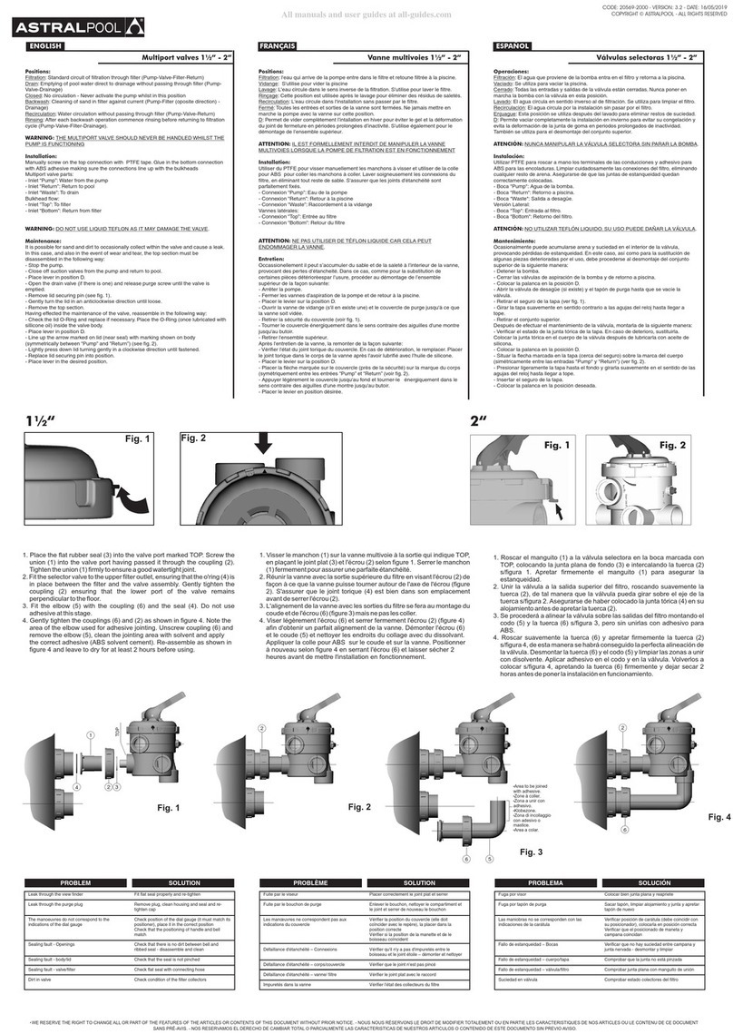
Please check the packing contents.

6
ENGLISH
CONTENTS
1. Valve characterisctics.
1.1 Specications
1.2 Flow diagram for the various valve operating positions.
1.2.1 Filtration position
1.2.2 Backwash position
1.2.3 Rinse position
1.2.4 Closed position
1.2.5 Recirculation position
2. Installation.
2.1 Hydraulic installation
2.2 Electrical connection.
2.3 Example of connecting a single phase 230 V electrical cabinet.
2.4 Fuse.
2.5 Pressure switch adjustment.
2.6 Drainage safety.
3. Maintenance and guarantee.
3.1 Hydraulic installation maintenance.
3.2 Specic valve maintenance.
3.3 Guarantees.
4. Operating and programming.
4.1 Control panel.
4.2 Washing cycle.
4.2.1 Washing by timing of the washing cycle.
4.2.2 Washing using the press button.
4.2.3 Washing by pressure
4.3 Programming of washing and rinsing times
4.4 Drainage
4.4.1 On“ltration”position and while programming is stopped.
4.4.2 Forced while timer programme is running).
4.5 Closed
4.6 Recirculation
4.7 Indication of faults.
5. Instructions for removing the module installed on the valve.
5.1 Disassembly of the electronic module.
5.2 Instructions for installing the module on the valve.
5.3 Temporary conversion of the system to manual operation.
5.4 How to change the valve from manual to automatic operation.
6. MODBUS
7. Solution of possible problems.
8. Annexes.
8.1 Appendix 1:Valve assembly and dismantling.

7
ENGLISH
1. VALVE CHARACTERISTICS
1.1 SPECIFICATIONS.
Two valve models with actuator:
- Selector valve 1 ½ "VRAC BASIC System.
- Selector valve 2 "VRAC BASIC System.
The valve assembly to the lter will be LATERAL or TOP depending on the code requested.
Materials: Valve body: ABS.
Internal distributor: PPO.
Spring: AISI-302 coated stainless steel. Screws: AISI-316 stainless steel.
Connection of theTOP, RETURN andWASTE openings through BSP or NPT female threads.
In the case of lateral mounting, the BOTTOM opening of the body is provided for bonding using glue.The
connection kit to a side lter with a 125 mm (1 ½ ") or 230 mm (2") height is included. See hydraulic
connection sheet.
Maximum working pressure: 350 kPa (3.5 bar).
Test pressure: 520 kPa (5.2 bar).
Maximum service life: 5,000 washing and rinsing programmes.Temperature range: 5 - 35 ºC.
Degree of protection of the electronic module: IP-65. Maximum power = 35W.
Power supply: 115 - 230VAC (50-60 Hz).
Maximum expected height use of 2,000 m above sea level.
Asensorandaresistorhavebeeninstalledinthecontrolmoduletomaintainasuitableindoortemperature
to avoid condensation caused by thermal dierences that could damage the electronics.
Intendeduse:the valveisspeciallydesignedtobeappliedinpoolltrationsystemsusingasandlter.The
plannednumberofoperationsissucientlydimensionedforthisapplication.Checkwiththemanufacturer
for other uses.
An alarm that limits the number of maximum pressure washes in a single day has been added so as to
limit its use to pool ltration systems, so that priority is given to the pool not being emptied due to poor
conguration of the system.
The hydraulic and electric operation of the valve is checked at the factory
1.2 FLOW DIAGRAM FOR THEVARIOUS VALVE OPERATING POSITIONS.
The valve should be installed in the lter following the instructions provided in the hydraulic connection
diagram.
Installation under load, the maximum water column that can be supported by the pump is six metres
(19.68 ft).
The hydraulic connections for correct operation are made by following the markings on the valve itself.
PUMP indicates the connection coming from the pump.
TOP indicates the upper input to the lter.
BOTTOM indicates the lower exit from the lter to the valve.
RETURN indicates the return from the valve to the swimming pool.
WASTE indicates the connection to the drains.

8
ENGLISH
1.2.2 Backwash position
The valve automatically reverses the ltration cycle and commences the ltering process. This function
requires that the valve is set so that the water coming from the PUMP connection passes through the
valve and is taken to the lter by the BOTTOM connection, the sand is stirred and the water, together with
any accumulated dirt exits the valve TOP connection which communicates with the WASTE connection
(emptying) and is taken to the drain. This process is carried out in accordance with the pre-established
timing on the keyboard.
1.2.3 Rinse position
The valve is positioned to compress the lter bed and not to send water containing sand to the swimming
pool.This function is achieved by water coming from the PUMP connection entering the lter by theTOP
connection, it thencompresses thesandand thewaterentersthevalvevia theBOTTOM connection which
then sends it to theWASTE connection. This process is carried out in function of the pre-established time
and once it has elapsed, the valve commences the ltration process again.
1.2.1 Filtration position:
The pump sucks water from the swimming pool via the skimmer, bottom cleaner or drain, it is taken to
the multiport valve (PUMP connection) and from here to the lter (TOP). It passes through the lter bed
and returns to the valve once again via the BOTTOM connection and is taken back to the swimming pool
by means of the RETURN connection.
The valve includes a pressure switch that determines the saturation pressure of the lter and therefore
whenitisnecessarytocarryoutawashingandrinsingprocessofthelter.Therangeofthepressureswitch
is from 30 to 200 kPa (0,3 - 2 bar / 4.2 – 28.4 psi), which is factory set to an operating pressure of 200 kPa
(2 bar) (29 psi). A new specic regulation of the pressure switch should be carried out for each installation
so that the operating system to wash the lter is correct. (see paragraph 2.5).
If the pressure exceeds the pre-established limit, the valve will automatically change position to start a
washing and rinsing cycle. This cycle can also be automatically time controlled, after 24 hours or 7 days
from when the last wash was carried out, as long as the valve is connected to the electricity.
Valve in ltration
process
Valve in
washing
position
Valve in rinsing
position
1.2.4 Closed position
The valve is positioned in such a way that the ow that comes in through the PUMP opening, from the
pump, is isolated from the other openings.

9
ENGLISH
2. INSTALLATION.
2.1 HYDRAULIC INSTALLATION.
Thespecicsheetforthehydraulicconnectionofthevalvetothelterisattached.Pleasetakeintoaccount
the following warnings:
- Apply PTFE sealing tape on the male thread elements, avoiding sealing paste under all circumstances.
- The use of 3 piece links between the valve and the rest of the installation is recommended to facilitate
possible maintenance tasks.
- Always install a ball valve in the return pipes to the pool.
- Use a suitable glue for the ABS to glue the elbow supplied for the BOTTOM opening of the valve body.
2.2 ELECTRICAL CONNECTION.
Thecontrolmoduleoftheautomaticvalvewillalwaysbeconnectedtoacontrolcabinetthatwilldetermine
the ltration times of the pool by means of a timer. The minimum components that the control cabinet
must have are: dierential (advisable), circuit breaker, pump contactor, position switch (on"II" / high "I")
and programmer clock.
The contactor controls the ltration pump and the valve is connected to the operation of this contactor
in series to the connection coming from the timer in order to stop the pump.
Follow the following instructions in order to prepare the control box and its connection to the electronic
module:
-Powersupply:115-230Vac. Itis advisabletotakethe current fromthecontrolbox connect tothe "out"
terminal of the dierential (if used), or else connect the L, N and T terminals from the magneto thermal
breakertothecorrespondingL,NandTterminalsoftheelectronicmodule.Thisconnectionhasnopolarity.
We recommend that a 3 wire earthed cable of 0.75 mm2 is used (H05VV-F) with a cord diameter of 5 to
6.7mm(Tighteningtorque:1.5Nm).ThecableshouldmeetthespecicationsforLowVoltageRegulation,
as well as other local regulations.
It is mandatory to install a multiple switch that allow the power failure of the device from the control
box.
It's essential for the valve to have the power supply switched on at all times, to guarantee
that the anti-condensation device works properly.
- Control of the contactor solenoid pump: connect series terminals 4-5 of the valve with the input
connection to thecontactorcoil A1.Thevalvewill stop thepump when anyoperationneeds tobe carried
out.We recommend that a 2 thread cable of 0.75 mm2 is used (H05VV-F) with a cord diameter of 5 to 6.7
mm (Tightening torque: 1.5 Nm).This connection has no polarity.
This connection must be made for the valve's correct functioning, as the electronics detects a minimum
consumption to thus avoid, that the operations are carried out with the pressure pump working which
could damage the valve.
It is important that only the solenoid contactor is connected and that there is no other power source
connected so that 0.4 A are exceeded.
1.2.5 Recirculation position
Inthisposition,waterfromthepumpowsdirectlyintothepoolthroughtheRETURNnozzleafterpassing
through the valve, thus not passing through the lter.

10
ENGLISH
ELECTRICAL CONNECTION BETWEEN THE CONTROL CABINET AND THE VALVE
A1 / A2 are the terminals used to connect the ltration pump's contactor coil.Ter-
minal J10 of the multiport valve must always be connected to connection A1 of the
contactor coil. The J10 socket (4-5) of the selector valve must always be connected
to A1 connection of the contactor coil.
We should ensure that the contactor's operation line, which is connected in series to
the valve does not under any circumstances share the power supply with any other
device, and the intensity of the operation line never exceeds 400 mA. If this point is
omitted it may cause irreversible damage to the equipment.
In cases where another component has to be connected which needs be activated
at the same time as the pump, we recommend the use of an auxiliary contact of the
pump contactor.
In the event the supply of the valve is connected to a three-phase electrical circuit, always make the on-
nection between one phase and the neutral, never between two phases, since that way the maximum
voltage allowed by the valve electronics would be exceeded.
The control circuit (for example contactor's coil of ltration pump) is powered at U andV in this schema.
U andV can be Alternative Current (AC) where U is Line andV is Neutral, or Direct Current
(DC), where U isVdc and V is GND.
Maximum voltage = 230V.
ELECTRIC SUPPLY
230Vac
TIMER
3 positions switch:
2 AUTOMATIC (TIMER)
0 STOP
1 MANUAL
Contactor's coil of Filtration
Pump CONTACTOR
PUMP
PRESSURE SWITCH
COMMUNICATION
PROTOCOL
MODBUS

11
ENGLISH
2.3 EXAMPLE OF CONNECTING A SINGLE PHASE 230 V ELECTRICAL CABINET
Before proceeding with the installation of the materials, users must ensure that the assembly and
maintenance work is carried out by qualied and authorised workers who have read and unders-
tood the installation and service instructions.The following diagram shows the external connec-
tions required to connect a SystemVRAC multiport valve to an ASTRALPOOL 25717 cabinet.
Disconnect the A1 end of the cable leading from connection 2 of the 3-position switch and add a
terminal block for the valve control connection.

12
ENGLISH
2.4 FUSE .
The valve's electronics board incorporates a safety fuse to prevent any damage being caused to the J10
connection (terminals 4 and 5).
As stated in the previous point, incorrect connections or other connected components which increase
power consumption at the connection between the solenoid valve of the pump contactor and the valve
may result in operational faults.
A fuse therefore prevents the consumption through this conductor exceeding 0.4 A, thus preventing such
faults.Intheeventthatthefusefails,checktheelectricalinstallationtoensurethatitmatchestheelectrical
diagram before replacing the fuse with a new one of the same specications.
2.5 PRESSURE SWITCH ADJUSTMENT.
Use the lter or valve manometer as a reference guide when reading the pressure gauge. Proceed as
follows:
1ºTurn the pressure switch screw (1) (APPENDIX 1 - g. 1) until it is ush with the black piece (it is not
necessary to tighten it all the way).
2º With the pump running, close the return valve to the swimming pool until you can read on the
manometer the maximum pressure you wish the equipment to be run on. This point is the pressure
value at which the valve will start the backwash and rinse process of the lter.
3º Gently loosen the screw (1) (ANNEX 1 - Fig. 1) of the pressure switch until the green LED backwash
button light of the control panel comes on (see chapter 4.1 of this manual). After approximately 20
seconds, the pump will stop and start the wash routine.
4º IMPORTANT. Open the pool return valve.
The pool’s return tube has to be equipped with a ball valve to ensure a correct adjustment.
2.6 DRAINAGE SAFETY.
The valve comes ready to be installed in an electrovalve in the drainage circuit. Its use is recommended in
order to avoid water loss in case there is no electrical connection and the valve ends up in a position that
could lead to the pool emptying. The electrovalve used should have as low a pump pressure orice as
possible,maximum40 -50kPa(0.4- 0.5bar).Thevoltageofthesolenoidshouldbe 24Vac(See APPENDIX
1 - Fig. 9).
F 400mA L 250V

13
ENGLISH
Grease
3.3 GUARANTEES.
The valves leave the factory in a fully tested condition, which enables us to guarantee operation. The
guarantee will be eective provided that the installation and maintenance has been correctly carried
out and this requires that the actual installation operation be performed by a person with the necessary
qualications for this type of work. A specic sheet with the valve guarantees is attached to the manual.
3. MAINTENANCE AND GUARANTEES.
3.1 HYDRAULIC INSTALLATION MAINTENANCE
Regular maintenance needs to be carried out on all components of the pool's hydraulic circuit in order
to ensure optimum operation of the installation and thereby prevent damage to the valve or any other
components.
The maintenance operations that may have a direct impact on the operation of the multiport valve are
listed below:
- Be sure to empty and wash the skimmer baskets on a regular basis to keep them clear of leaves and any
other waste. Baskets should be replaced if they are damaged.
- Be sure to empty the basket of the pump pre-lter, clearing away leaves and any other waste. Replace
the basket in the event of damage.
- Regulate the suction and return valves by adjusting the valve's pressure switch before setting the lter
wash pressure. This operation should be repeated whenever a component is changed or added to the
installation or whenever the regulation setting of the valves is changed.
3.2 SPECIFIC VALVE MAINTENANCE
The internal elements of the valve require regular maintenance in accordance with the following
specications:
- Perform all operations with the pump o and with the input and output valves to the lter and the
multiport valve closed.
- Remove the actuator as described in point 5.4 of the manual.
- Remove the remaining 3 screws holding the valve cover in place.
- Remove the cover to allow access to the internal distributor.
- Lift the distributor and clean the area around the distributor seal, clearing away any residue that may
hinder rotation.
- At least once a year, grease the O-rings on the distributor shaft to facilitate the movement of the
distributor.The grease used to lubricate the O-rings should be TURMSILON GL320 NLGI 1-2 (LUBCON).
Themanufacturersuppliesthespeciedgreasetogetherwiththevalve.Theuseofunauthorisedgrease
canirreversiblydamagesomecomponentsofthevalveandthereforecausetheguaranteetobeinvalid.
- Reassemble the distributor. Mount the cover with the previously assembled gasket and x it with the 3
screws and the 3 nuts, with the proper torque to ensure the seal.
- Mount the hood on the distributor shaft, matching the triangle mark with the notch (8) of the bell. Fit
the pin (6)
- Fit the cam-ratchet (5), according to Figure 7.
- Fasten the screw (3) to the end and loosen it a quarter of a turn.
- Mount the actuator and x it with the remaining screws and nuts.

14
ENGLISH
4. OPERATING ANG PROGRAMMING
4.1 CONTROL PANEL
The valve incorporates in the electronic module cover a panel with push buttons and LEDs to indicate the
function being performed by the valve.
4.2 WASHING CYCLE
4.2.1 Washing by timing of the washing cycle
The washing cycle interval of the keyboard allows a washing and rinsing cycle to be carried out once the
programmed time has elapsed, 24 hours or 7 days.
The timer will reset when:
-The timed cleaning function has been completed.
- A pressure switch backwash has completed.
-The backwash is nished though a push button.
- Power is connected or reconnected after a power outage.
The washes will be done only using pressure in the“OFF”position.
4.2.2 Washing using the press button
The button allows you to start a lter washing routine (washing + rinsing) without having to manipulate
the pressure switch or the return valve. The valve must be correctly connected to the electrical cabinet
and the timer lter programme activated.
If there is a power cut, the backwash and rinse times will remain stored in the valve until the valve once
has a power supply again.
Power supply: LED that indicates that the valve's power supply connection has
been correctly done.
MODBUS Communication: In case of connection in done through MODBUS, it
indicates when data is sent or received.
Connection (4-5): LED indicating that the solenoid of the contactor is active
and that the pump is therefore running.
Cyclewashpressbutton:Pressbuttontoactivatethewash+rinseprogramme.
Empty press button: Press button to activate the emptying function.
Press button for recirculating: Press button to activate the recirculation
function and that indicates that the function is in process.
Closed press button: Press button to move the valve to closed position.
Washing cycle interval: it is possible to programme a daily (every 24h), weekly
(7 days) wash or disable it (OFF).
Backwash time: the push buttons can increase or reduce the backwash time
and the activation of one of the LEDs shows the minutes of programmed wash. It
ashes when the function is running.
Rinse time: the push buttons can increase or reduce the rinse time and the
activation of one of the LEDs shows the rinse time selected. It ashes when the
function is running.
The LEDs on the wheel correspond to the position of the valve.They also indicate with short ashes if the
valve moves to that position and with a long ashes if the programme has remained in the memory at
the end of the ltration time.

15
ENGLISH
A single press starts the routine, which can be cancelled at any time by pressing the button again, so that
the valve returns to the ltering position. During the valve’s change of position, the LED of the button
ashes. Once the routine is nished, the valve will return to Filtration.
4.2.3 Washing by pressure
When the valve is in the Filtration position and the pump is running, an automatic washing and rinsing
programme will be carried out when the lter pressure exceeds the pressure set on the pressure switch
for more than 20s.The LED of the washing position also indicates the activation of the pressure switch
when the pressure exceeds the set value. See "Adjusting the pressure switch".
4.3 PROGRAMMING TIMES FOR WASHING AND RINSE.
The ltration time must be programmed using the programming clock installed in the control cabinet.
To programme the washing time, use the corresponding buttons on the programming page to select the
desired time in minutes, with the corresponding LED being illuminated. When the valve is performing
this function, the LED will ash.
Toprogrammethe Rinsetime,usethe keysonthe keyboardtoselectthe desiredtimein seconds,with the
corresponding LED being illuminated.When the valve performs this function, the LED will ash.
If during the wash or rinse function, the timer clock determines the end of the ltering programme, the
valve will be in Filtration and the corresponding LED will indicate a long ash (the programme remains in
thememory).Whentheprogrammeisre-enteredthefunctionwillendtheprogrammethatwasunderway
at the time it was stopped.This washing and rinsing memory will only be maintained as long as there is a
powersupply.Itwillnotbepossibletochangethesetimeswhilethevalveisinawashingorrinsingprocess.
4.4 DRAINAGE
4.4.1 In the ltering position and outside the timer ltering programme.
To perform the operation manually, please follow the instructions below:
Press the waste button on the electronic module for 3 seconds, the valve will now be in the Drainage
position.
Turn the switch in the control box to the“I”position, thus activating the pump and starting the drainage
process.
These operations are to be carried out when the valve is in the“ltration”position. If the wash or rinse
cycles are running, please wait until they have nished.
Appliance users should watch for when this operation nishes. Once the appliance has stopped, proceed
as follows:
In the control panel, briey press the drainage button
1ºTurn switch to“II”position in the control box in order to stop the pump.
4.4.2 Forced while timer program running
Press the drainage button for3 seconds.The electronic module will stop the pump and the valve will
turn to“WASTE”position. The pump will start up again.To stop the drainage press the button briey
again.The module will stop the pump and it will be positioned in Filtration and will activate it again.

16
ENGLISH
4.5 CLOSED.
In order for the valve to be placed in the closed position, it will be necessary to be in the Filtration position
and with the pump running. By briey pressing the corresponding button, the valve will change position,
the LED will remain lit and the lter pump will stop. Pressing again will cancel the function, so the valve
willreturntoFiltrationand leave thepump running.Intheeventoftheendoftheltrationtime,the valve
will move to the Filtration position and the Closed function will be cancelled. Proceed as in 4.4.2 to force
the closed position out of the ltration time.
4.6 RECIRCULATION.
In order for the valve to be placed in the Recirculation position, it will be necessary to be in the Filtration
position and with the pump running. By briey pressing the corresponding button, the valve will change
position, the LED will remain on and the pump will remain active. Pressing again will cancel the function,
so the valve will return to Filtration and leave the pump running. In the event of the end of the ltration
time,thevalvewillmovetotheFiltrationpositionandtheRecirculationfunctionwillremaininthememory
(with the LED with a long ash), to continue when the pump is back on.
4.7 INDICATION OF FAULTS.
If some of the programmed errors are detected, the valve will start an operation to, whenever possible,
put itself into the ltration process and stop the pump, to be in a position where there is no unnecessary
loss of water.
Through the simultaneous ashing of the LEDs for power supply, wash time and back-wash time, we can
detect the valve's possible operating faults with the following code:
- Flashes once: failure in the micro ltration position or the motor does not turn.
- Two ashes: fault in any micro position except for the ltration one.
- Flashes three times: failure in the micro ratchet due to a possible break in the ratchet.
- Flashes four times: excess motor load because the distributor has been stopped.
Itis possiblethatthereissome externalelementthatstopsthe distributor goinground dueto anincorrect
maintenance of the hydraulic installation, or through the lack of maintenance of the valve itself.
Alwaysactasindicatedintherelevantpointsofthismanual:"Solutionofpossibleproblems,""Maintenance
of the hydraulic installation" and" Specic maintenance of the valve."
The valve carries out two operating attempts and whenever possible, will try to position itself in ltration
to show the error.
At rst it does not require any action from the manufacturer'sTechnical Service. In case of requiring their
helpwiththistypeoferror,werecommendthatwheneverpossible,thevalveandactuatoraresenttogether.
- Flashes six times: failure of the distributor ascend micro.
- Flashes eight times: an error is activated that indicates that more than 3 wash programmes of t h e
lter have been carried out in less than 24 h activated by a pressure sensor.This is indicative of some error
in the pressure switch adjustment, or either the cable or the pressure switch is faulty.
Torestartthe errorindicationinthevalveitisnecessary todisconnectthevalve'spowersupplyfrom
the control box for a few seconds (until all the LEDs have been switched o).
It is also possible to reset the signalling of the last alarm by pressing at the same time in the keyboard
Rinse Time minus and Rinse time plus during 5 s.

17
ENGLISH
5. INSTRUCTIONS FOR REMOVING THE MODULE INSTALLED ON THE VALVE
The valveconsistsoftwosections,thehydraulicpartwhichincludesaconventionalvalveandanautomatic
module.The complete valve is disassembled of the lter in the same manner as a manual valve.
5.1 DISASSEMBLY OF THE ELECTRONIC MODULE:
(See illustrations in APPENDIX 1) BEFORE ANY OPERATION IS CARRIED OUT ONTHEVALVE, IT MUST BE
DISCONNECTED FROMTHE POWER SUPPLY.
Remove the four screws which hold the cover (1) in place. (Fig. 2).
Disconnect all input wires to the module (AAPPENDIX 1 - Fig. 8). WARNING: All mains power supply
connections must be removed rst.
Ret the cover 1 (Fig. 2).
Remove the three screws (11) which hold the module in place on the valve (Fig. 3). Carefully remove the
module in an upwards direction.
Protectinside suitablepackaging to preventanydamage andsendit to themanufacturer.Fromthispoint
there are two possibilities:
1. Replacement of the module.
2.Temporarily convert the system to manual valve operation.
5.2 INSTRUCTIONS FOR INSTALLING THE MODULE ON THE VALVE.
The manufacturer will ship the valve-module assembly to the technical service or installer ready for
installation. It should be installed as follows:
1. Install the valve assembly by positioning the module so that marking 2 (APPENDIX 1 - Fig. 3) coincides
with the mark on the valve cover, carefully lower the module until it is correctly in place with respect to
the screw 3 (APPENDIX 1 - Fig. 4). In a situation where it does not t, the screw may be rotated until it
coupleswith themotorpin (4)(APPENDIX1- Fig.4).Caremust betakennot tolowerittoo brusquelysince
this could damage the module’s microswitches.
2. Install the three screws (11) (APPENDIX 1 - Fig. 3 ).
3. Remove the cover 1 (APPENDIX 1 - Fig. 2) by removing the four screws (13) in order to access the
connection strip.
4. Connection (MAKE SURETHERE IS NO MAINSVOLTAGE). Connect the cables as indicated in the attached
diagram. IMPORTANT! Use the gland seals that come installed in the module.
5. Replace the cover 1 (APPENDIX 1 - Fig. 2) and replace it with the screws (13).
6. Connect the power input to the control board.The valve will be in the Filtration position, remaining in
operating position when the programmed time comes into operation
5.3 TEMPORARY CONVERSION OF THE SYSTEM TO MANUAL OPERATION.
The module should be dismounted as described in Section 5.1.
Oncethe supplysystemis out,unplug thewiresin thecontrolbox(L-N) thatsupplythe electronicmodule.
Disconnect the wires from terminal (J10) on the electronic module and connect them to each other with
a bridge between these two terminals.
Remove screw (3) (APPENDIX 1 - Fig. 4), and pull the pawl (5) upwards, then (see APPENDIX 1 - Fig. 5)
remove the pin (6) in the direction of the arrow sale, remove part (7), leaving the valve in position for
installing the handle.

18
ENGLISH
To install the handle, position the handle* (14) (APPENDIX 1 - Fig. 6) such that the triangle on the bell
shaft always coincides with the handle positioner (9). Once it is installed, the pin* (10) can be inserted .
Inthe eventthat thereisanelectrovalvein thedrainage system, turnthe lever(APPENDIX1- Fig.9- detail
1) to position manual.
The 3 position switch, On“II”, Hi“I”should be in the“I”position.
* Supplied as spare parts.
5.4 HOW TO CHANGE THE VALVE FROM MANUAL TO AUTOMATIC OPERATION.
Remove the pin (10) (APPENDIX 1 - Fig. 6), remove the handle (14) and install the part (7) (APPENDIX 1 -
Fig. 5).This is accomplished by orienting the mark (A) such that it coincides with the triangle (APPENDIX
1-Fig. 6).Oncettedinplace,the pin(6)(APPENDIX1-Fig. 5)shouldbe inserted,whichshouldbe centred
along its length.Then install the part (5) (APPENDIX 1 - Fig. 4). Slot the inside notch (15) into the
mark (16). See assembly illustration in APPENDIX 1, g.7.Which should be well-positioned (it only has
one mounting direction). Insert the screw (3) and screw in. It should not be fully tightened since it has to
be loosened in order to orient it with the pin (4) on the motor assembly. At this point, it is now possible
to install the module assembly as described in the valve module installation process.
Inthe eventthat thereisanelectrovalvein thedrainage system, turnthe lever(APPENDIX1- Fig.9- detail
1) to position nº2 (automatic).
Control box:The 3 position switch, On“II”, Hi“I”should be in the“II”position.
6. MODBUS.
You have bought the automatic selector valve that includes the features of the MODBUS RTU.
MODBUS is an open communication bus that is widely used to connect dierent devices to a main control.
This is the reason why this standard of communication has been chosen, it is easy to integrate with other
products of the same brand and even with a wide range of products from other suppliers.
MODBUS, MODBUS-RTU and other related names are registered brands of MODBUS Organization. It is
possible to obtain additional information and documentation at http://www.modbus.org/.
MODBUS allows the control and supervision of some of the valve operations, as well as helping in
preventative maintenance and the analysis of defects, thanks to the implementation of internal registers
on the possible actions and most relevant errors.
The valve is ready to work with MODBUS, but it can work in a local mode like a traditional valve without
the need to connect the communication system.
The control system allows it, for example, to be moved to a specic position, inform on errors and on the
operating history and other features that oer the user/installer a wide range of new possibilities based
on automation.
Toobtainmoreinformation,consultthespecicmanualofMODBUS,thatis providedbythe manufacturer.
7. SOLUTION OF POSSIBLE PROBLEMS.
We attach a list of possible problems that can occur with the valve, together with the best solution.
IftheMODBUScommunicationbusisused,pleaseconsultthespecicmanualtosolvethepossibleincidents.

19
ENGLISH
PROBLEM CAUSE SOLUTION
The valve does not start up and the
LED is not lit up. Incorrect electrical connection Check the power connection solenoid.
The LED is lit but the back-wash does
not start. Incorrect electrical connection Check the LED Connection (4-5) is active. If not,
check the electrical connection of the pump's
solenoid to terminal J10 (4-5).
The ltration pump is not working Check that the electric cabinet timer keeps the pump
running.
The actuator does not work and the
LEDs ash once. Failure in ltration position or the
motor does not turn. Contact technical assistance or request a spare part
for the motor unit.
The actuator does not work and the
LEDs ashes twice. Failure in any micro position except
for the ltering one. Contact technical assistance.
The actuator does not work and the
LEDs ash 3 times. Failure in the micro ratchet. Contact technical assistance.
The actuator does not work and the
red light ash 4 times. The valve distributor is blocked. DISCONNECT THE POWER SUPPLY AND TAKE OFF
THE ACTUATOR.
Take o the valve lid, clean the distributor and apply
grease shaft and o-rings withTURMSILON GL320
grease.
The actuator does not work and the
LEDs ash 6 times. Problem with the distributor ascend
micro. Restart the valve's power supply for a few seconds.
If this persists, contact technical assistance.
The buttons on the keypad do not
work. The connecting cable is discon-
nected Check that it is correctly connected
The actuator does not work and the
LED ash 8 times More than 3 pressure washes have
been carried out in less than 24h
due to a bad adjustment or through
a failure of the pressure switch.
Adjust the pressure switch correctly. If this persists,
contact technical assistance to obtain a spare part for
the pressure switch.
There have been more than 3
washes in less than 24h because the
return ball valve is closed or nearly
closed.
Open the ball valve and restart the power supply of
the valve or restart the last error incation.
There have been more than 3
washes in less than 24h due to the
defect in the pressure switch cable
Check the pressure switch connection cable.
The valve does not work and the fuse
has blown. There is an incorrect electrical con-
nection producing an excessive level
of power consumption at terminal
J10 (4-5) of the valve.
Measure the power supply in the 4-5 connection
and review the electrical installation. Change the
fuse when the connection problem is solved (it is
delivered as a spare part).
The waste water electro-valve does
not open (in the case that it has been
installed)
The polarity of the cables has not
been respected Change the cables connection: red (+) and black (-).
Error in the electronic board Check the power in the solenoid valve terminal strip:
if it's less than 15Vcc, contact technical assistance.
Error in the electro-valve If the tension is correct, the problem has tobe in the
electro-valve.

20
FRANÇAIS
"Important:Laprésentenoticed’instructionscontientdesinformationsessentiellesquantauxmesures
desécuritéàadopterlorsdel’installationetdelamiseenservice.Ilestdoncimpératifquel’installateur,
mais aussi l’utilisateur, lisent attentivement ces instructions avant tout montage et toute mise en
marche."
Pour un rendement optimal de la vanne automatique, il est important de respecter les consignes ci-
après:
Consignes générales de sécurité:
Les symboles signalent un danger éventuel en cas de non respect des consignes
correspondantes.
DANGER. Risque d’électrocution. Le non-respect de cette consigne entraîne un risque d’électrocution.
DANGER. Le non-respect de cette consigne implique un risque de dommage corporel ou matériel.
ATTENTION ! Le non-respect de cette consigne comporte un risque d’endommagement de la vanne
automatique ou de l’installation.
CONSIGNES GÉNÉRALES DE SÉCURITÉ
GÉNÉRALITÉS
La vanne mentionnée dans ce manuel a été spécialement conçue pour assurer la circulation de l’eau dans
la piscine pendant les diérents cycles de fonctionnement.
Elle est prévue pour fonctionner avec de l’eau propre, à une température ne dépassant pas 35ºC.
Son installation doit s’eectuer conformément aux spécications particulières de chaque implantation.
La réglementation en vigueur en matière de prévention des accidents devra être respectée.
Toute modication de l’électronique de la vanne est soumise à autorisation préalable du constructeur.
L’utilisation de pièces de rechange d’origine et d’accessoires agréés par le constructeur sont le gage
d’une sécurité optimale. Le constructeur de la vanne automatique décline toute responsabilité en cas de
dommages liés à l’utilisation de pièces de rechange ou d’accessoires non agréés.
En cours de fonctionnement, les parties électriques et électroniques de la vanne sont sous tension.
Avanttouteinterventionportantsurlavanneautomatiqueousurdeséquipementsconnexes,lesdispositifs
de mise en route devront être mis hors tension.
Il appartient à l’utilisateur de s’assurer que les opérations de montage et de maintenance sont eectuées
par un personnel qualié et agréé ayant lu attentivement, au préalable, la notice d’installation et de
fonctionnement.
La sécurité de fonctionnement de la vanne automatique n’est garantie que si les consignes gurant dans
la notice d’installation et de fonctionnement ont été respectées.
Les valeurs de tension maximales ne devront en aucun cas être dépassées.
En cas de dysfonctionnement ou de panne, s’adresser au distributeur agréé le plus proche ou au service
technique du constructeur.
L'appareilnedoitpas êtreutilisépardespersonnes(notammentdesenfants)dontles capacitésphysiques,
sensoriellesoumentalesréduites,ou manquantd'expérienceet deconnaissances,àmoinsqu'ellesn'aient
été formées et supervisées. Les enfants ne doivent pas jouer avec l'appareil.
This manual suits for next models
2
Table of contents
Languages:
Other Astral Pool Control Unit manuals

Astral Pool
Astral Pool CONTROL BASIC PLUS User manual

Astral Pool
Astral Pool System VRAC Basic Manual

Astral Pool
Astral Pool 28512 Instruction manual

Astral Pool
Astral Pool HALO DOSER User manual

Astral Pool
Astral Pool 28512 User manual

Astral Pool
Astral Pool CONTROL BASIC User manual

Astral Pool
Astral Pool HALO XPAND User manual

Astral Pool
Astral Pool POOL BASIC User manual