Asyril Asycube 50 User manual

Asycube
50 & 80
Operating Manual
Document
Asyril_ASYCUBE-50_80_Operating_Manual_EN
000.100.501
Version
A1
Date
13.08.2021

Asycube 50 & 80
Operating Manual
© Copyright Asyril S.A.
000.100.501
Version: A1
000.100.501 Operating Manual - Asycube 50 & 80 2/45
Table of Contents
1. INTRODUCTION...............................................................................................................................4
GENERALITIES..........................................................................................................................4
SAFETY PRECAUTIONS.............................................................................................................5
General safety precaution...................................................................................................5
Specific warnings..................................................................................................................6
WARRANTY INFORMATION........................................................................................................7
CE INFORMATION .....................................................................................................................7
2. DESCRIPTION..................................................................................................................................9
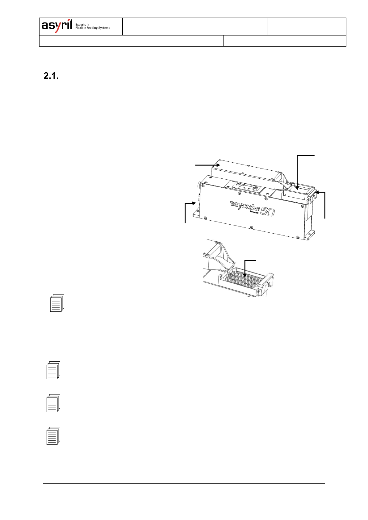
FIRST GLIMPSE AT THE PRODUCT.............................................................................................9
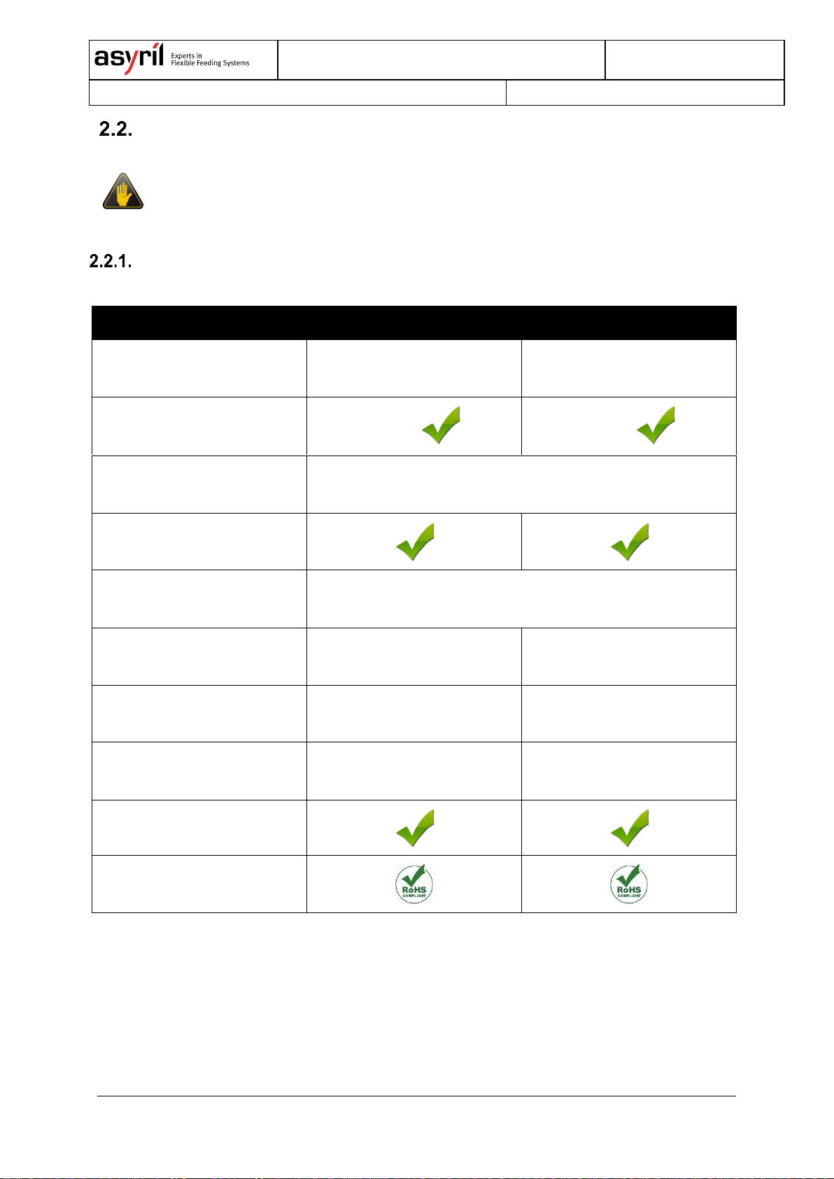
GENERAL CHARACTERISTICS.................................................................................................10
Technical features..............................................................................................................10
Overall dimensions.............................................................................................................11
Visual signals ......................................................................................................................13
Maximum permissible external force on the platform (Asycube 50 and 80)..............14
Permissible platform weight..............................................................................................14
Permissible hopper weight................................................................................................14
Maximum plate displacement...........................................................................................15
Plate Z repeatability ...........................................................................................................15
PERFORMANCE.......................................................................................................................16
Workspace (Picking surface)............................................................................................16
Displacement of the parts..................................................................................................16
ELECTRIC INTERFACES ..........................................................................................................17
Overview..............................................................................................................................17
Power connection...............................................................................................................18
Communication...................................................................................................................20
Backlight Synchronization.................................................................................................20
MECHANICAL INTERFACES .....................................................................................................21
Attachment of the Asycube...............................................................................................21
ACCESSORIES AND OPTIONAL MODULES...............................................................................22
Platform................................................................................................................................22
Platform with purge ............................................................................................................23
Special platform..................................................................................................................24
Hopper..................................................................................................................................28
Backlight ..............................................................................................................................29
Cables..................................................................................................................................29
3. TRANSPORTATION, HANDLING AND INSTALLATION.......................................................30
PACKAGING OF THE PRODUCT,TRANSPORTATION AND HANDLING .......................................30

Asycube 50 & 80
Operating Manual
© Copyright Asyril S.A.
000.100.501
Version: A1
000.100.501 Operating Manual - Asycube 50 & 80 3/45
UNPACKING INSTRUCTIONS....................................................................................................31
INSTALLATION AND STORAGE ENVIRONMENT.........................................................................32
Installation environment.....................................................................................................32
Storage environment..........................................................................................................32
4. MAINTENANCE AND REPARATION.........................................................................................33
SAFETY PRECAUTIONS...........................................................................................................33
General safety precautions...............................................................................................33
MAINTENANCE........................................................................................................................33
Periodic maintenance schedule .......................................................................................33
Remove the platform..........................................................................................................34
Exchange of the backlight.................................................................................................35
Recover IP address using default IP address................................................................37
Control and Cleaning of the platform...............................................................................39
REPARATION...........................................................................................................................40
TECHNICAL SUPPORT.............................................................................................................41
For better service …...........................................................................................................41
Contact.................................................................................................................................41
5. ANNEXES........................................................................................................................................42
CE CERTIFICATE....................................................................................................................42

Asycube 50 & 80
Operating Manual
© Copyright Asyril S.A.
000.100.501
Version: A1
000.100.501 Operating Manual - Asycube 50 & 80 4/45
1. Introduction
Generalities
The following document is the property of Asyril S.A. and may not be copied or circulated
without permission. The information contained in this document is subject to change without
notice for the purpose of product improvement. Before operating your product, please read
this document in order to ensure a correct use of the product. Nevertheless, if you meet
difficulties during the operation or the maintenance, please, feel free to contact Asyril
customer service.
In this manual, the safety precautions that you must respect are classified as: “Danger”,
“Warning” and “Note”; the following symbols are used :
DANGER!
Failure to observe the instruction may result in death or serious injury.
DANGER!
Failure to observe the instruction may result in electrocution or serious injury due to
electric shock
WARNING!
Failure to observe the instruction may result in injury or property damage.
NOTE :
The user should read carefully this information to ensure the correct use of the product,
although failure to do so would not result in injury.
REFER TO …
For more information on a specific subject, the reader should read other manual, or refer to
other paragraph.
WARNING!
Asyril shall not be liable whatsoever for any loss or damage arising from a failure to observe
the items specified in “Safety Precautions.” The customer is responsible to provide the
necessary instruction to the persons concerned.
NOTE :
All dimensions in this document are expressed in millimeters

Asycube 50 & 80
Operating Manual
© Copyright Asyril S.A.
000.100.501
Version: A1
000.100.501 Operating Manual - Asycube 50 & 80 5/45
Safety precautions
General safety precaution
Transport
DANGER !
Be aware of the weight and take care when transporting the system. For more
information, please refer to chapter 3 “Transportation, handling and installation”
General
DANGER !
Be sure that all power sources and other cables to the unit are disconnected before
working on the product.
DANGER !
Only qualified personnel (trained by Asyril and with professional experience) are
authorized to work on this device.
DANGER !
Do not unscrew the housing of the system controls. Serious injury or death could
result from electric shock. Only authorized personnel from Asyril SA are allowed to
access this part of the system for maintenance or for repair.
DANGER !
Do not plug or unplug cables of the system unless it is switched off.
DANGER !
Never modify the product. Unauthorized modification may cause the product to
malfunction, resulting in injury, electric shock, fire, etc.
DANGER !
Turn off the power to the product in the event of power failure. Failure to do so may
cause the product to suddenly start moving when the power is restored.
DANGER !
Do not use the product in a place where the main unit or controller may come in
contact with water or oil droplets.

Asycube 50 & 80
Operating Manual
© Copyright Asyril S.A.
000.100.501
Version: A1
000.100.501 Operating Manual - Asycube 50 & 80 6/45
Disposal
When the product becomes no longer usable or necessary, dispose of it properly as an
industrial waste.
WARNING!
Observe the valid legal regulation for appropriate disposal protecting environment.
Specific warnings
Safety Equipment for Operators
- For safety reasons operators must wear protective eyewear when using the backlight of the
Asycube without diffuser installed. (the backlight lighting LEDs is equivalent to a Class 1
compared with lasers)
For more information on visible or non visible radiation emitted by the backlight, please refer
to “1.2.2.2 Specific warnings concerning this product” on page 6.
NOTE :
It is the customer responsibility to install warning signs informing that anyone working around
the Asycube must wear safety equipment.
Specific warnings concerning this product
(A) Backlight
The Asycube has an integrated Backlight that
consists of LED’s (Light Emitting Diodes).
These LED’s emit visible or non-visible
radiation depending on the color of the
Backlight. LED’s illumination can create
discomfort od damage to cornea. Never look
directly into the light source without any
personal protection (e.g. protective eyewear).
Customers are encouraged to document their
unique application and instruct employees on
procedures to limit exposure to LED
radiation. This Backlight is not constructed to
be used permanently. Please switch off the
illumination after image acquisition. (Auto-
switch OFF after 30” of timeout)
Figure 1-1 :Specific warnings
concerning the Asycube

Asycube 50 & 80
Operating Manual
© Copyright Asyril S.A.
000.100.501
Version: A1
000.100.501 Operating Manual - Asycube 50 & 80 7/45
The used LED are class 0 according to the norm EN 62471. It is the responsibility of
customers to document their own application and instruct employees on procedures to limit
exposure to LED radiation. Following prevention agent can be suggested:
A. Interpose, insofar as the job allows, a high pass filter at x nm depending on the color (see
2.6.5) under a fixed or adjustable connection between the source and the employee
B. When the implementation of the foregoing is not possible, provide workers with goggles
or face shield suitable for blocking radiation beyond 700nm;
C. Prohibit or limit as possible direct access to the source (exposure in the axis of radiation).
D. Establish a security perimeter to prevent operators from approaching the source at
distances beyond the nominal ocular hazard recommended by the manufacturer
E. In all cases, ensure that the means used properly mitigate exposure variables
(characteristics of screens or goggles to choose based on wavelength which operators
are exposed).
Temperature
The active elements into the asycube
make the surfaces shown on the
picture heating up to 40°C in nominal
use. This temperature can
nevertheless increase to 55°C in
extreme use.
It is the responsibility of customers to
document their own application and
instruct employees on procedures to
avoid contact with these surfaces
Figure 1-2 :Specific warnings
Warranty information
You will find all the Asyril warranty information (duration, scope of warranty …) on the general
conditions of sale.
CE information
The declaration of incorporation as a partly completed machinery can be found here below.

Asycube 50 & 80
Operating Manual
© Copyright Asyril S.A.
000.100.501
Version: A1
000.100.501 Operating Manual - Asycube 50 & 80 8/45
NOTE:
The partly completed machinery (Asycube) must not be put into service until the final
machinery into which it is to be incorporated has been declared in conformity with provisions
of this directive, where appropriate.
Refer to“5.1 CE Certificate" on page 42 for the complete CE Certificate of the asycube.

Asycube 50 & 80
Operating Manual
© Copyright Asyril S.A.
000.100.501
Version: A1
000.100.501 Operating Manual - Asycube 50 & 80 9/45
2. Description
First glimpse at the product
Asycube sets new standards in miniature part feeding. Its 3D vibratory platform allows fast
and flexible presentation of miniature parts (0.2 mm to 8 mm) to a robot equipped with a
vision system. It consists in:
(A) A 3D vibrating platform (optional)
(B) A removable hopper where the
components are stored (optional)
(C) Electrical interfaces (communication,
power supply, I/Os…)
(D) An integrated mechanism allowing to
remove the platform easily without
additional tooling
(E) An integrated backlight (optional) that
allows an easy recognition of the
parts with a camera
For more information on electrical
interfaces to the Asycube, please
refer to “2.4. Electric Interfaces” on
page 17
Figure 2-1 : Asycube overview
For more information on how to remove or change the platform, please refer to ”4.2.2.
Remove the platform”on page 34
For more information on the procedure to control the platform and bulk vibrations, please
refer to the HMI manual
For more information on the backlight color and the procedure to exchange the backlight,
please refer to “4.2.3 Exchange of the backlight” on page 35
(B)
(A)
(C)
(D)
(E)

Asycube 50 & 80
Operating Manual
© Copyright Asyril S.A.
000.100.501
Version: A1
000.100.501 Operating Manual - Asycube 50 & 80 10/45
General Characteristics
WARNING !
Do not use the product outside the specifications. In cases of nonobservance the product
guarantee will expire.
Technical features
Asycube 50
Asycube 80
Typical part size
from 0.2 mm to 3 mm side
length
from 3 mm to 8 mm side length
Integrated LED backlight
Optional
Optional
Interchangeable backlight
color
(green, red, blue, white, infrared) please refer to “2.6.5 Backlight”
on page 29 for more information.
Independent vibrations in
three orthogonal directions
Interchangeable vibration
platform
Refer to section 4.2.2 for more information.
Vibration frequency
configurable
60 –100 Hz
60 –120 Hz
Maximum weight on the
platform (components)
50 g
50 g
Maximum weight on the
hopper (components)
400 g
400 g
Easily removable hopper
RoHS

Asycube 50 & 80
Operating Manual
© Copyright Asyril S.A.
000.100.501
Version: A1
000.100.501 Operating Manual - Asycube 50 & 80 11/45
Overall dimensions
Figure 2-2 : overall dimensions
Characteristic
Asycube 50
Asycube 80
Footprint (mm)
A
293
320
E
46
65
Platform height (mm)
B
118
119
Total height (mm)
C
140
140
Cables
D
50
50
Size of vibration
platform (mm)
F
34
52
G
45
65
Weight (kg)
3.1
3.7

Asycube 50 & 80
Operating Manual
© Copyright Asyril S.A.
000.100.501
Version: A1
000.100.501 Operating Manual - Asycube 50 & 80 12/45
Additional space is needed around the Asycube to unclamp and remove the platform with the
integrated lever:
Figure 2-3 : overall dimensions with "lever"
Characteristic
Asycube 50
Asycube 80
Lever footprint (mm)
K
140
140
L
15
12
Refer to “4.2.2 Remove the platform”on page 34 for more information on how to remove the
platform.

Asycube 50 & 80
Operating Manual
© Copyright Asyril S.A.
000.100.501
Version: A1
000.100.501 Operating Manual - Asycube 50 & 80 13/45
Visual signals
The LEDs give the following information on the state of
the Asycube :
LED
State
Meaning
Power
On
24V on Power input
S-power
On
24V on S-Power input (see
2.4.2 for more information)
Platform
On
Platform vibrating
Hopper
On
Hopper vibrating
State
Blinking
Time on : 100ms
System in standby
Blinking
Time on : 900ms
System in service
Backlight
On
24V on backlight
Synchronization input
1
On
Communication
Figure 2-4 : Asycube LED
indicator
(1)

Asycube 50 & 80
Operating Manual
© Copyright Asyril S.A.
000.100.501
Version: A1
000.100.501 Operating Manual - Asycube 50 & 80 14/45
Maximum permissible external force on the platform (Asycube 50 and 80)
The maximum permissible external
force on a point of the platform (for
example, with the gripper) is:
Fx = 3 N
Fy = 3 N
Fz = 5 N
Note that the shock/impact of the
gripper may damage the surface of
the platform.
Permissible platform weight
Asycube
50
Asycube
80
Maximum weight of the platform
(without components)
150 g
150 g
Maximum weight of components
(in addition to the maximum
weight of the platform)
50 g
50 g
Permissible hopper weight
Asycube
50
Asycube
80
Maximum weight of the hopper
(without components)
400 g
400 g
Maximum weight of components
(in addition to the maximum
weight of the hopper)
400 g
400 g

Asycube 50 & 80
Operating Manual
© Copyright Asyril S.A.
000.100.501
Version: A1
000.100.501 Operating Manual - Asycube 50 & 80 15/45
Maximum plate displacement
Asycube
50
Asycube
80
Maximum displacement x
±0.5mm
±0.5mm
Maximum displacement y
±0.5mm
±0.5mm
Maximum displacement z
±0.5mm
±0.5mm
Plate Z repeatability
Asycube
50
Asycube
80
Plate Z repeatability
±20 µm
±20 µm

Asycube 50 & 80
Operating Manual
© Copyright Asyril S.A.
000.100.501
Version: A1
000.100.501 Operating Manual - Asycube 50 & 80 16/45
Performance
Workspace (Picking surface)
The picking surface dimensions
corresponds to the Asycube platform
size :
Data
Asycube
50
Asycube
80
A
34 mm
52 mm
B
45 mm
65 mm
Figure 2-5 : Picking surface
Displacement of the parts
To define a specific movement with
the Asycube several parameters need
to be configured. For each movement
on the cube, twelve parameters must
be set. Calling these twelve
parameters will generate specific
vibrations (corresponding to the sum
of the movements of the three
actuators situated below the
platform).
The figure on the right shows the
predefined parameters and the
associated movements.
For more information on these
parameters, and to learn how to
configure them, in order to control the
cube and hopper vibrations, please
refer to the Asyril_ASYCUBE-
50_80_Programming_Guide
Figure 2-6 : predefined displacement of the parts
A
B

Asycube 50 & 80
Operating Manual
© Copyright Asyril S.A.
000.100.501
Version: A1
000.100.501 Operating Manual - Asycube 50 & 80 17/45
Electric Interfaces
Overview
The asycube is a standalone module
with its own controller. The electrical
interfaces are at the back of the
product:
(A) Power connection
(B) Ethernet connection (RJ45)
(C) Backlight synchronization
Figure 2-7 : Electrical interfaces to the Asycube
No cable are delivered with the Asycube, but can be ordered separately (please refer to the
chapter 2.6.6 “Cables”)
(A)
(B)
(C)

Asycube 50 & 80
Operating Manual
© Copyright Asyril S.A.
000.100.501
Version: A1
000.100.501 Operating Manual - Asycube 50 & 80 18/45
Power connection
WARNING !
- Before supplying power to the Asycube, check the nominal voltage.
- Ensure that the power cable is connected to the asycube before switching on
- Always turn off the power supply of the asycube before disconnecting the power
cable.
- Make sure to connect the 0V and the 24V according to the table. An incorrect
connection can damage the asycube.
Power
Signal description
(1)
24VDC PELV S-Power
(2)
0V GND S-Power
(3)
24VDC PELV Power
(4)
0V GND Power
(5)
EARTH
Connector type (on asycube side) :
M16, 5 Poles, male
In case of all functions working
simultaneously (vibration, backlight,
hopper), the current increases to 6A
Characteristic
Value
Voltage
+24V DC +
5%
Current Power
5 A max.
Current S-Power
1 A max.
Figure 2-8 : power connection
(1)
(2)
(3)
(4)
(5)

Asycube 50 & 80
Operating Manual
© Copyright Asyril S.A.
000.100.501
Version: A1
000.100.501 Operating Manual - Asycube 50 & 80 19/45
NOTE
S-Power is the safety power for the backlight. Cutting this S-Power ensures that the
backlight stays OFF (e.g. to secure IR backlight danger).
The following connection schematic shows the way to connect the Asycube depending if
your application requires using an external relay to ensure that the backlight is safely
switched off or not.
In any case, both “Power” and “S-Power” have to be supplied for using the backlight.
Figure 2-9
Power connection without safety relay
Figure 2-10
Power connection with safety relay
Note:
Both Power and S-Power can be connected to a single power supply or to two different
power supplies.
The 0 V power supply and the 0 V S-power supply are internally connected in the
asycube.
Backlight
ASYCUBE
0VDC
24VDC
0V Power
0V S-Power
24V S-Power
24V Power
0VDC
24VDC
Backlight
ASYCUBE
0V Power
0V S-Power
24V S-Power
24V Power
Safety relay
0VDC
24VDC
0VDC
24VDC

Asycube 50 & 80
Operating Manual
© Copyright Asyril S.A.
000.100.501
Version: A1
000.100.501 Operating Manual - Asycube 50 & 80 20/45
Communication
The communication with the Asycube is
established by a standard Ethernet
communication via RJ45 port (A)
Characteristic
Value
Default IP
address
192.168.127.254
Default subnet
mask
255.255.255.0
Port
4001
MAC address
Can be read by
ARP request
For more information on the procedure to
restore the default IP address, please see
chapter 4.2.4.
Figure 2-11 : Ethernet connection RJ45
Backlight Synchronization
A standard M8 three-pins female cable
enables to synchronize camera acquisition
and Asycube backlight illumination, it must
be connected as follows :
Pin
Signal
(1)
Not wired
(3)
0V GND
(4)
+24 V pulse
(illumination synch.)
Connector type (on asycube side) :
M8, 3P, male
Figure 2-12 : Backlight synchronization
NOTE :
The Asycube Backlight illumination time corresponds to the length of the pulse signal.
(A)
(1)
(4)
(3)
This manual suits for next models
1
Table of contents
Other Asyril Industrial Equipment manuals

Asyril
Asyril SmartSight Operating instructions

Asyril
Asyril Asycube Control URCap User manual

Asyril
Asyril Asycube 240 User manual

Asyril
Asyril Asycube Largo A5 User manual

Asyril
Asyril Asycube User manual

Asyril
Asyril Asycube 240 Operating instructions

Asyril
Asyril Asycube 380 User manual

Asyril
Asyril Asycube Series Instruction Manual

Asyril
Asyril Asycube Series User manual