Asyril SmartSight Operating instructions

SmartSight
Programming Guide
Document
SMARTSIGHT_Programming_Guide_EN
000.100.531
Version
C
Date
16.01.2018
Version SW
From
4.0.2
To


SmartSight - Asyril SA
Programming Guide
© Copyright Asyril S.A.
Introduction
Version: C
000.100.531 SmartSight - Programming Guide 3/31
Table of Contents
1. INTRODUCTION..............................................................................................................................................4
1.1. GENERAL INFORMATION...........................................................................................................................4
1.2. OTHER MANUALS......................................................................................................................................5
2. GENERAL INTRODUCTION............................................................................................................................6
2.1. OVERVIEW................................................................................................................................................6
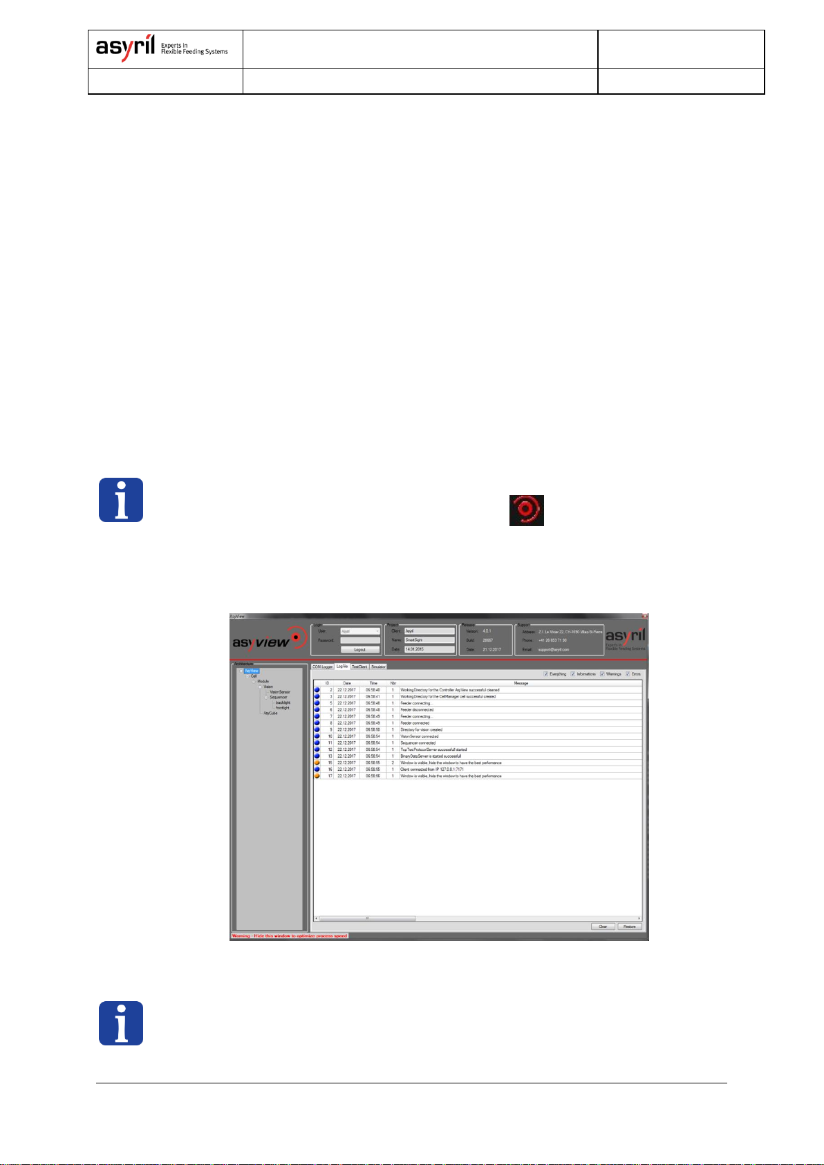
2.1.1. Asyview.......................................................................................................................................... 7
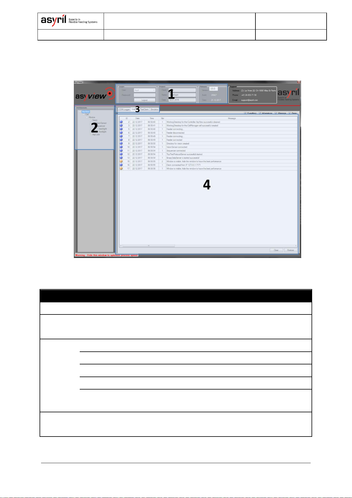
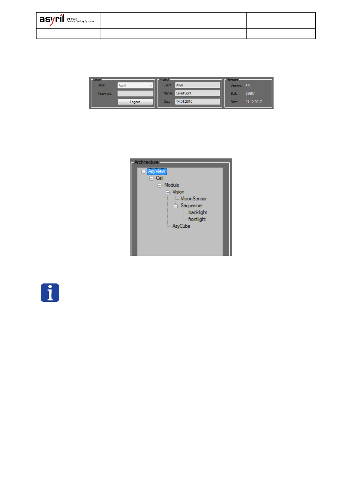
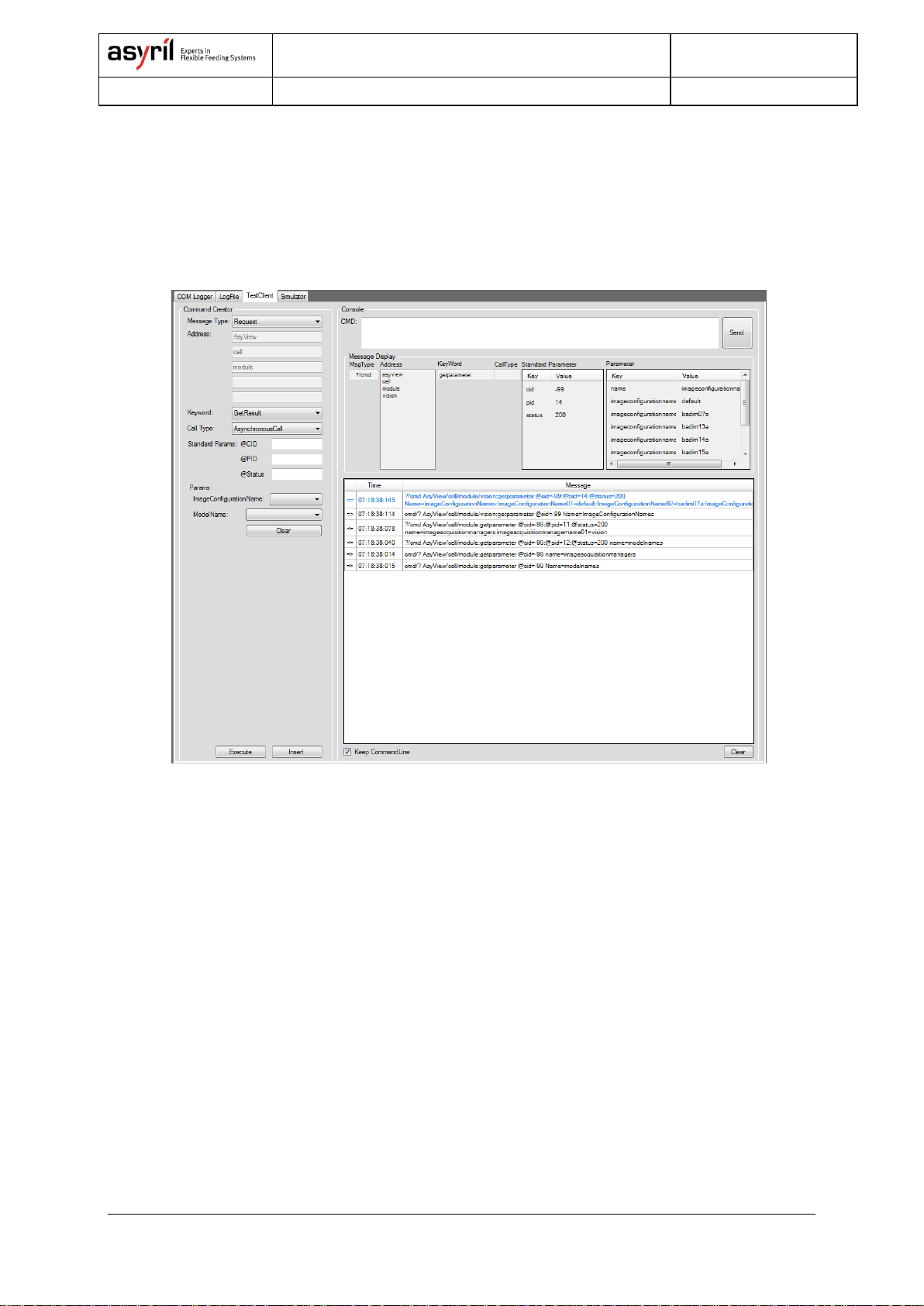
2.1.2. Asyview interface.......................................................................................................................... 7
2.1.3. Human Machine Interface –HMI ............................................................................................. 12
3. COMMUNICATION PROTOCOL...................................................................................................................13
3.1. TCP/IP PARAMETERS............................................................................................................................13
3.2. PROTOCOL.............................................................................................................................................13
3.2.1. Synchronous Mode .................................................................................................................... 14
3.2.2. Asynchronous Mode .................................................................................................................. 14
3.3. ARCHITECTURE AND ADDRESSING.........................................................................................................15
3.4. RESPONSE CODES.................................................................................................................................15
4. METHODS......................................................................................................................................................16
4.1. MODES ...................................................................................................................................................16
4.2. WORKING MODE....................................................................................................................................16
4.2.1. Active Working Mode................................................................................................................. 17
4.2.2. Passive Working Mode.............................................................................................................. 22
4.3. RECIPE...................................................................................................................................................23
5. INSTRUCTIONS.............................................................................................................................................24
6. TECHNICAL SUPPORT.................................................................................................................................29
6.1.1. For a better service … ............................................................................................................... 29
6.1.2. Contact......................................................................................................................................... 29
REVISION TABLE .................................................................................................................................................30

SmartSight - Asyril SA
Programming Guide
© Copyright Asyril S.A.
Introduction
Version: C
000.100.531 SmartSight - Programming Guide 4/31
1. Introduction
1.1. General information
This document is the property of Asyril SA; it may not be reproduced, modified or
communicated, in whole or in part, without our prior written authorization. Asyril SA reserves
the right to modify any information contained in this document for reasons related to product
improvements without prior notice. Before using the product, please read this entire
document in order to ensure that the product is used correctly. However, if you encounter
difficulties when using the product, do not hesitate to contact our customer service
department.
In this manual, the safety information that must be respected is split into three types:
"Danger", "Important" and "Note". These messages are identified as follows:
DANGER!
Failure to respect this instruction may result in serious physical injury.
DANGER!
This instruction identifies an electrical hazard. Failure to respect this instruction may
result in electrocution or serious physical injury due to an electric shock.
IMPORTANT!
Failure to respect this instruction may result in serious damage to equipment.
NOTE:
The reader's attention is drawn to this point in order to ensure that the product is used
correctly. However, failure to respect this instruction does not pose a danger.
Reference …
For more information on a specific topic, the reader is invited to refer to another manual or
another page of the current manual.
IMPORTANT!
Asyril cannot be held responsible for damage to property or persons caused by the failure to
respect the instructions contained in the manual for your machine.
NOTE:
All dimensions and values in this manual are expressed in millimeters (mm)

SmartSight - Asyril SA
Programming Guide
© Copyright Asyril S.A.
Introduction
Version: C
000.100.531 SmartSight - Programming Guide 5/31
1.2. Other manuals
The table below provides a list of documents supplied with the product. Each of these
manuals forms an integral part of the set of documentation associated with the product.
This manual contains a description of how the product works and information on
communication and using the product in programming.
Manual title
Reference
Description of the content
Operating
Manual
SMARTSIGHT_Operating_Manual_EN
SMARTSIGHT_Manuel_Instructions_FR
SMARTSIGHT_Bedienungsanleitung_DE
Contains a technical
description of the product,
its functionalities and
provides maintenance and
transport information
concerning the product
HMI Manual
Describes how to use the
HMI, directly accessible via
the HMI
Programming
Guide
SMARTSIGHT_Programming_Guide
THIS MANUAL
User Guide
SMARTSIGHT_User_Guide_EN
SMARTSIGHT_Manuel_Utilisation_FR
SMARTSIGHT_Benutzhandbuch_DE
Contains information about
how to use and configure a
new recipe (feeding and
vision recognition)
Table 1-1: Other manuals

SmartSight - Asyril SA
Programming Guide
© Copyright Asyril S.A.
General introduction
Version: C
000.100.531 SmartSight - Programming Guide 6/31
2. General introduction
SmartSight describes Asyril’s intelligent visual part detection system, ensuring straightforward
integration of any Asycube flexible feeder with any industrial robot brand. SmartSight
comprises Asyril’s powerful visual part detection and feeder management software, an
industrial PC as well as an optimally configured Asycube and vision kit including camera,
objective and all necessary cabling. It makes the implementation of high performance flexible
feeding system as simple as setting up conventional feeders.
Capable of controlling up to 4 cameras and feeders, SmartSight is able to control the part
movements, ensuring their optimal separation and distribution on the platform. The location of
the parts to be picked is then provided to the robot or industrial controller. The system can be
easily programmed thanks to Asyril’s intuitive user interface.
Alternative configurations for functionalities such as control part presence, position in gripper,
placing position are available on demand.
This document describes the function and operation of the SmartSight and its software
interfaces and the various functions involved in its use and integration.
For information about the hardware configuration and setup, please refer to SmartSight
Operating Manual.
2.1. Overview
The SmartSight software is called Asyview. It has an interface dedicated to the integrator
tasks as well as some log functionalities available for the end-user. The configuration of any
recipes and calibration tasks is operated through the Asyril HMI.
Role
Asyview
Visual part detection and feeder management
Asyview interface
Monitoring and support to the integration
HMI
Interface for monitoring, configuring and teaching new recipe
Table 2-1: role of Asyview and interfaces

SmartSight - Asyril SA
Programming Guide
© Copyright Asyril S.A.
General introduction
Version: C
000.100.531 SmartSight - Programming Guide 7/31
2.1.1. Asyview
The vision system manages the recognition of components and their location based on
criteria and models configured using the human-machine interface (HMI). Using a camera
placed above an Asycube feeding system, the distribution state of the components is
analysed by the Asyview, allowing it to automatically manage the movements on the
Asycube.
These configurations are saved in the form of a recipe for each type of component. This
includes:
- the different parameters linked to the Asycube,
- the image and lighting acquisition levels
- the vision model that enables the components to be located and the adapted exclusion
zone.
2.1.2. Asyview interface
NOTE:
Asyview interface can be launched by right clicking on the logo on the icon bar
At starting the Asyview interface is automatically logged with the end-user access level
(Figure 2-1). It allows showing the last entries of the Log File and informs also about the
installed release and architecture configured.
Figure 2-1: Asyview interface
NOTE:
To optimize the process speed, make attention to hide the Asyview interface window. A factor
of 10x could be won by closing this window.

SmartSight - Asyril SA
Programming Guide
© Copyright Asyril S.A.
General introduction
Version: C
000.100.531 SmartSight - Programming Guide 8/31
Once logged on, you will have access to different tags function as shown in Figure 2-2 and
Table 2-2.
Figure 2-2: structure of the Asyview interface
Asyview interface
Contents
1
Information (Figure 2-3)
Login, project description and software release information
2
Architecture (Figure 2-4)
Architecture of the SmartSight
Allow accessing to each of the different levels
3
Tabs
COM Logger
when checked, show all sent/received commands
LogFile
monitor and save all messages
TestClient
description and structure of all commands
Simulator
simulates the whole process with vision detection, feeding
management and pick&place
4
Tabs content
Content will depends on the selected tabs
with export/clear/execute action buttons
Table 2-2: Asyview interface content

SmartSight - Asyril SA
Programming Guide
© Copyright Asyril S.A.
General introduction
Version: C
000.100.531 SmartSight - Programming Guide 9/31
By default the interface is logged as end-user (no password). Integrator level allows
accessing all functionalities. Integrator password is “1234”.
Figure 2-3: Connection and project information on Asyview interface
By selecting a level in the architecture section (Figure 2-4), the information showed in the tab
content will be filtered to show only the corresponding message or commands.
Figure 2-4: Architecture of the SmartSight with access to the different levels
NOTE:
Asyril is responsible for the SmartSight architecture configuration, which serves as a specific
encryption based on the customer's requirements.

SmartSight - Asyril SA
Programming Guide
© Copyright Asyril S.A.
General introduction
Version: C
000.100.531 SmartSight - Programming Guide 10/31
Depending on the selected architecture level, the TestClient tab will list all corresponding
and available commands (Chapter 5 “Instructions”). It can help then to build a command by
selecting and informing the keywords and parameters. By clicking on the Insert button the
complete command will be written on the console and when selecting a message, the
commands is displayed in a more intuitive and readable format.
Figure 2-5: TestClient tab

SmartSight - Asyril SA
Programming Guide
© Copyright Asyril S.A.
General introduction
Version: C
000.100.531 SmartSight - Programming Guide 11/31
In the Simulator tab one can launch a cycle with the simulated pick requested. It allows
testing and seeing how to implement the process and the synchronization between the
(robot) controller and the SmartSight controller. The different parameters allow to set some
timer and to follow the results. Please note that a vision configuration has to be done before
starting the simulation.
Figure 2-6 : Simulator tab

SmartSight - Asyril SA
Programming Guide
© Copyright Asyril S.A.
General introduction
Version: C
000.100.531 SmartSight - Programming Guide 12/31
2.1.3. Human Machine Interface –HMI
The Asyril HMI (Figure 2-7) is dedicated to the vision and feeding configuration. It encloses
also some other more general functionalities. See the general presentation in Table 2-3.
End-User
Integrator
General
Load and save recipes
Monitoring of state and alarms
Management of the user accounts
Vision
Teach new parts
Acquire a new image and get/show the
corresponding results
Prepare the system :
- adjust the camera position (live)
- define the image configuration
Run the different calibrations
Feeding
Optimize the feeder parameters
Optimize the process to feed the parts
Table 2-3: HMI Functionalities
Figure 2-7: Asyril HMI on the vision home results tab
For more information, refer to the HMI Manual (also available directly on the interface by
clicking on the button) or to the User Guide to teach new parts and to create recipes.

SmartSight - Asyril SA
Programming Guide
© Copyright Asyril S.A.
Communication
protocol
Version: C
000.100.531 SmartSight - Programming Guide 13/31
3. Communication protocol
3.1. TCP/IP parameters
The Asyview is implemented like a TCP/IP server operating as a slave to the machine. You
will therefore need to implement a TCP Client to connect to the Asyview.
The default configuration for the Asyview server port (PROCESS) is as follows:
IP address
Subnet Mask
Port
192.168.0.70
255.255.255.0
7171
Table 3-1: Asyview PROCESS TCP/IP parameters
3.2. Protocol
Here below is the general description of the protocol, followed by the different response
modes available.
Figure 3-1: Protocol description
- Message Type (MsgType) indicates if this is a request or a response message
- The command is built in 3 parts :
oThe address where the command should apply (see chapter about the
architecture for more information)
oThe Keyword is the name of the function or action to apply
oThe command type (CmdType) indicates the response mode to use
- The standard parameters are common to all functions and correspond to
oCID (Call Identifier) can be freely defined by the caller or used to differentiate the
caller
oPID (Process Identifier) is a unique internal identifier given by the Asyview. It can
be used to ask the state of a command or to match request and response
oStatus: indicate the status of the command following the http standard response
codes.
- Parameters: they are specific to each command.
- Each message ends with CRLF.

SmartSight - Asyril SA
Programming Guide
© Copyright Asyril S.A.
Communication
protocol
Version: C
000.100.531 SmartSight - Programming Guide 14/31
3.2.1. Synchronous Mode
In this mode, the commands are blocking. The request will launch the corresponding action.
The response message is then synchronized with the end of the executed action. The call
can thus be short or long depending on the request.
This is the default mode.
Figure 3-2: short and long call on synchronous mode
3.2.2. Asynchronous Mode
The request will launch the corresponding action. The first response indicates if the validation
was successful or not. In the first case, the system will send a callback when the execution is
finished (error / success / result). If necessary, it is possible to ask about the status of the
executed action by query with the command type “/?” and the corresponding PID.
The associated command types for the asynchronous mode are:
- Asynchronous Call: “/!”
- Asynchronous Query (interrogation): “/?”
- Asynchronous CallBack: “/#”
Figure 3-3: Asynchronous mode with and without interrogation of the status.

SmartSight - Asyril SA
Programming Guide
© Copyright Asyril S.A.
Communication
protocol
Version: C
000.100.531 SmartSight - Programming Guide 15/31
3.3. Architecture and addressing
The Asyview is structured in a way allowing building different configurations of feeders and
cameras that could work independently. Figure 3-4 shows the generic architecture of the
Asyview.
Figure 3-4: Architecture level of the Asyview
There are 2 ways of addressing the different level:
1. With the name of each level. For example : “AsyView/CellLeft/Module/Vision”
2. With the index. For example : ”a[0[/c[0]/m[0]/i[0]”
3.4. Response codes
Code
Name
Comment
100
Continue
102
Processing
Use to query Asynchronous call
200
OK
400
Bad Request
404
Invalid Request
405
Not Allowed Request
406
Duplicated Request
Additional message sent but only one can be treated at a time
498
Error
Generic error
501
Not Implemented
505
Not Supported
Polling
Table 3-2: listing of the response codes

SmartSight - Asyril SA
Programming Guide
© Copyright Asyril S.A.
Methods
Version: C
000.100.531 SmartSight - Programming Guide 16/31
4. Methods
4.1. Modes
The Asyview controller has two modes: Configuration and Process. Their functions are as
follows:
- Configuration:
oDefault mode
oAllows recipes to be created and modified
Adjusting image and lighting acquisition sequences
Teaching vision models
Adjusting Asycube parameters
Selecting the operating mode
oLoading and saving recipes
oCalibration (calculation)
- Process:
oActive mode: once this state is reached, the system launches the cycle to obtain
the first available component (feeding by Asycube, then acquiring an image as
soon as the field of view is unlocked)
oPassive mode: the system is ready to receive image and then position requests.
The Start and Stop commands are used to switch from one mode to another.
Each module can be switched independently from one state to another. This means that one
camera can be in configuration mode while a process is under way on another module.
Below are descriptions of the different usage methods concerning the Active and Passive
Process, as well as the various calibration procedures for calibrating the fields of view.
All the instructions are listed in chapter 5.
4.2. Working Mode
There are two types of operation. The main difference between them is whether the feeder
has to be automatically managed or not.
A distinction can therefore be made between the uses of
- a camera placed above an Asycube to prepare a list of available parts in order to send
their position once the request is made,
- a control camera whose image acquisition is subject to a request (e.g. by moving the
manipulator into the control field of view).

SmartSight - Asyril SA
Programming Guide
© Copyright Asyril S.A.
Methods
Version: C
000.100.531 SmartSight - Programming Guide 17/31
Their main characteristics are as follows:
- Active mode:
oautomatic management of the Asycube and image acquisition using information
concerning synchronization with the pick & place process
oautomatic “feeding cycle –image acquisition –data processing” sequence until a
result is obtained
oduring a position request: sending of the position of the first available part, even if
the image analysis is not complete
ocamera/lighting synchronization
- Passive mode:
oimage acquisition on request
ocamera/lighting synchronization
ono Asycube management
4.2.1. Active Working Mode
Figure 4-1 shows the standard interaction between a SmartSight module and the machine to
synchronize the two cycles and transfer the position information.
Reminder: in the Active type, the Asyview manages the Asycube feeding system
automatically. This means that, when an image is being processed, an initial step is executed
to deliver the positions of the available parts as quickly as possible based on the configured
criteria. These positions can be read even if the image processing is not complete, to enable
the Pick&Place operations to be started as soon as possible. In the second step, once all the
possible positions have been detected, the system evaluates also the distribution of the
components on the surface of the Asycube to generate the appropriate vibration sequence. It
is then ready to launch the feeding sequence as soon as all the positions have been deleted.
The simulator (Asyview interface) details the same method and describes the instructions
used and the responses obtained.
There is a possibility to force the system to take a new picture before every pick. To do that,
send a command to clear all the results after placing the part (see Figure 4-1). This can be
useful when the position of the parts that are still on the platform may change between two
picks because of an external perturbation (for example: parts move while picking another
one, vibration of the overall system is inducing movement of parts on the platform).
In the following diagrams, the red boxes are action with communication with Asyview.

SmartSight - Asyril SA
Programming Guide
© Copyright Asyril S.A.
Methods
Version: C
000.100.531 SmartSight - Programming Guide 18/31
4.2.1.1. With only one model
Start Vision Device
Set Working Mode to Active
Robot is out of the
field of view
Free field of view
Part pick and
place loop
Position request
Block field of view
Robot picks part
Remove position
from list
Robot leaves field of
view
Free field of view
Robot places parts
No
Stop
End of cycle
Need new
picture ?
Take a new picture
Yes
Working mode has to be
defined once for each
module
Asyview switches from
Configuration to Process
mode
From this point, Asyview
can take a picture and
feed parts if no part is
available.
A result is given as soon
as the first correct part
has been found. Image
processing will then
continue to prepare the
next results and the next
feeding movements
Asyview can no longer
take a picture (the robot
will enter the field of
view)
From this point, and if
necessary because the
position list is empty,
the system can feed
(vibrate)
From this point, the
system can take a
picture (and continue to
feed if necessary)
Asyview switches from
Process to Configuration
mode
Asyview forces the
system to capture a new
picture
Figure 4-1: Schematic of the Active mode with one model

SmartSight - Asyril SA
Programming Guide
© Copyright Asyril S.A.
Methods
Version: C
000.100.531 SmartSight - Programming Guide 19/31
4.2.1.2. With many models, without choosing the part to take
This mode of production is for example when you have 2 parts on the same surface and you
want to take all the parts independently of the order.
Start Vision Device
Set Working Mode to Active
Robot is out of the
field of view
Free all field of view
Part pick and
place loop
Position request
Block fields of view
impacted
Robot picks part
Remove position
from list
Robot leaves field of
view
Free field of view
impacted
Robot places parts
No
End of cycle
Stop
Need new
picture ?
Take a new picture
Yes
Working mode has to be
defined once for each
module
Asyview switches from
Configuration to Process
mode
From this point, Asyview
can take a picture and
feed parts if no part is
available.
A result is given as soon
as the first correct part
has been found. Image
processing will then
continue to prepare the
next results and the next
feeding movements
Asyview can no longer take a picture (the
robot will enter the field of view). Block
all fields of view which are obstructed by
the robot.
From this point, and if
necessary because the
position list is empty,
the system can feed
(vibrate)
From this point, the system can take a
picture (and continue to feed if
necessary). Release all fields of view
locked before.
Asyview switches from
Process to Configuration
mode
Asyview forces the
system to capture a new
picture
Figure 4-2: Schematic of the Active mode with many models, pick all parts

SmartSight - Asyril SA
Programming Guide
© Copyright Asyril S.A.
Methods
Version: C
000.100.531 SmartSight - Programming Guide 20/31
4.2.1.3. With many models, with choosing the part to take
This mode of production is for example when you have 2 parts on the same surface and you
want to take the parts in a specified order.
Start Vision Device
Set Working Mode to Active
Robot is out of the
field of view
Free all field of view
Part pick and
place loop
Position request
Block fields of view
impacted
Robot picks part
Remove position
from list
Robot leaves field of
view
Free field of view
impacted
Robot places parts
No
Stop
End of cycle
Need new
picture ?
Take a new picture
Yes
Working mode has to be
defined once for each
module
Asyview switches from
Configuration to Process
mode
From this point, Asyview
can take a picture and
feed parts if no part is
available.
A result is given as soon
as the first correct part
has been found. Image
processing will then
continue to prepare the
next results and the next
feeding movements
Asyview can no longer take a picture
(the robot will enter the fields of
view). Block all fields of view which
are obstructed by the robot.
From this point, and if
necessary because the
position list is empty,
the system can feed
(vibrate)
From this point, the system can take
a picture (and continue to feed if
necessary). Release all fields of view
locked before.
Add indication for the requested part in the command
(ModelName or ImageConfigurationName)
Add indication for the next requested part in the command
(NextModelName or NextImageConfigurationName)
Asyview switches from
Process to Configuration
mode
Asyview forces the
system to capture a new
picture
Figure 4-3: Schematic of the Active mode with many models, pick specified part
Other manuals for SmartSight
4
Table of contents
Other Asyril Industrial Equipment manuals

Asyril
Asyril Asycube User manual

Asyril
Asyril Asycube 50 User manual

Asyril
Asyril Asycube 240 User manual

Asyril
Asyril Asycube Control URCap User manual

Asyril
Asyril Asycube 240 Operating instructions

Asyril
Asyril Asycube Series Instruction Manual

Asyril
Asyril Asycube Largo A5 User manual

Asyril
Asyril Asycube 380 User manual

Asyril
Asyril Asycube Series User manual