Asyril Asycube Series Instruction Manual

Asycube mechanical
integration guidelines
Document
Asycube mechanical integration guidelines
000.103.437
Version
A
Date
22.01.2020

Asycube mechanical integration guidelines
000.103.437
Version : A
2/14
Table of contents
1. INTRODUCTION...............................................................................................................................3
GENERAL INFORMATION...........................................................................................................3
DOCUMENT PURPOSE...............................................................................................................3
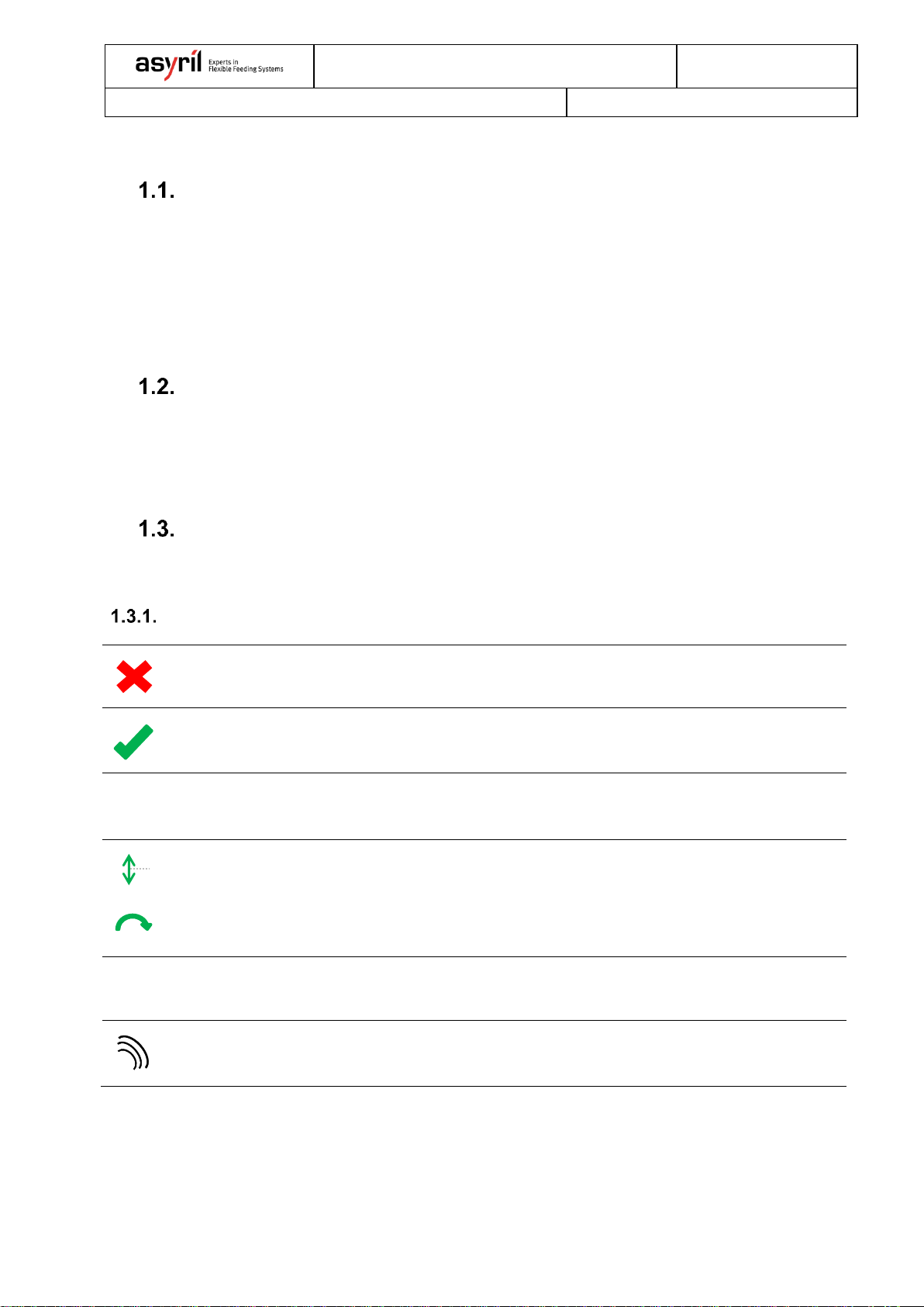
SYMBOLS..................................................................................................................................3
Images....................................................................................................................................3
Acronyms...............................................................................................................................4
2. ASYCUBE INTEGRATION .............................................................................................................5
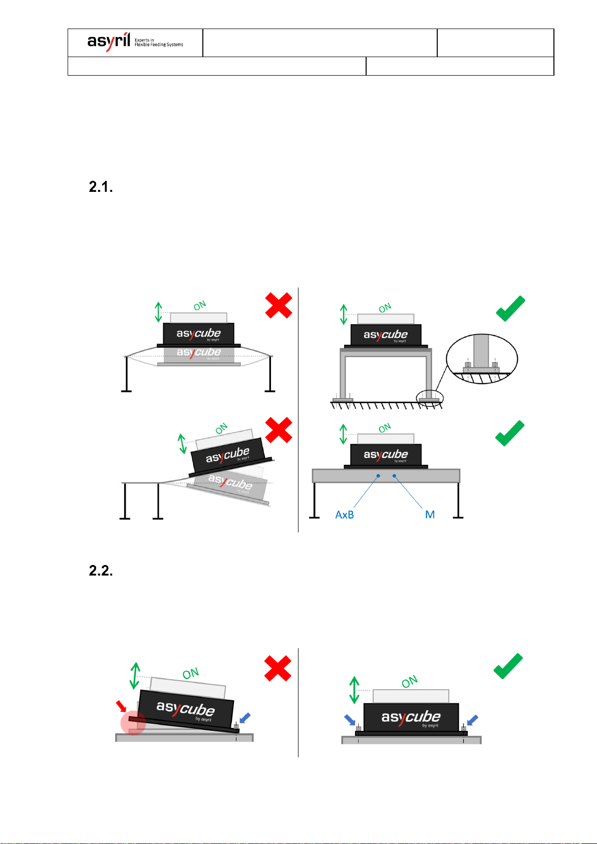
ASYCUBE POSITION ON SUPPORT AND SUPPORT CHARACTERISTICS......................................5
FIXING THE ASYCUBE ON ITS SUPPORT ...................................................................................5
3. VIBRATION DECOUPLING............................................................................................................6
DECOUPLING OF MOVING DEVICES ..........................................................................................6
DECOUPLING OF THE CAMERA .................................................................................................8
4. MINIMAL DISTANCE BETWEEN ASYCUBE(S)........................................................................9
5. TECHNICAL DATA TABLES.......................................................................................................10
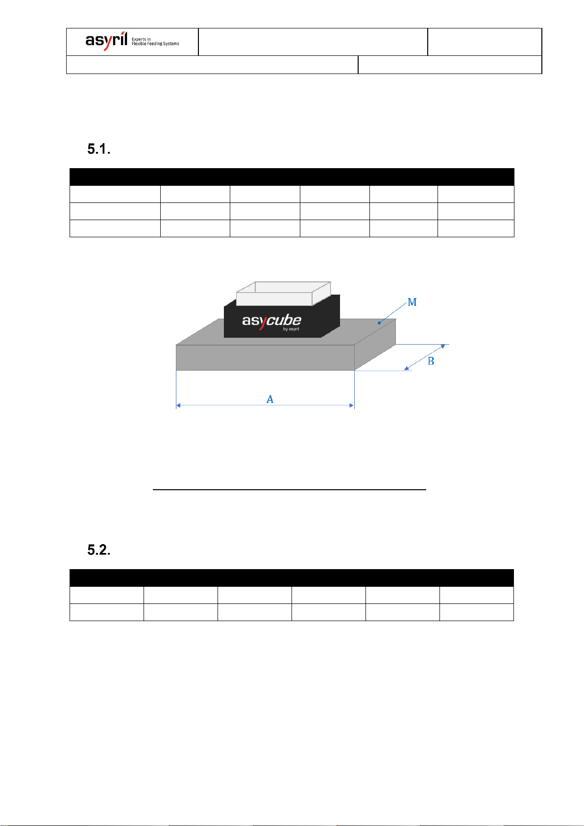
SUPPORT CHARACTERISTICS.................................................................................................10
SCREWS DETAIL .....................................................................................................................10
VIBRATION ISOLATORS DETAILS.............................................................................................11
MINIMAL DISTANCE BETWEEN ASYCUBE(S)...........................................................................12

Asycube mechanical integration guidelines
000.103.437
Version : A
3/14
1. Introduction
General information
The following document is the property of Asyril S.A. and may not be copied or circulated
without permission. The information contained in this document is subject to change without
notice for product improvement purpose. Please read this document carefully to ensure your
product correctly integrated and implemented. Nevertheless, should you encounter difficulties,
please contact Asyril customer service.
Document purpose
The main purpose of present document is to make machine manufacturers aware of the
different features necessary to ensure the correct integration of the Asycube product and its
accessories.
Symbols
Following symbols will be used multiple times in the document.
Images
Wrong implementation
Correct implementation
ON
Active / operating feature (moving)
Movements
OFF
Passive / NOT operating feature (NOT moving)
Perturbation / undesired vibration

Asycube mechanical integration guidelines
000.103.437
Version : A
4/14
Acronyms
APSO
Angst + Pfister - www.apsoparts.com –(section: Antivibration Technology; APSOvib)
A
max. support length for Asycube
B
max. support width for Asycube
c
distance between Asycube(s)
ØD
diameter of the round buffer APSOvib
H
height of the round buffer APSOvib
cz
spring constant of the round buffer APSOvib; compression in Z direction (axial direction)
Fz
max. allowed compressive force of the round buffer APSOvib
M
mass (used for Asycube feature definition)
N/A
not applicable
Qty.
quantity
Ref.
reference

Asycube mechanical integration guidelines
000.103.437
Version : A
5/14
2. Asycube integration
Toensure good vibration behavior the Asycube must be correctly fixed on a support specifically
defined for the application. An incorrect installation of the Asycube could compromise the
performances of the product.
Asycube position on support and support characteristics
The Asycube must be fixed either on a rigid support screwed to the ground or on a "free" heavy
support. For the second application the mass [M] and the dimensions [AxB] of the support must
be large enough to absorb the vibrations generated by the feeder. These mass and dimensions
are summarized in: Table 5-1 - Support characteristics.
Fixing the Asycube on its support
The Asycube must be properly screwed on the support. The quantity of screws necessary to
fix the base plate of the Asycube and the screws dimensions are summarized in: Table 5-2 -
Screws detail.

Asycube mechanical integration guidelines
000.103.437
Version : A
6/14
3. Vibration decoupling
Incorrect assembly of Asycube(s), camera(s), robot(s) and hopper(s) may compromise final
system performance. To ensure the good behavior of a system, it is necessary to avoid that all
the involved devices can interfere with each other.
Note: hoppers provided by Asyril are already equipped with vibration isolators so that
hopper vibration is not transmitted to other peripherals.
Decoupling of moving devices
If several moving devices have to be assembled in parallel, and close to each other, it is
necessary to "decouple the vibrations", to avoid that behavior of any product is disturbed by
the movement of others.

Asycube mechanical integration guidelines
000.103.437
Version : A
7/14
To avoid backfeeding of vibrations it is therefore recommended to provide specific support for
each device. When this solution is not applicable, vibration decoupling can be achieved through
anti-vibration technologies (e.g. vibration isolators [①]).
Note: vibration isolators solution is only applicable to Asycube(s) 240, 380 and 530.
The mass [M] and dimensions [AxB] of the support are summarized in: Table 5-1 - Support
characteristics.
The vibration isolator [①] details are summarized in: Table 5-3 –Vibration isolators details.
Note: Increase the mass of the base support to avoid the integration of the vibration
isolators does not ensure that the spread vibrations will be completely dampen-out.

Asycube mechanical integration guidelines
000.103.437
Version : A
8/14
Decoupling of the camera
It is important that the camera is not perturbed by the vibration of Asycube or by any other
moving device. If the vision system is “disturbed”by residual vibrations, the coordinates sent
to the robot will not be reliable, thus compromising the precision of the whole system.
Therefore, it is recommended not to install Asycube(s) and camera on the same support. When
this solution is not applicable, be sure to fix the camera on a rigid and heavy enough support
to prevent back-feeding of vibrations into surrounding devices.

Asycube mechanical integration guidelines
000.103.437
Version : A
9/14
4. Minimal distance between Asycube(s)
If two or more Asycube(s) are installed close to each other, the movement of the active device
can excite the passive one. It is therefore recommended to install the Asycube(s) at enough
distance [c] to prevent them from disturbing each other.
The minimal distance [c] between Asycube(s) is summarized in: Table 5-4 - Distance between
Asycube(s).

Asycube mechanical integration guidelines
000.103.437
Version : A
10/14
5. Technical data tables
This chapter contains the technical parameters necessary to correctly install Asycube products.
Support Characteristics
Asycube
50
80
240
380
530
M –[Kg]
≥ 10
≥ 10
≥ 40
≥ 200
≥ 250
A –[mm]
≤ 600
≤ 600
≤ 600
≤ 1000
≤ 1200
B –[mm]
≤ 150
≤ 150
≤ 350
≤ 500
≤ 750
Table 5-1 - Support characteristics
Note: The thickness of the support must be calculated basing on requirements resumed in
Table 5-1 - Support characteristics.
Make sure that the minimal mass [M] requirement is respected.
Screws detail
Asycube
50
80
240
380
530
Qty. of screws
2
4
4
4
4
Screw Ø
M5
M5
M6
M8
M8
Table 5-2 - Screws detail

Asycube mechanical integration guidelines
000.103.437
Version : A
11/14
Vibration isolators details
①–Vibration isolator (round buffer; DIN 95363)
Asycube
240
380
530
APSO Ref. *1
12.2034.0103
12.2034.0293
12.2034.0353
ØD –[mm]
16
40
50
H –[mm]
20
40
50
cz–[N/mm]
50
180
190
Fz–[N]
120
690
1000
Qty. –[-]
4
4
4
Table 5-3 –Vibration isolators details
Attention:
Make sure that total mass of Asycube, support and components will not exceed the max. allowed
compressive force of the round buffers [Fz]. If this scenario occurs new round buffers must be
selected.
Vibration isolator (round buffer) details:
Vibration isolator (round buffer) positioning:
----------------------------------------------------------------------------------------------------------------------------------------
*1Angst + Pfister - www.apsoparts.com –(section: Antivibration Technology; APSOvib)

Asycube mechanical integration guidelines
000.103.437
Version : A
12/14
Minimal distance between Asycube(s)
Asycube
50
80
240
380
530
c –[mm]
≥ 10
≥ 10
≥ 10
≥ 30
≥ 30
Table 5-4 - Distance between Asycube(s)

Asycube mechanical integration guidelines
000.103.437
Version : A
13/14
Revisions:
Rev.
Date
Author
Comments
A
22.01.2020
SoD
First version

This document is the property of Asyril S.A. and may not be copied or circulated without
permission. The information contained in this document is subject to change without notice for
the purpose of product improvement.
asyril sa
z.i. le vivier 22
ch-1690 Villaz-st-pierre
Suisse
tél. +41 26 653 71 90
www.asyril.com
Other manuals for Asycube Series
2
This manual suits for next models
5
Table of contents
Other Asyril Industrial Equipment manuals

Asyril
Asyril Asycube 50 User manual

Asyril
Asyril Asycube 380 User manual

Asyril
Asyril Asycube Series User manual

Asyril
Asyril Asycube 240 User manual

Asyril
Asyril Asycube User manual

Asyril
Asyril SmartSight Operating instructions

Asyril
Asyril Asycube Control URCap User manual

Asyril
Asyril Asycube Largo A5 User manual

Asyril
Asyril Asycube 240 Operating instructions