Troubleshooting
Symptom
Possible Causes Possible Solutions
After pressing ■ Battery is not charged ■ Place handset in charging
[
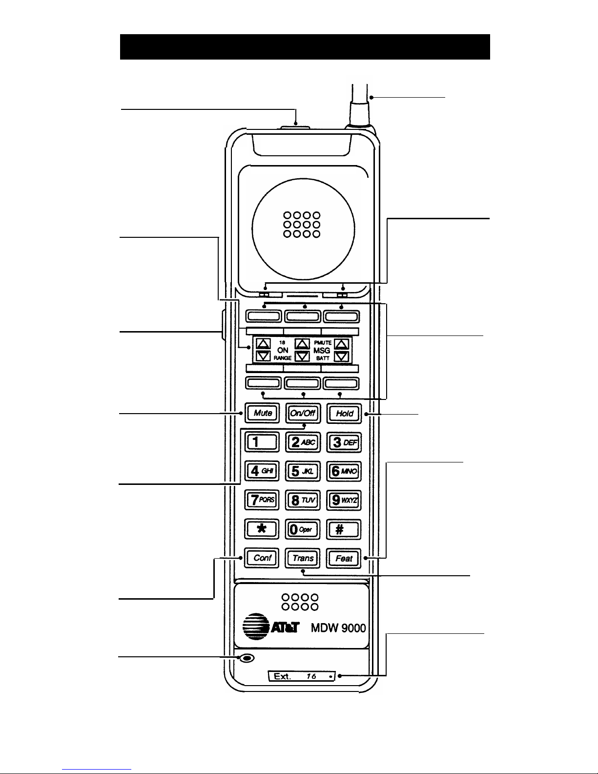
On/Off
], dial tone i
S
sufficiently.
cradle for 12 hours. Or, if
not heard and hand-
you have a fully charged
set display does not
(14 hours) spare battery,
show anything.
use it to replace the battery
in the handset.
■
Handset is out of range of
■ Move the handset closer
its matching radio module.
to the radio module.
■
Telephone line cord is not
■ Plug the telephone line
plugged into the radio
cord into the radio module.
module.
After pressing [
On/Off
],
■
There is no battery in the
■ Insert battery in handset.
dial tone is not heard handset.
and the
RADIO
LED
on the radio module
■ Battery is not inserted
■
Make sure battery is inserted
does not light.
properly in handset.
properly in handset.
■ Battery is not charged ■ Place handset in charging
sufficiently.
cradle for 12 hours. Or, if
you have a fully charged
(14 hours) spare battery,
use it to replace the
battery in the handset.
■
Handset is out of range of
■ Move the handset closer
its matching radio module.
to the radio module.
■
There is interference from
■
Remove electrical device
another electrical device causing interference or move
(microwave) or metal walls.
handset to another location.
BATT
appears in the Battery requires recharging.
You have 1-2 minutes of talk
handset display. time left. Either:
■
Complete your call, turn the
handset off, and recharge
the battery (12 hours).
■
If you have a fully charged
(14 hours) spare battery,
place your call on Hold.
Swap the batteries. Wait 6
to 10 seconds, then turn the
handset on and proceed as
you would for any call
placed on Hold.
5