AT&T MERLIN MAIL User manual

AT&T
999-510-137
Issue 1, July 1990
MERLIN MAIL
™
VOICE MESSAGING SYSTEM
Installation and
Implementation Guide
for MERLIN® II
Communications System
Release 3

©1990 AT&T
Issue 1
All Rights Reserved July, 1990
Printed in USA
NOTICE
The information in this document is subject to change without notice. AT&T
assumes no responsibility for any errors that may appear in this document.
MERLIN is a registered trademark of AT&T.
MERLIN MAIL is a trademark of AT&T.
Phillips is a registered trademark of the Phillips Screw Company.
The MERLIN MAIL™ Voice Messaging System is not
intended for use with the MERLIN II Attendant.

FCC Notification and Repair Information
This equipment is registered with the Federal
Communications Commission (FCC) in accordance with
Part 68 of its rules. In compliance with those rules, you are
advised of the following:
MEANS OF CONNECTION:
Connection to the
telephone network shall be through a standard network
interface jack USOC RJ11C. These USOCs must be
ordered from your Telephone Company.
This equipment may not be used with party lines or
coin telephone lines.
NOTIFICATION TO THE TELEPHONE COMPANIES:
Before connecting this equipment, you or your equipment
supplier must notify your local telephone company’s
business office of the following:
The telephone numbers you will be using with this
equipment.
The appropriate registration number and ringer
equivalence number (REN) which can be found on the
back or bottom of the control unit.
●
●
You must also notify your local telephone company if and
when this equipment is permanently disconnected from
the line(s).
Repair Instructions:
If you experience trouble because
your equipment is malfunctioning, the FCC requires that
the equipment not be used and that it be disconnected
from the network until the problem has been corrected.
Repairs to this equipment can only be made by the
manufacturers, their authorized agents, or by others who
may be authorized by the FCC. [In the event repairs are
needed on this equipment, please contact the
AT&T National Service Assistance Center (NSAC) at
1-800-628-2888.]

Rights of the Local Telephone Company: If this
equipment causes harm to the telephone network, the local
telephone company may discontinue your service
temporarily. If possible, they will notify you in advance.
But if advance notice is not practical, you will be notified
as soon as possible. You will also be informed of your
right to file a complaint with the FCC.
Your local telephone company may make changes in its
facilities, equipment, operations, or procedures that affect
the proper functioning of this equipment. If they do, you
will be notified in advance to give you an opportunity to
maintain uninterrupted telephone service.
INTERFERENCE INFORMATION NOTICE:
FCC Rules require that you be notified of the following:
●
●
●
This equipment generates, uses, and can radiate radio
frequency energy and, if not installed and used in
accordance with the instructions in this manual
and the
MERLIN MAIL System Installation and
Implementation Guide,
may cause interference to radio
comnunications.
This equipment has been tested and found to comply
with the limits for a Class A computing device
pursuant to Subpart J of Part 15 of FCC Rules, which
are designed to provide reasonable protection against
such interference when the equipment is operated in a
commercial environment.
Operating this equipment in a residential area is likely
to cause interference, in which case the user, at his or
her own expense, will be required to do whatever is
necessary to correct the interference.
Contents
Chapter 1: Installation
Installing the MERLIN MAIL System
1-1
Hardware Requirements
1-2
Installing the MERLIN MAIL System Unit
1-4
Performing the Installation Acceptance Tests
1-7
Upgrading to a Four-Port Configuration
1-7
Chapter 2: Required Settings
Required Settings
2-1
Conventions
2-1
Hints and Shortcuts
2-2
Configuring the MERLIN II R3 System
2-3
Setting the MERLIN MAIL System Parameters
2-7
Chapter 3: System Greetings
Automated Attendant Greetings
3-1
Recording the Day and Night Greeting
3-1
Recording a Call Answer Greeting
3-3
Recording a Voice Mail Greeting
3-4
Chapter 4: Call Handling
Call Handling Methods
4-1
Selecting Immediate Call Handling
4-1
Selecting Delayed Call Handling
4-6
Selecting Fax Call Handling
4-10
Selecting After Hours Call Handling
4-11

Chapter 5: Automated Attendant Service
5-1
5-1
5-2
5-4
5-6
6-1
6-1
6-3
6-4
7-1
7-1
7-2
7-3
7-4
7-4
7-7
8-1
Providing Automated Attendant Service
Changing the Touch-Tone Gate Setting
Creating Announcements
Creating Submenus
Creating the Main Menu
Chapter 6: Call Answer Service
Providing Call Answer Service
Providing Button Coverage
Providing Group Coverage
Personal Coverage
Chapter 7: Post-lmplementation Steps
Programming Helpful Features
Programming Auto Dial Buttons
Programming a Delete Message Button
Programming a Return Message Button
Performing Acceptance Tests
Checking the Automated Attendant Service
Checking the Call Answer Service
Chapter 8: Troubleshooting
Troubleshooting
Glossary
Index
MERLIN MAIL System Menu Tree

Installing the MERLIN MAIL System
The MERLIN MAIL™ system is available in two-port and
four-port configurations. Each voice processing card has
two ports that connect to a Basic Telephone (012) Module
and appear as single line sets to the MERLIN® II R3
system.
Cover Screws
Reset Button
On/Off
(disabled)
Switch
FIGURE 1-1 The MERLIN MAIL system (front view).
Each model has four hours of message storage capacity.
The MERLIN MAIL system unit also has an RS-232-C
serial port to support remote maintenance.
Installing the MERLIN MAIL System
1-1

Hardware Requirements
The following equipment is required to install the
MERLIN MAIL system:
Processor
Must be a 517C7 module. If it is a 517B7, upgrade it
to a 517C7 module.
Feature Module
Must be a 517G6 Release 3 Feature Module.
●
●
●
●
Basic Telephone (012) Module
The 012 module used for connecting the
MERLIN MAIL system ports to the MERLIN II R3
system must be model 517C13.
Ring Generator
If the 012 module is in the
basic carrier,
the power
supply module in it must contain the ring generator
module. If the 012 module is in the
expansion carrier,
then the ring generator must be in the expansion
carrrier’s power supply module.
Figure 1-2 shows the basic configuration for the
MERLIN MAIL system.
1-2 Installing the MERLIN MAIL System

CO Lines
Power
Supply
with Ring
Generator FAX
R3
Processor
517C7
with R3
Feature
Module
(517G6)
RS-232-C
D4BU
Cords
MERLIN MAIL
MERLIN II System
Display Console
Basic
ATL
Telephone
Module
(012) Module
408
517C13
D4BU
Cords
Modem
MERLIN BIS10
(or ATL set)
FIGURE 1-2 The MERLIN MAIL system basic configuration.
Installing the MERLIN MAIL System 1-3

ENVIRONMENTAL
Place the MERLIN MAIL system unit on a sturdy flat
CONSIDERATIONS
surface, such as a desk or table, or sidemount it with the
vent side up for proper ventilation. The location
must
meet the following conditions:
●
●
1
2
3
4
Dry, dustfree area (relative humidity < 90%), no
potential exposure to water or liquids (avoid areas
around drinking fountains, coffeemakers, etc.).
Temperature range: 40 °F to 104 °F.
Installing the MERLIN MAIL System Unit
To install the MERLIN MAIL system unit, follow the
instructions below:
Using a Phillips® head screwdriver, loosen the four
screws located on the right and left sides of the
MERLIN MAIL system unit.
WARNING: The MERLIN MAIL system unit must
be unplugged before removing the cover.
Hazardous voltage inside. Risk of electric shock.
Remove the cover.
Remove the two spacers that hold the voice processing
cards in place during shipment, then replace the cover.
Connect two or four line cords into the appropriate
ports.
NOTE:
Line cords must connect to ports 1 and 2 in
two port configurations.
1-4
Installing the MERLIN MAIL System

All lights off = unit not functioning
Green on/Red off = Port ready
Green off/Red on = Port busy
115V/230V Switch Modem
(Set to 115V) Connector
Vent
(Do not block) AC Not Not
Power In
Used Used
FIGURE 1-3 The MERLIN MAIL system (back view).
5
6
7
8
Plug in the MERLIN MAIL system unit.
Power on the unit. (The on/off switch located on the
front of the unit on the lower right.)
Connect the other end of the line cords into station
jacks on the Basic Telephone (012) Module.
The modem (Remote Maintenance Device) comes
preset from the factory. Confirm that the switches,
located on the bottom of the modem, are set as follows:
1on 6
on
2
off
7off
3
off
8
on
4on 9off
5
off
10 off
Installing the MERLIN MAIL System
1-5

NOTE:
If you reset the switches, you must turn off
the modem and turn it back on before the new
settings go into effect.
9
10
11
Using the cable provided, connect the RS-232-C port
of the modem to the modem (COM1) port on the
MERLIN MAIL system.
Remote Maintenance Device
(Front view) Remote Maintenance Device
(Back view)
AC RS 232-C
Telephone
On/off
outlet (COM1 port) line port
switch
FIGURE 1-4 The MERLIN MAIL system modem.
Using a modular line cord, connect the modem’s
telephone line port to a station jack on the
Basic Telephone (012) Module.
Write the jack number on the label and affix the label
to the MERLIN MAIL system unit.
1-6
Installing the MERLIN MAIL System

Performing the Installation Acceptance Tests
After you connect the MERLIN MAIL system unit to the
MERLIN II R3 system, perform the following tests:
Place a call to each MERLIN MAIL system port. The
prerecorded greetings should play for each port.
1
2
●
●
●
1
2
Place a call to the port where the modem is connected.
You should hear the modem tone.
Upgrading to a Four-Port Configuration
INSTALLING THE
VOICE PROCESSING
CARD
Customers with two-port configurations may want to
upgrade to a four-port configuration for the following
reasons:
To add more lines.
To add more subscribers.
To add another service.
To upgrade the MERLIN MAIL system from a two-port to
a four-port configuration, follow the procedure below:
Turn off the MERLIN MAIL system unit. (The on/off
switch is located on the front of the unit on the
lower right.)
Unplug the power cord before removing the cover.
WARNING:
Make sure the MERLIN MAIL system
unit is unplugged before removing the cover.
Hazardous voltage inside. Risk of electric shock.
Installing the MERLIN MAIL System
1-7

Using a Phillips head screwdriver, loosen the four
screws located on the right and left sides of the
MERLIN MAIL system unit.
3
4
5
6
7
8
9
10
11
12
13
Remove the cover.
Remove the second slot bracket.
Verify that the following switch settings are set on the
voice processing card being installed:
Card 1
1on 5on
2off 6on
3on 7on
4off 8on
Card 2
1off 5on
2off 6on
3on 7off
4off 8off
Install the voice processing card.
Replace the slot bracket.
Replace the cover.
Replace the screws.
Plug in the MERLIN MAIL system unit.
Power on the MERLIN MAIL system unit.
Perform the Installation Acceptance Tests.
(See "Performing the Installation Acceptance Tests".)
1-8
Installing the MERLIN MAIL System

Chapter 2: Required Settings
Required Settings
Conventions
Hints and Shortcuts
Configuring the MERLIN II R3 System
Programming Speed Dial Access Buttons
Setting Modem for No Ring
Assigning Ports to AA/VMS
Assigning AA/VMS Ports to the Exclusion List
Selecting CO Dial Tone
Labeling the AA/VMS Ports
Setting the MERLIN MAIL System Parameters
Creating Mailboxes
Setting the Date and Time
Selecting Services
Permitting Transfers from Call Answer Ports
Assigning the System Administrator Position
Assigning the System Operator Position
Assigning a General Mailbox Owner
Specifying Maximum Digits in an Extension
Setting the Weekly Business Schedule
2-1
2-1
2-2
2-3
2-3
2-4
2-5
2-6
2-6
2-7
2-7
2-8
2-10
2-11
2-12
2-13
2-14
2-15
2-16
2-17

Required Settings
The administration procedures in this section are required
to ensure proper communication between the MERLIN II
R3 system and the MERLIN MAIL system.
Conventions
The following conventions are used throughout this guide:
[
MERMAIL
] means dial the MERLIN MAIL system
extension number.
[
Ext.
] means dial the appropriate extension number.
[
#
] means press the pound button. (This is frequently
used as a termination character, so that the
MERLIN MAIL system knows when you have entered an
entire extension number or password.)
[
Mailbox
] means dial the Mailbox number (which is usually
the same as the extension number) of a subscriber.
[
*
] means press the star button.
The prompts provided by the MERLIN MAIL system are
shown in this manner:
This is a response prompt.
Required Settings
2-1

Hints and Shortcuts
These hints and shortcuts can save you time when you are
administering the MERLIN MAIL system:
●
●
●
●
●
●
proceeding to the next step.
Dialing [
*
] [
#
] returns you to the previous menu.
Dialing [
*
] [
7
] returns you to the System
Administration Menu.
You do not have to wait for a prompt before
[
*
] [
*
] [
9
] exits immediately from the
MERLIN MAIL system. So does hanging up, except it
takes a little longer.
These templates are provided to help you with the
following administration procedures:
>
>
>
>
>
>
Adding Mailboxes.
Recording Announcements.
Changing Greetings.
Changing the Main Menu.
Changing Submenus.
Changing the Schedule.
When using speakerphone during administration, you
will get better sound quality if you lift the handset to
record names, greetings, and announcements.
2-2
Required Settings

Configuring the MERLIN II R3 System
Perform the following MERLIN II R3 system
administration from the MERLIN II R3 System Display
Console.
PROGRAMMING
SPEED DIAL ACCESS
BUTTONS
For more efficient access to the MERLIN MAIL system
features, program a button for Speed Dial Access on all
subscribers’ phones so that they do not have to dial the
pound sign (#) twice when using Voice Mail. You can
program the phones individually or use Centralized
Programming as shown below.
1
2
3
4
5
6
7
8
9
10
At the MERLIN II R3 System Display Console, enter
administration mode by sliding the T/P switch to
P.
Press [
Conference
] twice.
The Administration Menu appears.
From the Administration Menu, press [
More
],
[
More
], [
Cntr-Prg
].
Press the Auto Intercom button of the station being
programmed.
The green light goes on.
Press [
Enter
].
Press an available programmable button.
NOTE:
To save programmable buttons, assign Speed
Dial Access to virtual buttons (#01 through
#24 for 10-button sets; #01 through #12 for
22-button sets). If you program an available
button on a phone, mark it with an "X" to
indicate that it should not be used.
[
*
] [
2
] [
0
] followed by any telephone number.
Press the button to confirm the selection.
Repeat steps 4 through 8 for each phone.
Press [
Conference
] to continue administration or leave
administration mode by sliding the T/P switch to the
center position.
Required Settings 2-3
Other manuals for MERLIN MAIL
2
Table of contents
Other AT&T Voicemail manuals

AT&T
AT&T AUDIX Voice Power R3.0 User manual

AT&T
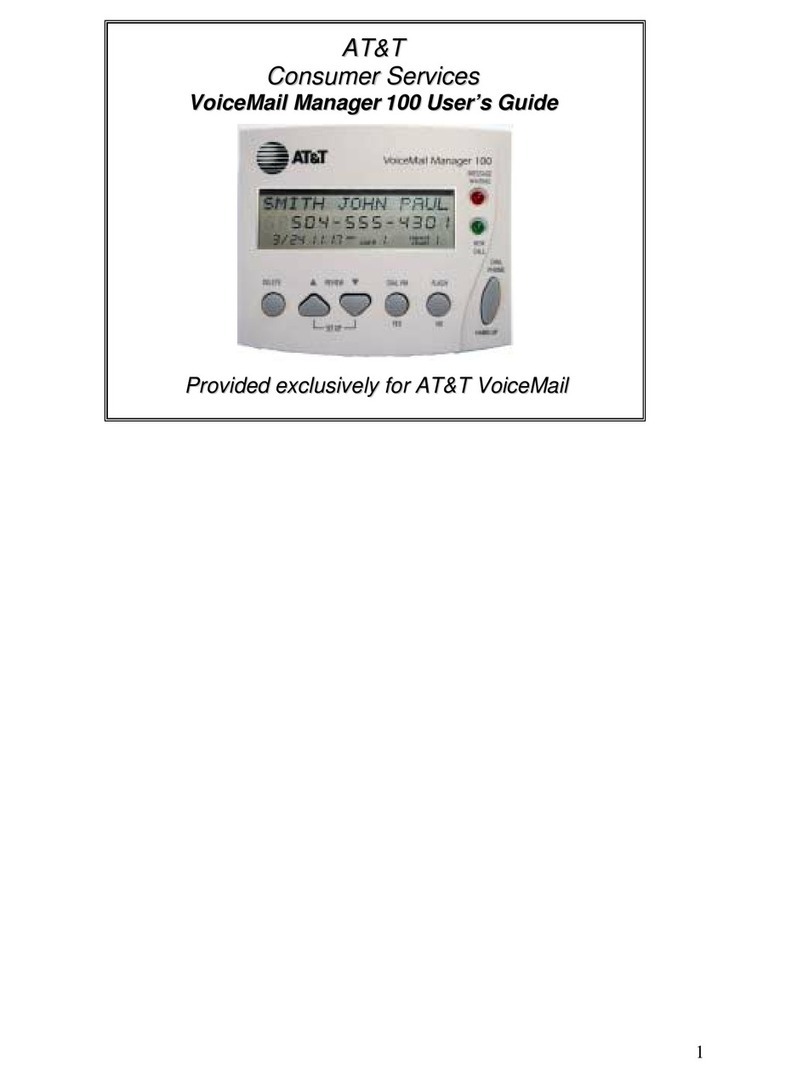
AT&T 100 User manual

AT&T
AT&T Merlin II Service manual

AT&T
AT&T Lucent Technologies MERLIN LEGEND Quick start guide

AT&T
AT&T Classic Mail Voice Messaging System User manual

AT&T
AT&T MERLIN MAIL User manual

AT&T
AT&T AUDIX Voice Power Product manual

AT&T
AT&T MERLIN MAIL User guide