LINK
POWER
LINK
POWER
LINK
POWER
LINK
POWER
LINK
POWER
LINK
POWER
LINK
POWER
LINK
POWER
LINK
POWER
LINK
POWER
LINK
POWER
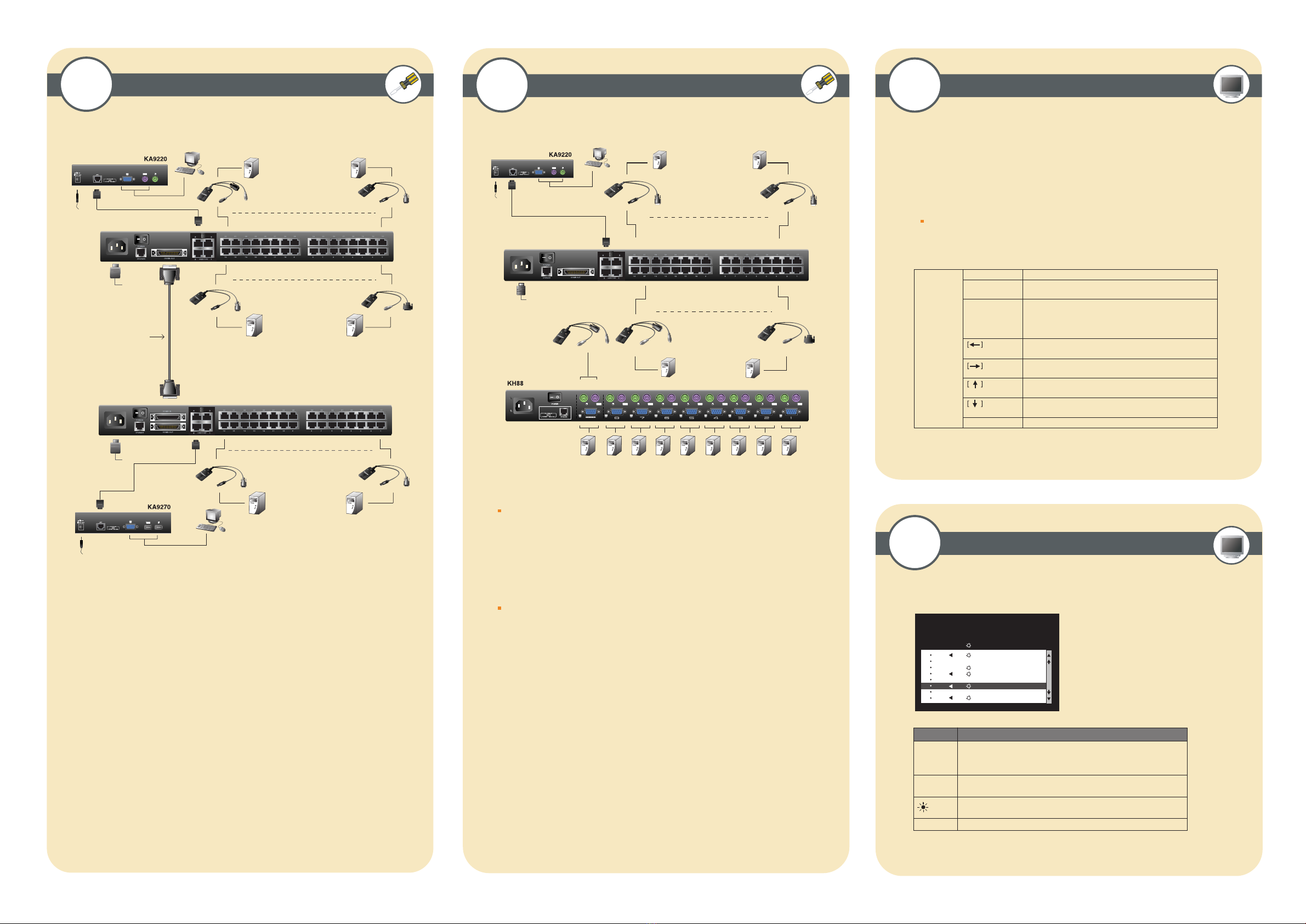
!
Daisy Chain Cable
KA9131
KA9120
PC SUN (USB)
KA9170 KA9130
KA9170 KA9130
SUNMac
SUNMac
1. Make sure that power to all the devices you will be connecting up has been turned off.
2. Use a daisy chain cable set to connect the Chain Out port of the parent Matrix K V M
Switch unit to the Chain I n port of the child Matrix K V M Switch unit.
3. If you wish to install any consoles on this switch, follow the procedure described for
the Single Stage Installation.
4. Use K V M Adapter cables to connect any available CPU Port on the Matrix K V M
Switch to the K eyboard, V ideo and Mouse ports of the computers you are installing
5. R epeat the above steps for any additional Matrix K V M Switch units you wish to add
to the chain.
7Daisy Chained Installation
F 1 : G O T O F 3 : S E T F 5 : S K P F 7 : S C A N X
F 2 : L I S T F 4 : A D M F 6 : B R C F 8 : L O U T zzz
S U P E R A D M I N I S T R A T O R S N : 0 2 / 0 8
L IS T : A L L
P N Q V N AM E
01 A T E N IN TL .C O . 1
02 A T E N IN TL .C O . 2
03 A T E N IN TL .C O . 3
06 FAX S E R V E R 1
05 FAX S E R V E R 2
06 3 WE B S E R V E R 1
07 4 WE B S E R V E R 2
08 5 MA IL S E R VE R 1
8 Cascaded Installation Invoking Hotkey Mode (HKM)
9
OSD Main Screen Headings
10
[Num L ock]
+ [-]
Switches access to the computer that corresponds to that Port I D.
Sets the A uto Scan interval to n seconds - where n is a number
from 1 - 255.Invokes A uto Scan Mode.
When A uto Scan Mode is in effect, [P] or L eft Click pauses
Auto Scanning.
When A uto Scanning is paused, pressing A ny K ey or another
L eft C lick resumes A uto Scanning.
Invokes Skip Mode and Skips from the current port to the first
accessible port previous to it.
Invokes Skip Mode and Skips from the current port to the next
accessible port.
Invokes Skip Mode and Skips from the current port to the last
accessible port of the previous Station.
Invokes Skip Mode and Skips from the current port to the first
accessible port of the next Station.
Toggles the B eeper On or Off.
[Port I D] [E nter]
[A]
[B ]
[T ] [ n] [ E nter]
QV
NAME
PN
This column lists the Port ID numbers (Station Number - Port Number)
for all the CPU ports on the installation. T he simplest method to access
a particular computer is move the Highlight B ar to it, then press E nter.
If a port has selected for Quick V iew scanning an arrowhead displays
in this column to indicate so.
The computers that are powered on and are On L ine have a Sun symbol
in this column to indicate so.
If a port has been given a name, its name appears in this column.
H eading E xplanation
KA9131
KA9120
KA9120
KA9170
KA9130
SUN
Mac SUN (USB)
PC
Up to 32 additional K V M switches can be cascaded from the K M0432's CPU ports.
NOTE : Matrix K V M Switch's cannot be cascaded. Y ou must use the Altusen K H88 or
K H0116 cascading
1. Make sure that power to all the devices you will be connecting up has been turned off.
2. Use Cat 5 cable to connect any available CPU Port on the First Stage unit (the K M0432) to
a PS/2 style K V M adapter cable; plug the adapter cable's K V M connectors to the K eyboard,
V ideo, and Mouse Console ports of the Second Stage unit.
NOTE : The distance between the Second Stage unit and the Matrix K V M Switch must not
exceed 150m (500')
3. Plug the Second Stage unit's power adapter into an AC source; plug the power adapter
cable into the unit's Power Socket.
4. Connect the K V M converter (K A 9120) with the console on the second level K V M.
Then use CA T 5 cable to connect the K V M converter to the CPU side of the Matrix K V M.
5. R epeat steps 3 Ð 4 for any other Second Stage units you wish to connect
6. T urn on the power for the First Stage unit.
1. Press and hold down the <Num L ock> key
2. Press and release the <minus> key
3. R elease the <Num L ock> key
NOTE : The minus key must be released within one half second, otherwise the hotkey
operation is canceled
* A ctivate OSD, pr ess [Scroll L ock] [Scr oll L ock] or [C tr l] [C tr l ] *


