ATI Technologies Flexdeburr RC-660 Series User manual

Engineered Products for Robotic Productivity
Pinnacle Park • 1031 Goodworth Drive •Apex, NC 27539 USA• Tel: +1.919.772.0115 • Fax: +1.919.772.8259 • www.ati‑ia.com
ATI Radially‑Compliant Robotic Deburring Tools
Flexdeburr™
(Models 9150‑RC‑660‑ER and 9150‑RC‑660‑ER‑E)
Manual
US Patent # 6,974,286 B2
Document #: 9610‑50‑1017

Manual, Flexdeburr, RC‑660 Series
Document #9610‑50‑1017‑10
Pinnacle Park • 1031 Goodworth Drive •Apex, NC 27539 USA• Tel: +1.919.772.0115 • Fax: +1.919.772.8259 • www.ati‑ia.com
2
Foreword
CAUTION: This manual describes the function, application, and safety considerations of this
product. This manual must be read and understood before any attempt is made to install or
operate this product. Failure to do so may result in personnel injury and/or damage to equipment.
Information contained in this document is the property of ATI IndustrialAutomation, Inc (ATI) and shall not be
reproduced in whole or in part without prior written approval of ATI. The information herein is subject to change without
notice. This manual is periodically revised to reect and incorporate changes made to the product.
The information contained herein is condential and reserved exclusively for the customers and authorized agents of ATI
Industrial Automation and may not be divulged to any third party without prior written consent from ATI. No warranty
including implied warranties is made with regard to accuracy of this document or tness of this device for a particular
application. ATI Industrial Automation shall not be liable for any errors contained in this document or for any incidental
or consequential damages caused thereby.ATI Industrial Automation also reserves the right to make changes to this
manual at any time without prior notice.
ATI assumes no responsibility for any errors or omissions in this document.
©Copyright 2019 by ATI Industrial Automation. All rights reserved.
How to reach us:
Sale, Service and Information about ATI products:
ATI Industrial Automation
1031 Goodworth Drive
Apex, NC 27539 USA
www.ati‑ia.com
Tel: 919.772.0115
Fax: 919.772.8259
Application Engineering
Tel: 919.772.0115
Fax: 919.772.8259
E‑mail: applicationsengineers@ati‑ia.com

Manual, Flexdeburr, RC‑660 Series
Document #9610‑50‑1017‑10
Pinnacle Park • 1031 Goodworth Drive •Apex, NC 27539 USA• Tel: +1.919.772.0115 • Fax: +1.919.772.8259 • www.ati‑ia.com
3
Table of Contents
Foreword.......................................................................................................................................... 2
Glossary........................................................................................................................................... 5
1. Safety......................................................................................................................................... 6
1.1 ExplanationofNotications.........................................................................................................6
1.2 General Safety Guidelines............................................................................................................6
1.3 Safety Precautions........................................................................................................................7
2. Product Overview..................................................................................................................... 8
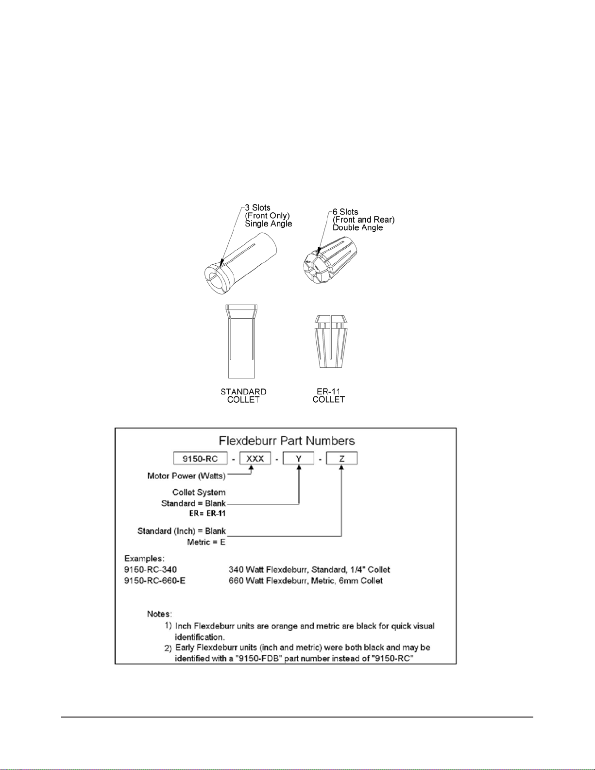
2.1 Tool Collet Systems ......................................................................................................................8
2.2 Deburring Tool Part Numbers ......................................................................................................9
2.3 Technical description..................................................................................................................10
2.3.1 Environmental Limitations................................................................................................10
2.3.1.1 Operation..........................................................................................................10
2.3.1.2 Storage.............................................................................................................10
2.3.2 Compliance Unit Performance .........................................................................................10
3. Installation .............................................................................................................................. 12
3.1 Transportation and Protection During Transportation............................................................12
3.2 Inspection of Condition When Delivered..................................................................................12
3.3 Unpacking and Handling............................................................................................................12
3.4 Storage and Preventive Maintenance during Storage.............................................................12
3.5 Side Mounting Installation..........................................................................................................13
3.6 Axial Mounting Installation.........................................................................................................14
3.7 Pneumatics..................................................................................................................................15
4. Operation ................................................................................................................................ 17
4.1 Safety Precautions......................................................................................................................17
4.2.1 Air Quality.........................................................................................................................18
4.2.2 No Lubrication..................................................................................................................18
4.2.3 Bur Selection, Design, and Maintenance.........................................................................18
4.2.4 Deburring Tool Approach Path Should be Slow and at an Angle .....................................18
4.2.5 No Axial Loading ..............................................................................................................18
4.2.6 Program the Robot to Incorporate 50% Compliance Travel of the Tool ...........................18
4.2 Normal Operation........................................................................................................................18
4.3 Flexdeburr Working Environment .............................................................................................19
4.4 Tool Center Point (TCP) Position and Programming...............................................................19
4.5 Cutter Operation and Bur Selection..........................................................................................21
4.5.1 Bur Selection....................................................................................................................21

Manual, Flexdeburr, RC‑660 Series
Document #9610‑50‑1017‑10
Pinnacle Park • 1031 Goodworth Drive •Apex, NC 27539 USA• Tel: +1.919.772.0115 • Fax: +1.919.772.8259 • www.ati‑ia.com
4
5. Maintenance............................................................................................................................ 24
5.1 Pneumatics..................................................................................................................................24
5.2 Lubrication...................................................................................................................................24
5.3 Spindle Boot Inspection.............................................................................................................24
5.4 Bur Inspection.............................................................................................................................24
5.5 Spindle Motion Inspection..........................................................................................................24
6. Troubleshooting and Service Procedures........................................................................... 25
6.1 Troubleshooting..........................................................................................................................25
6.2 Service Procedures.....................................................................................................................27
6.2.1 Bur and Collet Replacement ............................................................................................27
6.2.2 Turbine Motor Replacement.............................................................................................29
6.2.3 Ring Cylinder Assembly Replacement.............................................................................33
6.2.4 Rear Housing Assembly and Pivot Bearing Replacement ...............................................35
6.2.5 Spindle Boot Replacement...............................................................................................41
7. Serviceable Parts ................................................................................................................... 43
7.1 Accessories Tools, and Optional Replacement Parts .............................................................43
8. Specications ......................................................................................................................... 44
9. Drawings ................................................................................................................................. 45
10. Terms and Conditions of Sale............................................................................................... 48
10.1 Motor Life and Service Interval Statement................................................................................49
10.1.1 Turbine Motor Products (Flexdeburr (RC) models)..........................................................49

Manual, Flexdeburr, RC‑660 Series
Document #9610‑50‑1017‑10
Pinnacle Park • 1031 Goodworth Drive •Apex, NC 27539 USA• Tel: +1.919.772.0115 • Fax: +1.919.772.8259 • www.ati‑ia.com
5
Glossary
Term Denition
Adapter Plate Device for attaching the deburring tool to either a robot ange or a stationary
mounting surface.
Air Filter Device for removing contamination from air supply lines. Typically refers to
removal of particulates.
Burr Any unwanted, raised protrusion on the work piece.
Bur Cutting tool used to remove burs from the work piece. Alternatively referred to
as a rotary le, cutter, or bit.
Climb Milling Cutting method where the direction of cutter rotation and tool motion are the
same.
Coalescing Filter Device designed to remove liquid aerosols from the air supply lines.
Collet Gripping device used to hold cutting tools in the spindle.
Compliance The ability of the spindle to passively move in response to protrusions on or
deviations of the work piece.
Conventional Milling Method of cutting where the direction of tool motion is opposite that of tool
rotation.
End‑Effector Tool used by the robot to perform a particular function.
Regulator Device used to set and control the supplied air pressure to lower acceptable
level.
Solenoid Valve Electrically controlled device for switching air supplies on and off.
Spindle The rotating portion of the deburring tool assembly.
Turbine Air motor that drives the spindle.

Manual, Flexdeburr, RC‑660 Series
Document #9610‑50‑1017‑10
Pinnacle Park • 1031 Goodworth Drive •Apex, NC 27539 USA• Tel: +1.919.772.0115 • Fax: +1.919.772.8259 • www.ati‑ia.com
6
1. Safety
The safety section describes general safety guidelines to be followed with this product, explanations of the
notications found in this manual, and safety precautions that apply to the product. More specic notications are
imbedded within the sections of the manual (where they apply).
1.1 ExplanationofNotications
The following notications are specic to the product(s) covered by this manual. It is expected that the user
heed all notications from the robot manufacturer and/or the manufacturers of other components used in the
installation.
DANGER: Notication of information or instructions that if not followed will result in
death or serious injury. The notication provides information about the nature of the
hazardous situation, the consequences of not avoiding the hazard, and the method for
avoiding the situation.
WARNING: Notication of information or instructions that if not followed could result
in death or serious injury. The notication provides information about the nature of the
hazardous situation, the consequences of not avoiding the hazard, and the method for
avoiding the situation.
CAUTION: Notication of information or instructions that if not followed could result
in moderate injury or will cause damage to equipment. The notication provides
information about the nature of the hazardous situation, the consequences of not
avoiding the hazard, and the method for avoiding the situation.
NOTICE: Notication of specic information or instructions about maintaining, operating,
installing, or setting up the product that if not followed could result in damage to equipment. The
notication can emphasize, but is not limited to: specic grease types, best operating practices,
and maintenance tips.
1.2 General Safety Guidelines
Prior to purchase, installation, and operation of the Flexdeburr product, the customer should rst read and
understand the operating procedures and information described in this manual. Never use the deburring tool
for any purposes, or in any ways, not explicitly described in this manual. Follow installation instructions and
pneumatic connections as described in this manual.
All pneumatic ttings and tubing must be capable of withstanding the repetitive motions of the application
without failing. The routing of pneumatic lines must minimize the possibility of over stressing, pullout, or
kinking the lines. Failure to do so can cause some critical pneumatic lines not to function properly and may
result in damage to equipment.

Manual, Flexdeburr, RC‑660 Series
Document #9610‑50‑1017‑10
Pinnacle Park • 1031 Goodworth Drive •Apex, NC 27539 USA• Tel: +1.919.772.0115 • Fax: +1.919.772.8259 • www.ati‑ia.com
7
1.3 Safety Precautions
WARNING: Never operate the Flexdeburr product without wearing hearing protection.
High sound levels can occur during cutting. Failure to wear hearing protect can cause
hearing impairment. Always use hearing protection while working in the proximity of the
deburring tool.
WARNING: Never operate the Flexdeburr product without wearing eye protection.
Flying debris can cause injury. Always use eye protection while working in the proximity
of the deburring tool.
CAUTION: Do not use burs rated for less than the speed of the RC deburring tool
being used. Using these may cause injury or damage equipment. Always use burs
rated for at least the speed of the RC deburring tool being used.
CAUTION: Do not use spare parts other than original ATI spare parts. Use of spare
parts not supplied by ATI can damage equipment and void the warranty. Always use
original ATI spare parts.
CAUTION: Never be present near the deburring tool while it is started or in operation.
Flying debris and rotating parts can cause injury. If it is necessary to approach the
deburring tool while in motion, stand behind appropriate Plexiglas windows. Provide a
barrier to prohibit people from approaching the deburring tool while in operation must
secure the installation.
CAUTION: Do not perform maintenance or repair on the Flexdeburr product unless the
tool is safely supported or placed in the tool stand and air has been turned off. Injury
or equipment damage can occur with tool not placed and air on. Place the tool safely
in the tool stand and turn off the air before performing maintenance or repair on the
Flexdeburr product.
NOTICE: Turbine motors are not serviceable at this time. Refer to Section 10—Terms and
Conditions of Sale. To maximize the life of turbine motor products the customer should follow
closely the normal operating procedures outlined in the product manual. The air must be totally
lube free and ltered to remove particulates and moisture. Exposing the turbine motors to oil in
the air supply results in premature failure.

Manual, Flexdeburr, RC‑660 Series
Document #9610‑50‑1017‑10
Pinnacle Park • 1031 Goodworth Drive •Apex, NC 27539 USA• Tel: +1.919.772.0115 • Fax: +1.919.772.8259 • www.ati‑ia.com
8
2. Product Overview
The Radially‑Compliant (RC) deburring tool, also known as Flexdeburr, is a turbine‑driven deburring unit for
deburring aluminum, plastic, steel, etc. with a robot or CNC machine. The RC Deburring Tool is especially suited
for removal of parting lines and ash from parts. However, its exible design allows it to be used in a wide variety
of applications.
The RC deburring tool’s pneumatically controlled, articulated design allows the cutting bur to follow the part
prole and compensate for surface irregularities while maintaining a constant, settable force. This allows high feed
rates with uniform quality in any orientation. The tool also requires no oil, allowing clean exhaust air to be vented
directly into the work environment.
Compliance is supported by air pressure applied to the shaft of the unit. The RC deburring tool also utilizes
standard industrial tungsten‑carbide bits which allows for adaptation to changing assembly lines and
part requirements.
The RC‑660‑ER provides for (2) mounting types; a side mounting and an axial mounting. The side mounting
provides (2) locating dowel pins and (4) threaded holes. The axial mounting utilizes a tapered ange that requires
an adapter plate. Custom adapter plates for both side and axial mounting are available from ATI. Refer to
Section 9—Drawings for more information.
The RC‑660‑ER is equipped with a 1/2" Push‑to Connect tting to supply the motor air and a 5/32" [4 mm] Push‑to
Connect tting to supply the compliance air.
A tool collet system secures the bur. Many collet sizes are available to accommodate a wide variety of applications.
Figure 2.1—RC‑660‑ER Deburring Tool
Compliance Air
Connection
Motor Air Connection
Tool Collet
Side Mounting
Axial
Mounting
2.1 Tool Collet Systems
All Flexdeburr products utilize removable collets to grip customer‑supplied cutting tools. Different collet
diameters may be substituted to retain numerous cutter shank diameters. The collet retaining nut is loosened
to open the collet allowing cutting tools to be removed and inserted. Once the tool is set to the desired depth,
spanner wrenches are used to tighten the collet nut causing the collet to collapse and secure the cutting
tool. The turbine motor design does not allow the installation of spindle brakes or Quick Change (drawbar)
collet systems.

Manual, Flexdeburr, RC‑660 Series
Document #9610‑50‑1017‑10
Pinnacle Park • 1031 Goodworth Drive •Apex, NC 27539 USA• Tel: +1.919.772.0115 • Fax: +1.919.772.8259 • www.ati‑ia.com
9
The ATI RC‑660‑ER uses an ER‑11 collet system to hold cutting tools. The ER collet is a commercial,
double‑angle design offering greater tool gripping force, less tool runout and an extended grip range. The
collets are available from many sources in many different gripping diameters. ER‑11 collets can achieve
runout tolerances below 0.0005” [0.013 mm] and provide a gripping range up to 0.040” [1 mm]. This allows
a standard 1/4 inch ER‑11 collet to safely and accurately hold a metric 6 mm diameter cutter. However, the
ER‑11 collet system represents a greater initial expense and its wrenches and collet nut are more delicate.
The ER collet system is not interchangeable with the collet design utilized on other ATI deburring tools. An
ER‑11 collet cannot be used in a standard Flexdeburr and the standard Flexdeburr collet cannot be used with
a turbine motor designed for the ER‑11 collet system. Flexdeburr units with “ER” appearing in their Part
Number utilize only ER‑11 collets.
Figure 2.2—Tool Collets
2.2 Deburring Tool Part Numbers

Manual, Flexdeburr, RC‑660 Series
Document #9610‑50‑1017‑10
Pinnacle Park • 1031 Goodworth Drive •Apex, NC 27539 USA• Tel: +1.919.772.0115 • Fax: +1.919.772.8259 • www.ati‑ia.com
10
2.3 Technical description
The technical overview of the product is provided in the following tables and graphs. For additional
technical specications, refer to Section 8—Specications.
2.3.1 Environmental Limitations
2.3.1.1 Operation
Table 2.1—Operation
Installation
position
Mounted to robot using the side mounting pattern
or rear adapter ange. Refer to Section 3.5—Side
Mounting Installation and Section 3.6—Axial Mounting
Installation. The ange is specic to each type of robot.
This optional ange is normally supplied by ATI in a
blank form suitable for customer modication. Refer to
Section 9—Drawings.
Mounted to a table or stand by means of the bench
adapter (the robot is carrying the work piece).
Temperature
range 5°C–35°C
(41°F–95°F)
Utilities
The tool requires the following:
• Clean, dry, ltered, non‑lubricated air.
• A coalescing lter and lter elements rated
5 micron or better.
• The motor spindle must be supplied air at
6.2 bar (90 psi).
• The radial compliance (centering) air must be
supplied from a regulated source between
1.0–4.1 bar (15–60 psi).
2.3.1.2 Storage
Table 2.2—Storage
Temperature
range 0°C–45°C
(32°F–113°F)
Conditions
The tool should be stored in its crate and in a dry
place.
When not in use, keep the unit in its crate if possible.
Consult Section 3.4—Storage and Preventive
Maintenance during Storage of this manual.
2.3.2 Compliance Unit Performance
The graphs in Figure 2.3 illustrate the variation of compliance force with applied air pressure in the
vertical orientation with the collet pointed toward the ground. Measurements may vary from one
product to another and should only be treated as nominal.
The actual force characteristics are dependent on mounting orientation and condition of the unit. In
applications, where the deburring tool is mounted horizontally, additional compliance air pressure
is required to overcome the weight of the motor. Compliance pressure is also dependent upon the
material of the work piece, type of bur tool, and the amount of material that is removed.
The turbine motor attempts to maintain its full rated speed even under loaded conditions. However,
when extremely heavy cuts are taken, the motor may eventually stall. Therefore, multiple, light
passes are preferred over slow, heavy cuts.

Manual, Flexdeburr, RC‑660 Series
Document #9610‑50‑1017‑10
Pinnacle Park • 1031 Goodworth Drive •Apex, NC 27539 USA• Tel: +1.919.772.0115 • Fax: +1.919.772.8259 • www.ati‑ia.com
11
Figure 2.3—RC‑660‑ER Series Radial Compliance Force Curves (Measured at the Spindle Tip)
RC-660 Series Radial Contact Force
0
5
10
15
20
25
30
35
40
45
50
1.0 2.0 3.0 4.0
Centering Air Pressure (Bar)
Radial Force (N)
RC-660 Series Radial Contact Force
0
1
2
3
4
5
6
7
8
9
10
11
10 20 30 40 50 60 70
Centering Air Pressure (PSI)
Radial Force (lbf)

Manual, Flexdeburr, RC‑660 Series
Document #9610‑50‑1017‑10
Pinnacle Park • 1031 Goodworth Drive •Apex, NC 27539 USA• Tel: +1.919.772.0115 • Fax: +1.919.772.8259 • www.ati‑ia.com
12
3. Installation
The RC‑660‑ER Deburring Tool is delivered fully assembled. Optional equipment such as: mounting adapter plates,
burs, and additional collets are separate.
3.1 Transportation and Protection During Transportation
The RC deburring tool is packaged in a crate designed to secure and protect it during transportation. Always
use the crate when transporting the deburring tool in order to minimize the risk of damage.
3.2 Inspection of Condition When Delivered
Upon receipt, the following should be checked:
• Delivery in accordance with freight documents.
• Packaging in good condition.
If there is damage to any of the packaging, or if any of the goods have been exposed to abnormal handling,
unpack those parts that may have been damaged for a closer inspection. If necessary, notify ATI for
assistance in evaluation of the product condition.
3.3 Unpacking and Handling
The deburring tool should always be placed inside the accompanying box (crate) during transportation,
storing, and handling.
Pneumatic lines and electrical cables are attached, bundled, and must be strain‑relieved in a manner that
allows for freedom of movement during operation.
3.4 Storage and Preventive Maintenance during Storage
The deburring tool should be stored in its crate when it is not in use. The deburring tool should also be
stored in a dry place.
For long‑term storage, the deburring tool should be thoroughly cleaned of any burrs or debris. It should not
be disassembled. Place the deburring tool inside a sealed, plastic bag inside the crate.

Manual, Flexdeburr, RC‑660 Series
Document #9610‑50‑1017‑10
Pinnacle Park • 1031 Goodworth Drive •Apex, NC 27539 USA• Tel: +1.919.772.0115 • Fax: +1.919.772.8259 • www.ati‑ia.com
13
3.5 Side Mounting Installation
The side mounting pattern of the RC deburring tool consists of (2) dowel pin holes and a number of threaded
holes as shown in the following gure. The maximum fastener length specied must not be exceeded, or the
fasteners interfere with the compliant motion of the turbine motor spindle. Refer to Section 9—Drawings for
more information.
CAUTION: Lock washers are recommended on all mounting fasteners. Do not use
liquid thread lockers on the mounting fasteners as this may damage or remove thread
inserts during disassembly.
Figure 3.1—Bench (Side) Installation (The Model Is Shown for Reference).
Side Mounting
on Front Housing
Assembly
(4) M5 Socket Head
Cap Screws
Lock Washer
Benchtop Interface
Plate Assembly

Manual, Flexdeburr, RC‑660 Series
Document #9610‑50‑1017‑10
Pinnacle Park • 1031 Goodworth Drive •Apex, NC 27539 USA• Tel: +1.919.772.0115 • Fax: +1.919.772.8259 • www.ati‑ia.com
14
3.6 Axial Mounting Installation
A blank robot adapter plate is also available to allow axial mounting off the rear of the deburring tool
housing. This plate may be modied by the system integrator or by the owner/user of the Flexdeburr. ATI
can provide custom interface plates and adapters upon request. An optional bench mount adapter plate
allows the deburring tool to be permanently attached to a bench or other work surface (refer to the following
gure). If the RC deburring tool is permanently mounted to a work surface, the robot carries the part to be
deburred to the deburring tool. Refer to Section 9—Drawings for more information.
Figure 3.2—Axial Installation
(2) M5 Socket Head Cap Screws
Blank Interface Plate
Axial Mounting Flange on rear Housing Assembly
Clamping Collar
Clamping Collar

Manual, Flexdeburr, RC‑660 Series
Document #9610‑50‑1017‑10
Pinnacle Park • 1031 Goodworth Drive •Apex, NC 27539 USA• Tel: +1.919.772.0115 • Fax: +1.919.772.8259 • www.ati‑ia.com
15
3.7 Pneumatics
Connect the RC deburring tool as shown in Figure 3.3.
Figure 3.3—Pneumatic Connections
FILTER
HIGH-FLOW REGULATOR
6.2 BAR [90 PSI]
PRECISION REGULATOR
0-4.2 BAR [0-60 PSI]
SPINDLE AIR
SOLENOID VALVE
(2-WAY)
SPINDLE
MOTOR
COMPLIANCE
(CENTERING)
CYLINDERS
VENT TO
ATMOSPHERE
SUPPLY AIR:
CLEAN, DRY,
NON-LUBRICATED
6.9 BAR MIN.
[100 PSI]
WARNING: All pneumatic ttings and tubing must be capable of withstanding the
repetitive motions of the application without failing. The routing of pneumatic lines must
minimize the possibility of over stressing, pullout, or kinking the lines. Failure to do
so can cause some critical pneumatic lines not to function properly and may result in
damage to equipment.
The air supply should be dry, ltered, and free of oil. A coalescing lter with elements rated for 5 micron or
better is required.
A high‑ow air pressure regulator is required to supply the spindle motor at 6.2 bar (90 psi). A second,
precision, self‑relieving regulator supplies air for the compliance or centering force.
The compliance force is applied radially and is adjusted until the desired cut is made. The robot’s traversing
speed will also be adjusted to achieve the desired nish.
CAUTION: Pneumatic components used for the motor drive circuit must be capable
of meeting the air consumption requirements (See Section8—Specications ). Poor
performance will result if the correct components are not used.
Conventional, customer‑supplied, pneumatic components are used to control the air supply to the
deburring tool. ATI recommends that the user install a high‑ow pneumatic pressure regulator (ATI Part
#9150‑FFR‑90, or equivalent. See Section8—Specications for the maximum ow requirements) and
a high‑ow valve to properly supply a stable air supply of 6.2 bar (90 psi) to the spindle motor. The RC
deburring tool will not operate properly if supplied air below 6.2 bar (90 psi).
A second, precision, self‑relieving regulator (ATI Part # 9150‑PPR‑60, or equivalent) is used to supply
the compliance (centering) mechanism. This pressure corresponds to the side force on the rotary bur. Very
little airow is required for the compliance mechanism. As a result, a signicantly smaller valve to be used
(Consult the valve and regulator supplier’s literature when selecting these components).

Manual, Flexdeburr, RC‑660 Series
Document #9610‑50‑1017‑10
Pinnacle Park • 1031 Goodworth Drive •Apex, NC 27539 USA• Tel: +1.919.772.0115 • Fax: +1.919.772.8259 • www.ati‑ia.com
16
If the complete work piece can be deburred with equal force, a conventional, manual pressure regulator
can be used for compliance. If the burrs to be removed vary from place to place on the work piece, and this
variation is repeatable for all work pieces of the same type, it may be necessary to adjust the force using an
analog pressure regulator controlled from the robot. An analog output port in the robot or logic controller
will be needed.
Solenoid valves are actuated from the robot or program logic controller by means of a digital output signal.
Table 3.1—Pneumatic Connections
Function Connection Type Pressure
Motor Inlet
9150‑RC‑660‑ER 1/2" Quick Connect Tube 6.2 bar
(90 psi)9150‑RC‑660‑ER‑E
Compliance (Radial) Force Inlet
9150‑RC‑660‑ER and
9150‑RC‑660‑ER‑E
5/32” (4 mm) Quick Connect Tube
Alternate: Remove Supplied Fitting to use 1/8‑NPT Port
1.0–4.1 bar
(15–60 psi)
(Maximum)
Exhaust Vented to Atmosphere through the Housing Not Applicable
It is recommended that exible plastic tubing be used for the motor air supply and the compliance force
air supply. The installed ttings can be removed to expose tapped supply ports thus allowing the use
of alternate, customer‑supplied components. The turbine motor is extremely quiet and vents dry air to
the environment through the screen‑covered ports on the side of the housing. No mufers are required.
Information on the sound intensity is provided in Section8—Specications. To reduce the sound from the
cutting operation in neighboring working areas, a customer‑supplied barrier surrounding the installation may
be installed (Plexiglas® or Lexan®is preferred, see Section 8—Specications).
The compliance force air supply pressure regulator should have a 0‑4.1 bar [0–60 psi] range. When
testing for the proper contact force, start with a very low pressure and increase slowly until the desired
cut is achieved.

Manual, Flexdeburr, RC‑660 Series
Document #9610‑50‑1017‑10
Pinnacle Park • 1031 Goodworth Drive •Apex, NC 27539 USA• Tel: +1.919.772.0115 • Fax: +1.919.772.8259 • www.ati‑ia.com
17
4. Operation
These operating instructions are intended to help system integrators program, start up, and complete a robotic
deburring cell containing a deburring tool. The system integrator should be familiar with the task of deburring, in
general, and should have extensive knowledge relating to robots and automation incorporating robots.
4.1 Safety Precautions
DANGER: Never use the Flexdeburr for purposes other than robotic deburring. If used
in any other way, serious injury or damage to equipment may occur.
WARNING: All personnel, who are involved in operation of the RC deburring tool,
should have a thorough understanding of the operating procedures. Failure to follow
these procedures or neglecting safety precautions can create hazardous situations that
may injure personnel or damage the deburring installation and the RC deburring tool.
WARNING: Never operate the Flexdeburrproduct without wearing hearing protection.
High sound levels can occur during cutting. Failure to wear hearing protection can
cause hearing impairment. Always use hearing protection while working in proximity of
the deburring tool.
WARNING: Never operate the Flexdeburr product without wearing eye protection.
Flying debris can cause injury. Always use eye protection while working in the proximity
of the deburring tool.
CAUTION: Do not use burs rated for less than the speed of the RC deburring tool
being used. Using lower rated burs may cause injury or damage equipment. Always
use burs rated for at least the speed of the RC deburring tool being used.
CAUTION: Do not use spare parts other than original ATI spare parts. Use of spare
parts not supplied by ATI can damage equipment and void the warranty. Always use
original ATI spare parts.
CAUTION: Never be present near the deburring tool while it is started or in operation.
Flying debris and rotating parts can cause injury. If it is necessary to approach the
deburring tool while in motion, stand behind appropriate Plexiglas windows. Provide a
barrier to prohibit people from approaching the deburring tool while in operation.
CAUTION: Never use or start the deburring tool without rst reading and understanding
the operating procedures described in this manual. Never use the deburring tool for any
purposes, or in any ways, not explicitly described in this document. Using the deburring
tool without fully understanding the installation and operating procedures may cause
injury to personnel or damage to equipment. Mount the deburring tool and connect the
pneumatic control equipment as described in this manual. Operate the deburring tool
as described in the manual.

Manual, Flexdeburr, RC‑660 Series
Document #9610‑50‑1017‑10
Pinnacle Park • 1031 Goodworth Drive •Apex, NC 27539 USA• Tel: +1.919.772.0115 • Fax: +1.919.772.8259 • www.ati‑ia.com
18
4.2 Normal Operation
The following sections describes the normal operating conditions for RC deburring tools.
4.2.1 Air Quality
The air supply should be dry, ltered, and free of oil. A coalescing lter with elements rated for 5
micron or better is required. The air must be supplied at 6.2 bar (90 psi).
Air quality affects tool performance more than almost any other factor. Particulate can block airow
or impede vane motion. If deburring tools do receive proper air pressure, the tool stalls. Any water in
the system damages the housing and blades.
4.2.2 No Lubrication
No lubrication is required.
Turbine motors cannot have any oil in the motor air supply. Oil damages the speed regulator and
causes the motor speed to uctuate out of tolerance.
4.2.3 Bur Selection, Design, and Maintenance
Use a carbide media.
RC tools have higher operating speeds and the media must be rated to RC idle speed at a minimum.
Check media quality regularly to ensure it is not dull or worn. Using worn media causes a poor
surface nish and increased wear on the bearings that results in premature tool failure.
Do not use shank extensions because the large moment loads combined with the high speed
can be dangerous.
Brushes are not recommended because the maximum rated speed of the brush is less than the ideal
speed of the deburring tool.
Do not use a tool that requires axial loading.
4.2.4 Deburring Tool Approach Path Should be Slow and at an Angle
The deburring tool should approach the workpiece slowly and at an angle.
When beginning a deburring pass, try to minimize the initial impact on the work piece by slowly
approaching the tool at an angle while maintaining a slightly parallel path with the surface.
If the tool quickly approaches perpendicularly to the workpiece, the result is gouging and
premature wear of the tool bearings and cutting bit. Additionally, collisions could result and create
a hazardous situation for both personnel and equipment.
4.2.5 No Axial Loading
Do not apply axial loads that are parallel to the axis of the tool’s rotation.
Do not deburr shallow edges where the cutter contacts the parent material below the edge; otherwise,
axial loading is applied on the tool and bearings and results in premature failing of the unit.
When deburring holes, interpolate the perimeter. Do not use a countersink tool; otherwise, axial
loading occurs and causes premature wear on the bearings.
4.2.6 Program the Robot to Incorporate 50% Compliance Travel of the Tool
Program the robot to have the tool’s compliance at 50% travel when on the nominal path.
As the part’s edge deviates from the perfect path, the cutting bit can use compliance to follow along
high and low spots without losing contact or hitting the positive stop and gouging.
Do not “bottom out” the compliance and hit the positive stop.
Repeated impacts on the positive stop create slop in the compliance and reduce
recentering repeatability.

Manual, Flexdeburr, RC‑660 Series
Document #9610‑50‑1017‑10
Pinnacle Park • 1031 Goodworth Drive •Apex, NC 27539 USA• Tel: +1.919.772.0115 • Fax: +1.919.772.8259 • www.ati‑ia.com
19
4.3 Flexdeburr Working Environment
As described in previous sections, the RC deburring tool should only be used in conjunction with a robot in
a secured work cell/chamber.
The work cell must be secured by means of barriers to prohibit personnel from entering the cell. A lockable
door should be included as a part of the barrier in order to facilitate access to the cell for authorized
personnel only. The barrier could consist partly or fully of Plexiglas to facilitate observation of the
deburring operations.
During system or deburring tool maintenance, make sure the RC deburring tool and robot are stopped
before entering the robot cell. When installing and testing, Never be present in the cell when the Deburring
tool is running.
Be aware of rotating parts. Use eye‑protection while working around the deburring tool.
Be aware of high sound levels. While the Flexdeburr air motor is not loud, the cutting action associated
with deburring frequently is loud. Always use hearing protection while working in the neighborhood of the
deburring cell.
The deburring tool should not be used to deburr materials that are prone to fracture. A fracturing work
piece may result in pieces of material damaging surrounding working environment and personnel. Material
removed correctly should be in the form of chips.
4.4 Tool Center Point (TCP) Position and Programming
Figure 4.1 shows the RC deburring tool dimensions. The Flexdeburr provides radial compliance and
performs best when the cuts taken are not excessively deep. The deburring tool spindle must Never be
running while programming the robot. During teaching, the compliance air must be on and supplied above a
minimum of 0.35 bar (5 psi).
Two programming methods are suggested but others are possible. In the rst method, a dowel pin of suitable
diameter is inserted in place of a cutting tool (simulating the cutter shank diameter) when teaching the robot
path. For example, 6 mm collets require a 6 mm diameter pin of suitable length. The dowel pin should
extend sufciently from the collet to reach the surface on the bur where cutting is desired (see Figure 4.1).
The diameter of the cutter should not exceed that of the dowel pin by more than the compliance of the RC
deburring tool.

Manual, Flexdeburr, RC‑660 Series
Document #9610‑50‑1017‑10
Pinnacle Park • 1031 Goodworth Drive •Apex, NC 27539 USA• Tel: +1.919.772.0115 • Fax: +1.919.772.8259 • www.ati‑ia.com
20
Another programming method is to teach the path using the centerline of the bur as a guide, following the
edge of the part, and then manually or automatically adding offsets to the robot path points to achieve the
nal correct bur path (see Figure 4.2). The programming method used depends on the robot’s capabilities
and programmer preferences.
Figure 4.1—Flexdeburr Dowel Teaching Tool
Figure 4.2—Flexdeburr Pointed Teaching Tool
This manual suits for next models
2
Table of contents
Other ATI Technologies Industrial Equipment manuals

ATI Technologies
ATI Technologies 39-0214 User manual

ATI Technologies
ATI Technologies RCV User manual

ATI Technologies
ATI Technologies Speedeburr 9150-AC-90 User manual

ATI Technologies
ATI Technologies QC-113 User manual

ATI Technologies
ATI Technologies QC-313 User manual

ATI Technologies
ATI Technologies QC-300 User manual

ATI Technologies
ATI Technologies QC-201 User manual

ATI Technologies
ATI Technologies Axia Series User manual

ATI Technologies
ATI Technologies QC-210 User manual

ATI Technologies
ATI Technologies REMOTE WONDER II User manual