ATI Technologies QC-313 User manual

Manual, Tool Changer, QC‑313
Document #9620‑20‑B‑313 Series Base Tool Changer‑06
Pinnacle Park • 1031 Goodworth Drive •Apex, NC 27539 • Tel: 919.772.0115 • Fax: 919.772.8259 • www.ati‑ia.com • Email: info@ati‑ia.com
B-1
Table of Contents
B. Robotic Tool Changer .............................................................................................................B-3
QC-313 Series—Robotic Tool Changer......................................................................................B-3
1. Product Overview..................................................................................................................B-3
1.1 Master Plate Assembly ............................................................................................................. B-4
1.2 Tool Plate Assembly.................................................................................................................. B-5
1.3 Optional Modules...................................................................................................................... B-5
2. Installation .............................................................................................................................B-6
2.1 Master Interface......................................................................................................................... B-7
2.2 Master Plate Installation........................................................................................................... B-8
2.3 Master Plate Removal............................................................................................................... B-8
2.4 Tool Interface............................................................................................................................. B-9
2.5 Tool Plate Installation ............................................................................................................. B-10
2.6 Tool Plate Removal ................................................................................................................. B-10
2.7 Pneumatic Connections ..........................................................................................................B-11
2.7.1 Valve Requirements for Air Adapter Modules................................................................B-11
2.8 Electrical Connections............................................................................................................ B-12
2.8.1 PNP Type Lock, Unlock and RTL Sensors (-SM sensor designations).........................B-12
3. Operation .............................................................................................................................B-13
3.1 Conditions for Coupling......................................................................................................... B-14
3.2 Fail-Safe Operation ................................................................................................................. B-15
3.3 Conditions for Uncoupling..................................................................................................... B-16
3.4 ToolIdentication.................................................................................................................... B-16
3.5 Tool Storage Considerations ................................................................................................. B-17
4. Maintenance.........................................................................................................................B-18
4.1 Preventive Maintenance ......................................................................................................... B-18
4.2 Cleaning and Lubrication of the Locking Mechanism and Alignment Pins....................... B-19
4.3 Pin Block Inspection and Cleaning ....................................................................................... B-21
5. Troubleshooting and Service Procedures........................................................................B-22
5.1 Troubleshooting Procedures ................................................................................................. B-22
5.2 Service Procedures................................................................................................................. B-23
5.2.1 Lock and Unlock Sensor Replacement Procedures......................................................B-23
5.2.2 RTL Sensor Replacement Procedure............................................................................B-25
5.2.3 R1 Sensor Cable Replacement.....................................................................................B-26
5.2.4 R2 Sensor Cable Replacement.....................................................................................B-28
5.2.5 V-ring Seal Inspection and Replacement......................................................................B-30

Manual, Tool Changer, QC‑313
Document #9620‑20‑B‑313 Series Base Tool Changer‑06
Pinnacle Park • 1031 Goodworth Drive •Apex, NC 27539 • Tel: 919.772.0115 • Fax: 919.772.8259 • www.ati‑ia.com • Email: info@ati‑ia.com
B-2
5.2.6 Alignment Pin Replacement..........................................................................................B-31
6. Serviceable Parts ................................................................................................................B-33
6.1 Master Serviceable Parts........................................................................................................ B-33
6.2 Tool Serviceable Parts............................................................................................................ B-34
7. Specications ......................................................................................................................B-35
8. Drawings ..............................................................................................................................B-36
8.1 QC-313 Tool Changer.............................................................................................................. B-36

Manual, Tool Changer, QC‑313
Document #9620‑20‑B‑313 Series Base Tool Changer‑06
Pinnacle Park • 1031 Goodworth Drive •Apex, NC 27539 • Tel: 919.772.0115 • Fax: 919.772.8259 • www.ati‑ia.com • Email: info@ati‑ia.com
B-3
B. Robotic Tool Changer
QC-313 Series—Robotic Tool Changer
1. Product Overview
ATI Tool Changers enhance the versatility of a robot by enabling the use of multiple customer tools, such as:
grippers, vacuum cup tooling, pneumatic and electric motors, weld guns, and more.
The Tool Changer consists of a Master plate, which is attached to the robot arm, and a Tool plate, which is attached
to customer tooling. When the robot picks up the customer tooling, a pneumatically‑driven locking mechanism
couples the two plates. The patented, fail‑safe locking mechanism utilizes a multi‑tapered cam with ball locking
technology to ensure the Tool Changer does not uncouple if air pressure falls below 60 psi (4.1 bar) during
operation.
The robot can be programmed to select the desired customer tooling by coupling the Master plate to the Tool plate.
Electricity, uid, and other forces of energy transfer to the customer tooling through optional modules that are
attached to the Master and Tool plates. Refer to the ATI website for compatible modules or contact anATI sales
representative for more details.
For the most current product information and specications on the QC‑313 Series of Tool Changers, please click
the following link: QC‑313 Series

Manual, Tool Changer, QC‑313
Document #9620‑20‑B‑313 Series Base Tool Changer‑06
Pinnacle Park • 1031 Goodworth Drive •Apex, NC 27539 • Tel: 919.772.0115 • Fax: 919.772.8259 • www.ati‑ia.com • Email: info@ati‑ia.com
B-4
1.1 Master Plate Assembly
The Master plate assembly includes an anodized aluminum body, a hardened stainless steel locking
mechanism, and hardened steel alignment pins (see Figure 1.1).
The body or Master plate has (6) at sides for mounting of optional modules. In general, at ‘A’ is reserved
for an air/valve adapter module and a control/signal module. Flats “B1”, “B2”, “C”, “D1”, and “D2”
are fully interchangeable and optional modules can be arranged to suit the application or robot dress, as
required.
The locking mechanism consists of a cam, a male coupling, and chrome steel ball bearings.
Tapered pins located on the Master plate mate with bushings in the Tool plate to ensure repeatable alignment
during the coupling process. An extreme pressure grease is applied to the cam, male coupling, ball bearings,
and pins to enhance performance and maximize the life of the Master plate assembly.
Proximity sensors are designed into the body of the Master plate to verify the lock/unlock position of the
piston and cam. The sensors provide the lock and unlock (L/U) signals through the control/signal module.
Proximity sensor assemblies are mounted to the body of the Master plate to verify Tool plate presence when
coupled. The sensors provide a ready‑to‑lock (RTL) signal through the control/signal module.
A mounting pattern is machined into the Master plate for mounting to a robot arm or a interface plate. Refer
to Section 8—Drawings for details.
Figure 1.1—Master Plate Assembly
Proximity Sensor Assembly
Location (RTL Signal)
(9) Ball Bearing
Cam
Male Coupling
(2) Alignment Pin
Proximity Sensor Assembly
Location (RTL Signal)
Lock/Unlock Air supplied
through Air/Valve Adapter
mounted to Flat A
Cable Retaining Tabs
Common Ledge
Feature for Module
mounting
Internal Proximity Sensors
(Lock/Unlock) [Not Visible]

Manual, Tool Changer, QC‑313
Document #9620‑20‑B‑313 Series Base Tool Changer‑06
Pinnacle Park • 1031 Goodworth Drive •Apex, NC 27539 • Tel: 919.772.0115 • Fax: 919.772.8259 • www.ati‑ia.com • Email: info@ati‑ia.com
B-5
1.2 Tool Plate Assembly
The Tool plate assembly includes an anodized aluminum body, alignment bushings, and a hardened stainless
steel bearing race. The Tool plate has (6) at sides for mounting of optional modules.
Proximity sensor targets are mounted to the body of the Tool plate to verify Tool plate presence when
coupled. The targets are used by the proximity sensors in the Master plate to provide a ready‑to‑lock (RTL)
signal.
A mounting pattern is machined into the Tool plate for mounting to customer tooling or a tooling interface
plate. Refer to Section 8—Drawings for details.
Figure 1.2—Tool Plate Assembly
(2) Alignment Pin Bushing
Bearing Race
Proximity Sensor Assembly
Target (RTL)
Proximity Sensor Assembly Target (RTL)
Common Ledge Feature for
Module mounting
1.3 Optional Modules
There are (6) ats available for mounting of the optional modules for support of various utility pass through,
such as signal, uid/air, and electric.
For assistance in choosing the right modules for your particular application, visit the QC‑313 webpage
(QC‑313 Series) and click on compatible modules tab to see what is available or contact an ATI Sales
Representative directly.
In general, at ‘A’ is reserved for an air/valve adapter module and a control/signal module. Flats “B1”, “B2”,
“C”, “D1”, and “D2” are fully interchangeable and optional modules can be arranged to suit the application
or robot dress, as required.
The optional modules are mounted to the Master and Tool plate using a common ledge mounting feature.
Only (2) M6 socket head cap screws need to be unscrewed in order to remove the module from the Master/
Tool plate.

Manual, Tool Changer, QC‑313
Document #9620‑20‑B‑313 Series Base Tool Changer‑06
Pinnacle Park • 1031 Goodworth Drive •Apex, NC 27539 • Tel: 919.772.0115 • Fax: 919.772.8259 • www.ati‑ia.com • Email: info@ati‑ia.com
B-6
2. Installation
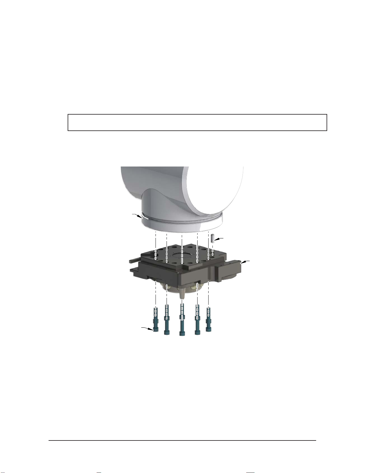
Mounting the Tool Changer requires the following, refer to Table 2.1.
WARNING: Do not perform maintenance or repair(s) on the Tool Changer or modules unless
the Tool is safely supported or placed in the tool stand, all energized circuits (e.g. electrical,
air, water, etc.) are turned off, pressurized connections are purged and power is discharged
from circuits in accordance with the customer specic safety practices and policies. Injury
or equipment damage can occur with the Tool not placed and energized circuits on. Place
the Tool in the tool stand, turn off and discharge all energized circuits, purge all pressurized
connections, and verify all circuits are de-energized before performing maintenance or
repair(s) on the Tool Changer or modules.
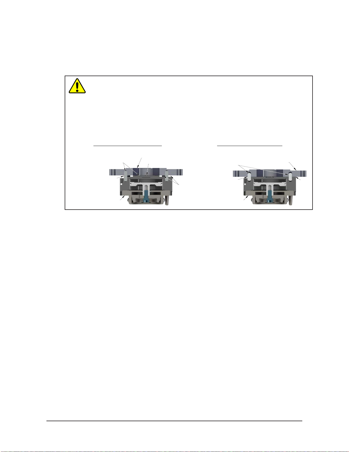
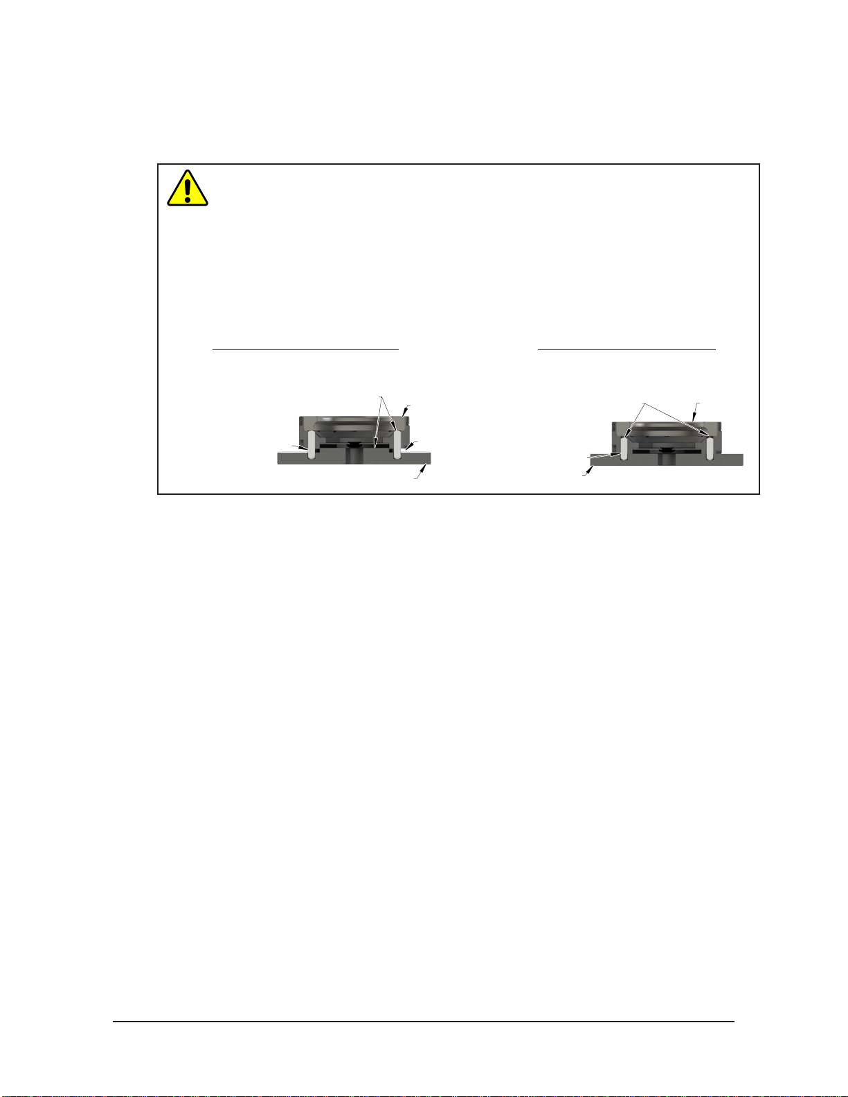
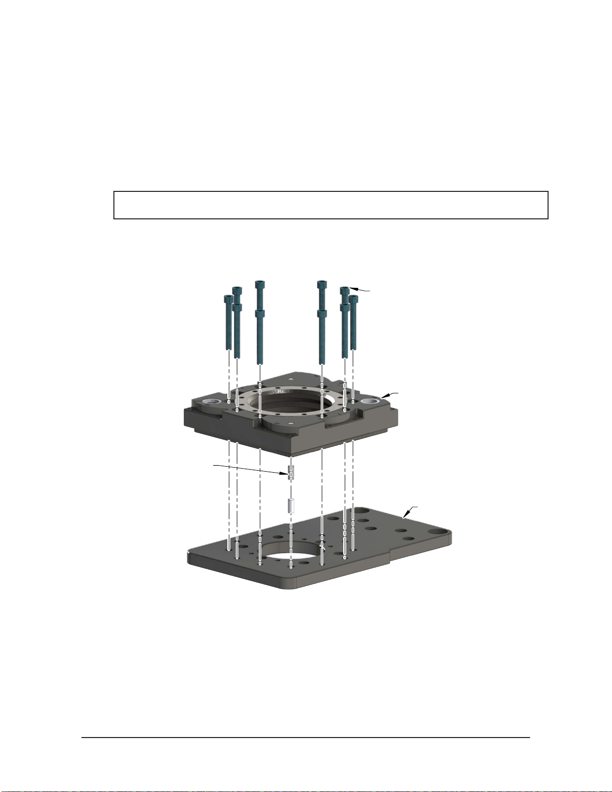
WARNING: Do not use lock washers under the head of the mounting fasteners or allow the
mounting fasteners to protrude above the mating surfaces of the Master and Tool plates.
Allowing fasteners to protrude above the mating surface will create a gap between the Master
and Tool plates and not allow the locking mechanism to fully engage, this can cause damage
to equipment or personal injury. The mounting fasteners must be ush or below the mating
surfaces of the Master and Tool plates.
Head of Mounting Fastener Must Be Flush or
Below Mating Surface. (Do Not Use Lock
Washer under Head of Mounting Fastener.)
Mating Surface
CAUTION: Thread locker applied to fasteners must not be used more than once. Fasteners
might become loose and cause equipment damage. Always apply new thread locker when
reusing fasteners.
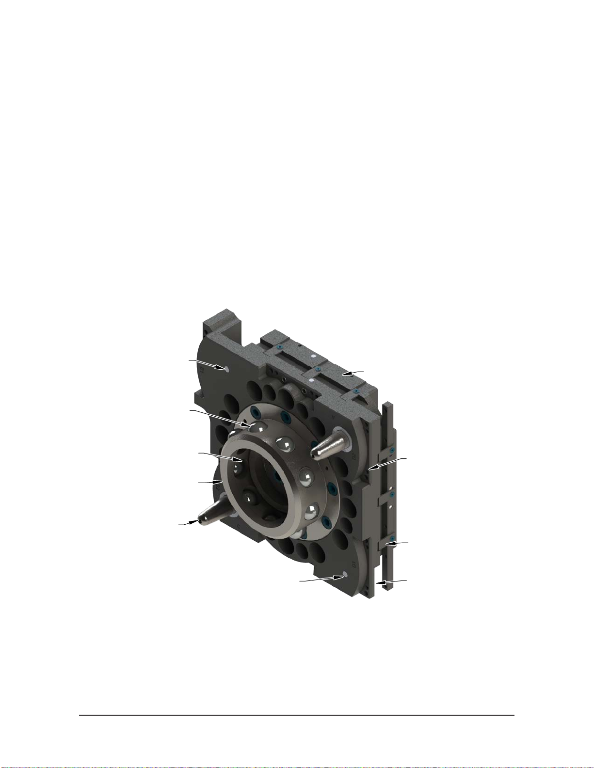
CAUTION: Do not use fasteners that exceed the thread depth in the Tool Changer. Refer to
Section 8—Drawings for details on mounting hole thread depth. Secure the Tool Changer with
the proper length fasteners. This is true for both robot and tool interfaces.
Table 2.1—FastenerSize,Class,andTorqueSpecications
Mounting Conditions Fastener Size
and Property
Class
Recommended
Torque
Master plate to Interface plate (6061-T6 aluminum)
Minimum thread engagement of 0.94” (24 mm) [1.5X fastener Ø]. M16-2.0
Class 12.9 165 ft-lbs
(225 Nm)
Master plate to Interface plate (6061-T6 aluminum)
Minimum thread engagement of 0.71” (18 mm) [1.5X fastener Ø]. M12-1.75
Class 12.9 70 ft-lbs
(95 Nm)
Master plate to Robot (steel; USS ≥ 90KSI)
Minimum thread engagement of 0.63” (16 mm) [1.0X fastener Ø].
Conrm available engagement with Robot Manufacturer
M16-2.0
Class 12.9 165 ft-lbs
(225 Nm)
Master plate to Robot (steel; USS ≥ 90KSI)
Minimum thread engagement of 0.47” (12 mm) [1.0X fastener Ø].
Conrm available engagement with Robot Manufacturer
M12-1.75
Class 12.9 70 ft-lbs
(95 Nm)
Tool Interface Plate (aluminum) to Tool plate (7075-T6 aluminum)
Minimum thread engagement of 0.83” (21 mm) [1.5X fastener Ø]. M16-2.0
Class 12.9 165 ft-lbs
(225 Nm)
Tool Interface Plate (aluminum) to Tool plate (7075-T6 aluminum)
Minimum thread engagement of 0.71” (18 mm) [1.5X fastener Ø]. M12-1.75
Class 12.9 70 ft-lbs
(94 Nm)
Tool Interface Plate (aluminum) to Tool plate (7075-T6 aluminum)
Minimum thread engagement of 0.59” (15 mm) [1.5X fastener Ø]. M10-1.5
Class 12.9 38 ft-lbs
(52 Nm)
Tool plate (aluminum) to Tool Interface Plate (6061-T6-aluminum)
Minimum thread engagement of 0.59” (15 mm) [1.5X fastener Ø]. M10-1.5
Class 12.9 38 ft-lbs
(52 Nm)

Manual, Tool Changer, QC‑313
Document #9620‑20‑B‑313 Series Base Tool Changer‑06
Pinnacle Park • 1031 Goodworth Drive •Apex, NC 27539 • Tel: 919.772.0115 • Fax: 919.772.8259 • www.ati‑ia.com • Email: info@ati‑ia.com
B-7
2.1 Master Interface
The Master plate is typically attached to the robot arm. An interface plate can adapt the Master plate to a
specic robot arm. Alignment features (dowel holes and bosses) accurately position and bolt holes secure
the Master plate to the robot arm or an interface plate. Custom interface plates are available from ATI upon
request (refer to the drawings for technical information on mounting features.)
CAUTION: Do not use more than two alignment features when securing a Master plate
to an interface plate. Using more than two alignment features can cause damage to
equipment. Use either two dowel pins or a single dowel pin, along with a boss/recess
feature to align the Master plate with the interface plate.
CAUTION: Do not use dowel pins that are too long or do not allow the interface plate
and Master body to mate ush. Using dowel pins that are too long will cause a gap
between the interface plate and Master body and damage the equipment. Use dowel
pins that will not extend further than allowed by the Master body.
Master Plate
Interface Plate
Correct size dowel
pins allow the interface
plate and Master
plate to mount flush.
Two dowel pins
(or a single dowel
pin along
with a boss/recess)
used as alignment features.
Flush
Correct Mounting of Master Plate
Master Plate
Interface Plate
Dowel pins that are
too long can cause a
plate and Master Plate.
gap between interface
Optional Boss
GapGap
A boss and two dowel pins can
be difficult to align and can
cause damage to equipment.
Incorrect Mounting of Master Plate
If the customer chooses to design and build an interface plate, consider the following points:
• The interface plate should include bolt holes for mounting and either two dowel pins or a dowel pin
and a boss for accurate positioning on the robot and Master plate. The dowel and boss features prevent
unwanted rotation. Refer to the robot manual for robot mounting features.
• The thickness of the interface plate must be sufcient to provide the necessary thread engagement for
the mounting bolts.
• Dowel pins must not extend out from the surface of the interface plate farther than the depth of the
dowel holes in the Master plate.
• If a boss is used on the Master plate, a recess of proper depth and diameter must be machined into the
interface plate to correspond with the boss on the Master plate.
• Mounting bolts that are too long can create a gap between the interface plate and the Master plate,
which can damage equipment.
• The interface plate must provide rigid mounting to the Master plate.
• The interface plate design must account for clearances required for Tool Changer module attachments
and accessories.

Manual, Tool Changer, QC‑313
Document #9620‑20‑B‑313 Series Base Tool Changer‑06
Pinnacle Park • 1031 Goodworth Drive •Apex, NC 27539 • Tel: 919.772.0115 • Fax: 919.772.8259 • www.ati‑ia.com • Email: info@ati‑ia.com
B-8
2.2 Master Plate Installation
Tools required: 10 mm or 14 mm hex key
Supplies required: Clean rag, Loctite®242
1. Make sure mounting surface of the Master plate and robot arm or interface plate are clean and free of
debris. Refer to Figure 2.1.
2. Align the dowel pins to the corresponding holes in the Master plate and secure the Master plate to the
robot arm or interface plate with customer supplied (10) M12 or (12) M16 socket head cap screws using
a10 mm or 14 mm hex key. If not pre‑applied, apply Loctite 242 to threads (see Table 2.1 for proper
fasteners and torque).
NOTICE: If an ATI interface plate is used, fasteners to mount the Master plate is supplied with
the interface plate.
3. Connect utilities to the appropriate module and Master plate connections.
4. If installation is complete, the Master plate may be put into normal operations.
Figure 2.1—Typical Master Plate Installation
Robot Arm
M12 or M16
Socket Head Cap Screw
(Customer Supplied Hardware
or Supplied with ATI Interface Plate)
(See Table 2.1)
Master Plate
Dowel Pin
(Customer Supplied
or Supplied with ATI Interface Plate)
2.3 Master Plate Removal
Tools required: 10 mm or 14 mm hex key
1. Place the Tool in a secure location.
2. Uncouple the Master and Tool plates.
3. Turn off and de‑energize all energized circuits (e.g. electrical, air, water, etc.).
4. If needed, disconnect all utilities (e.g. electrical, air, water, etc.). Note: support the Master plate while
removing the fasteners.
5. Remove the customer supplied (10) M12 or (12) M16 socket head cap screws connecting the Master
plate to the robot arm or interface plate using an 10 mm or 14 mm hex key.

Manual, Tool Changer, QC‑313
Document #9620‑20‑B‑313 Series Base Tool Changer‑06
Pinnacle Park • 1031 Goodworth Drive •Apex, NC 27539 • Tel: 919.772.0115 • Fax: 919.772.8259 • www.ati‑ia.com • Email: info@ati‑ia.com
B-9
2.4 Tool Interface
The Tool plate is attached to the customer’s tooling. An interface plate can adapt the Tool plate to customer
tooling. Alignment features (dowel holes and a recess) accurately position and bolt holes to secure the Tool
plate to customer tooling. Custom interface plates can be supplied by ATI (refer to the application drawing).
CAUTION: Do not use more than two alignment features when securing a Tool plate
to an interface plate. Using more than two alignment features can cause damage to
equipment. Use either two dowel pins or a single dowel pin, along with a boss/recess
feature to align the Tool plate with the interface plate.
CAUTION: Do not use dowel pins that are too long or do not allow the interface plate
and Tool body to mate ush. Using dowel pins that are too long will cause a gap
between the interface plate and Tool body and damage the equipment. Use dowel pins
that will not extend further than allowed by the Tool body.
Tool Plate
Interface Plate
Dowel pins are
proper size allowing
interface plate and Tool
Plate to mount flush.
Two dowel pins (or a
boss/recess) used as
alignment features.
Correct Mounting of Tool Plate
Tool Plate
Interface Plate
Dowel pins
are too long and
cause a gap between
interface plate and Tool.
Boss and two dowel pins
as alignment features can be
difficult to align and can
damage equipment.
Gap
Incorrect Mounting of Tool Plate
single dowel pin along with a
If the customer chooses to design and build a tool interface plate, consider the following points:
• The interface plate should include bolt holes for mounting and either two dowel pins or a dowel
pin and a boss for accurate positioning on the customer tooling and Tool plate. The dowel and boss
features prevent unwanted rotation.
• Dowel pins must not extend out from the surface of the interface plate farther than the depth of the
dowel holes in the Tool plate.
• The thickness of the interface plate must be sufcient to provide the necessary thread engagement for
the mounting bolts. Fasteners should meet minimum recommended engagement lengths while not
exceeding the maximum available thread depth. Use of bolts that are too long can cause damage to the
tool side changer.
• The plate design must account for clearances required for Tool Changer module attachments and
accessories.
• If a boss is to be used on the interface plate, a boss of proper height and diameter must be machined
into the interface plate to correspond with the recess in the Tool plate.
• The interface plate must have a hole in its center for manually returning the locking mechanism to the
unlocked position under adverse conditions (i.e. unintended loss of power and/or air pressure). The
center access hole with a minimum diameter of 1” (25.4 mm) prevents debris from contaminating the
locking mechanism. Greater protection is provided by leaving the race cover and grommet in place.

Manual, Tool Changer, QC‑313
Document #9620‑20‑B‑313 Series Base Tool Changer‑06
Pinnacle Park • 1031 Goodworth Drive •Apex, NC 27539 • Tel: 919.772.0115 • Fax: 919.772.8259 • www.ati‑ia.com • Email: info@ati‑ia.com
B-10
2.5 Tool Plate Installation
Tools required: 8 mm or 10 mm hex key
Supplies required: Clean rag, Loctite 242
1. Make sure the mounting surface of the Tool plate and tool interface plate is clean and free of debris.
Refer to Figure 2.2.
2. Align the dowel pins to the corresponding holes in the Tool plate and secure the Tool plate to the tool
interface plate or customer tooling with customer supplied customer supplied (10) M10 or (10) M12
socket head cap screws using an 8 mm or 10 mm hex key. If not pre‑applied, apply Loctite 242 to threads
(see Table 2.1).
NOTICE: If an ATI Interface Plate is used, fasteners to mount the Tool plate is supplied with the
Interface Plate.
3. Connect utilities to the appropriate module and Tool plate connections.
4. If installation is complete, the Tool plate may be put into normal operations.
Figure 2.2—Tool Plate Installation
Tool Plate
Dowel Pin
(Customer Supplied Hardware
or Supplied with ATI Interface Plate)
Tool Stand/Tool Interface Plate
(Customer Supplied)
(if required)
M10-1.5 Socket Head Cap Screw
(for M12-1.75 SHCS Mounting -
See Section 8 - Drawings)
(See Table 2.1 for Torque Values)
(Customer Supplied Hardware
or Supplied with ATI Interface Plate)
2.6 Tool Plate Removal
Tools required: 8 mm or 10 mm hex key
1. Place the Tool in a secure location.
2. Uncouple the Master and Tool plates.
3. Turn off and de‑energize all energized circuits (e.g. electrical, air, water, etc.).
4. If needed, disconnect all utilities (e.g. electrical, air, water, etc.).
5. Remove the customer supplied (10) M10 or (10) M12 socket head cap screws connecting the Tool plate
to the tooling or tool interface plate using an 8 mm or 10 mm hex key.

Manual, Tool Changer, QC‑313
Document #9620‑20‑B‑313 Series Base Tool Changer‑06
Pinnacle Park • 1031 Goodworth Drive •Apex, NC 27539 • Tel: 919.772.0115 • Fax: 919.772.8259 • www.ati‑ia.com • Email: info@ati‑ia.com
B-11
2.7 Pneumatic Connections
Proper operation of the locking mechanism requires a constant supply of clean, dry, non‑lubricated air, with
the following conditions:
• Pressure range of 60 to 100 psi (4.1 ‑ 6.9 bar) Suggested 80 psi.
• Filtered minimum: 40 microns.
To lock or unlock the Tool Changer, a constant supply of compressed air is required. If there is a loss of air
pressure in the locked state, the cam prole prevents the master plate and tool plate from unlocking, and the
Tool Changer goes into the fail‑safe condition.
CAUTION: Do not use the Tool Changer in a fail-safe condition. Damage to the locking
mechanism can occur. Re-establish air pressure and ensure the Tool Changer is in a
secure lock position before returning to normal operations.
2.7.1 Valve Requirements for Air Adapter Modules
NOTICE: No valve is required when using a valve adapter module. The valve adapter
module has an integrated solenoid valve and only requires the customer to supply a
single air source to the valve adapter.
A customer supplied 2‑position 4‑way or 5‑way valve with either 4‑port or 5‑port conguration
must be used to actuate the locking mechanism in the Master plate. It is imperative that when
air is supplied to the Lock or Unlock Port on the Master plate, that the opposite port be vented
to atmosphere (i.e., when air is supplied to the Lock Port, the Unlock Port must be open to the
atmosphere.) Failure to vent trapped air or vacuum on the inactive port may inhibit operation of the
locking mechanism and prevent coupling or uncoupling.
CAUTION: The locking mechanism will not function properly when connected
to a 3-way valve as this type of valve is incapable of venting trapped air or
vacuum from within the Tool Changer. This could result in damage to the
product, attached tooling, or injury to personnel. Connect the Lock and Unlock
supply air to a 2-position 4-way or 5-way valve with either 4-port or 5-port
conguration.
Figure 2.3—Lock and Unlock Pneumatic Connections
4or 5-wayValve
SupplyClean,Dry,
Non-lubricatedAir
60 – 100 psi (4.1– 6.9 Bar
)
Exhaust
OpentoAtmosphere
LockPort
UnlockPort
Air Adapter without
integrated valve

Manual, Tool Changer, QC‑313
Document #9620‑20‑B‑313 Series Base Tool Changer‑06
Pinnacle Park • 1031 Goodworth Drive •Apex, NC 27539 • Tel: 919.772.0115 • Fax: 919.772.8259 • www.ati‑ia.com • Email: info@ati‑ia.com
B-12
2.8 Electrical Connections
Tool Changer is available with integrated lock/unlock sensors. If sensors are not used, plugs will be
provided to seal the locking mechanism. If a control/signal module is to be utilized on Flat A when ordered,
the sensors will be connected to the module prior to shipping.
2.8.1 PNP Type Lock, Unlock and RTL Sensors (-SM sensor designations)
These sensors are used on 9121‑313AM‑0‑0‑0‑0‑SM.
Table 2.2—PNP (Current Sourcing)
Description Value
Voltage Supply Range 10-30 VDC
Output Circuit PNP make function (NO)
Figure 2.4—PNP Type Lock, Unlock and RTL Sensors
(3) Blue
Brown (1)
(4) Black
Brown (1)
Black (4)
Blue (3)
+Vs
Output
0 V
PNP
Z
Connector
PNP (Current Sourcing)

Manual, Tool Changer, QC‑313
Document #9620‑20‑B‑313 Series Base Tool Changer‑06
Pinnacle Park • 1031 Goodworth Drive •Apex, NC 27539 • Tel: 919.772.0115 • Fax: 919.772.8259 • www.ati‑ia.com • Email: info@ati‑ia.com
B-13
3. Operation
The Master plate locking mechanism is pneumatically driven to couple and uncouple with the Tool plate bearing
race.
CAUTION: Operation of the Tool Changer is dependent on maintaining an air pressure of 60
to 100 psi (4.1 - 6.9 bar). Damage to the locking mechanism could occur. Robot motion must
be halted if the air supply pressure drops below 60 psi (4.1 bar).
NOTICE: All Tool Changers are lubricated prior to shipment. The customer must apply additional
lubricant to the locking mechanism components and alignment pins prior to operation. Tubes of
lubricant for this purpose are shipped with every Tool Changer. Standard Tool Changers require
MobilGrease XHP222 Special (a NLGI #2 lithium complex grease with molybdenum disulde). For
custom applications, such as food grade or surgical applications, specialized lubricants might be
required.
Coupling should occur with the Master plate in the No‑Touch™ locking zone. As coupling occurs, the Master plate
should pull the Tool plate into the locked position.
Program the robot to minimize misalignment during coupling and uncoupling. Greater offsets can be
accommodated by the Master and Tool plates but will increase wear. Misalignments can be caused by improper tool
stand design. Refer to Tool Storage Considerations section.
Figure 3.1—OffsetDenitions
Twisting
Z
Tool Plate
Master Plate
Cocking
Offset
(About X
and Y)
Y
X
X, Y, and Z Offset
Table 3.1—Maximum Recommended Offsets Prior to Coupling
Model No-Touch Zone Z
Offset
(Max)1
X and Y Offset
(Max) 2Cocking Offset
(Max) Twisting Offset
(Max)
QC-313 0.1”
(2.5 mm) ±0.08”
(2 mm) ±0.7° ±1°
Notes:
1. Maximum values shown. Decreasing actual values will minimize wear during coupling/uncoupling.
2. Actual allowable values may be higher in some cases but higher offsets will increase wear during coupling.

Manual, Tool Changer, QC‑313
Document #9620‑20‑B‑313 Series Base Tool Changer‑06
Pinnacle Park • 1031 Goodworth Drive •Apex, NC 27539 • Tel: 919.772.0115 • Fax: 919.772.8259 • www.ati‑ia.com • Email: info@ati‑ia.com
B-14
3.1 Conditions for Coupling
The following conditions should be considered when operating the Tool Changer. For more details about
programming the robot, refer to the Operation section of the Control/Signal Module Manual.
CAUTION: Do not attempt to couple the Tool Changer when in locked position. The
locking mechanism must be in the unlock position when attempting to couple the Tool
Changer. Failure to adhere to this condition may result in damage to the unit and/or the
robot. Always unlock the Master prior to coupling to a Tool.
1. Unlock the Tool Changer by removing air pressure from the lock port and supplying air pressure to the
unlock port (if equipped, the unlock sensor indicates the Tool Changer is unlocked).
NOTICE: For Tool Changers with a control/signal module and air/valve adapters with a double
solenoid valve, turn the Unlatch output ON and turn the Latch output OFF. For Tool Changers
with a control/signal module and air/valve adapters with a single solenoid valve, turn the Unlatch
output ON. Some control/signal modules prevent the Tool Changer from being unlocked unless
the Master and Tool are coupled and nested properly in the tool stand, a manual override
procedure is required to unlock the Tool Changer. Refer to your Control/Signal Module Manual
for instructions.
2. Position the Master above the Tool and move the Master into ready to lock position. The mating surfaces
of the Master and Tool should be parallel and not touching. Make sure that the tapered alignment
pins from the Master enter the alignment holes on the Tool. The alignment pins should be relatively
concentric with the alignment bushings with no contact between the two.
3. It is recommended that the mating faces of the Master and Tool not be touching but be within the
No‑Touch distance of each other when coupling to minimize stress and wear on the locking mechanism.
The locking mechanism allows the Master to “pull up” the Tool with gaps between the two sides.
CAUTION: Direct contact of the Master and Tool mating surfaces is not suggested
or required just prior to coupling. Contact may result in damage to the unit and/or the
robot. No-Touch locking technology allows the unit to couple with a separation distance
between the Master and Tool.
4. The RTL (Ready‑To‑Lock) sensor and target that are built into the Tool Changer must be positioned
within approximately 0.05” (1.5 mm) of each other for the sensors to detect Tool presence. RTL signals
are not required to couple the Tool Changer but are recommended as a conrmation of coupling prior to
removing the Tool from the tool stand.
NOTICE: At this point, communication is initiated with the ATI Tool and downstream nodes. If
equipped, Tool-ID and communications become available. Depending on the type of control/
signal module, additional notications such as RTLV, TSRV, TSIV, Tool Present, Unlatch
Enabled, and other notications can provide verication of properly functioning system
components.
5. Couple the Tool Changer by releasing the air pressure from the unlock port and supplying air pressure
to the lock port. Air must be maintained on the lock port during operation to assure rigid coupling (if
equipped, the lock sensor indicates the Tool Changer is in the locked position).
NOTICE: For Tool Changers with a control/signal module and air/valve adapters with a double
solenoid valve, turn the Unlatch output OFF and turn the Latch output ON. For Tool Changers
with a control/signal module and air/valve adapters with a single solenoid valve, turn the Unlatch
output OFF.

Manual, Tool Changer, QC‑313
Document #9620‑20‑B‑313 Series Base Tool Changer‑06
Pinnacle Park • 1031 Goodworth Drive •Apex, NC 27539 • Tel: 919.772.0115 • Fax: 919.772.8259 • www.ati‑ia.com • Email: info@ati‑ia.com
B-15
6. A sufcient delay must be programmed between locking valve actuation and robot motion so that the
locking process is complete before moving the robot. If equipped with Lock and Unlock sensors, the
Lock signal should read “ON” (true) and the Unlock signal should read “OFF” (false).
NOTICE: If the locking mechanism has been actuated and both the Lock and Unlock signals are
OFF, then a “missed tool” condition has occurred (for example, the Tool is not in the stand or is
not positioned properly). In this case an error should be generated and the robot program
halted. The situation requires manual inspection to determine the cause of the problem. Some
congurations will require a manual unlock of the Master plate before attempting coupling, refer
to the Control/Signal Module Manual for instructions.
NOTICE: The locking mechanism must be in the unlock state before another attempt is made to
couple or damage could occur to the robot and/or the Tool Changer.
3.2 Fail-Safe Operation
A fail‑safe condition occurs when there is an unintended loss of lock air pressure to the Master plate. When
air pressure is lost, the Tool Changer relaxes and there may be a slight separation between the Master and
Tool plates. The lock sensor may indicate that the unit is not locked. ATI’s patented fail‑safe feature utilizes
a multi‑tapered cam to trap the ball bearings and prevent an unintended release of the Tool plate. Positional
accuracy of the tooling is not maintained during this fail‑safe condition. Do not operate the Tool Changer
in the fail‑safe condition. If source air is lost to the unit, movement should be halted until air pressure is
restored.
After air pressure is re‑established to the Master plate, the locking mechanism will energize and securely
lock the Master and Tool plates together. In some cases when the load on the tool changer is signicantly
off center, it may be necessary to position the load underneath the tool changer or return the tool to the tool
storage location to ensure a secure lock condition. If equipped, make sure the lock sensor indicates the Tool
Changer is in the locked position before resuming normal operations. Consult your Control/Signal Module
Manual for specic error recovery information.
CAUTION: Do not use the Tool Changer in a fail-safe condition. Damage to the locking
mechanism could occur. Re-establish air pressure and ensure the Tool Changer is in a
secure lock position before returning to normal operations.

Manual, Tool Changer, QC‑313
Document #9620‑20‑B‑313 Series Base Tool Changer‑06
Pinnacle Park • 1031 Goodworth Drive •Apex, NC 27539 • Tel: 919.772.0115 • Fax: 919.772.8259 • www.ati‑ia.com • Email: info@ati‑ia.com
B-16
3.3 Conditions for Uncoupling
Refer to your Air/Valve Adapter and/or Control/Signal Module Manual’s Operation section for operation
during coupling/uncoupling.
1. Move the robot to position the Tool plate in the tool stand. The position for coupling and uncoupling are
the same.
NOTICE: Depending on the type of control/signal module, additional notications such as TSRV,
TSIV, and other notications can provide verication of properly functioning system components.
2. Unlock the Tool Changer by releasing the air pressure from the lock port and supplying air pressure to
the unlock port. The Tool Changer locking mechanism moves to the unlocked position and the Tool plate
releases from the Master plate (If equipped, the unlock sensor indicates the Tool Changer is unlocked).
NOTICE: For Tool Changers with a control/signal module and air/valve adapters with a double
solenoid valve, turn the Unlatch output ON and turn the Latch output OFF. For Tool Changers
with a control/signal module and air/valve adapters with a single solenoid valve, turn the Unlatch
output ON.
CAUTION: This Tool Changer may be equipped with a tool stand Interlock (TSI) feature
that physically breaks the Unlatch solenoid circuit. Proper use of the TSI prevents
unwanted Unlock software commands from being recognized until the circuit is made.
Make sure the Tool Changer is positioned properly to trip actuate the TSI switch when
the Tool is in the tool stand.
3. A sufcient delay must be programmed between unlocking valve actuation and robot motion so that
the unlocking process is complete before moving the robot. If equipped with lock and unlock sensors,
the Unlock signal should read “on” (true) and the Lock signal should read “off” (false). Any other
condition indicates a problem and the robot program should be halted. Once the Lock and Unlock
signals in the proper state, the Master plate may be moved away from the Tool plate in the axial
direction.
The robot and Master plate can now proceed to another Tool plate for coupling and subsequent operations.
3.4 ToolIdentication
When using multiple Tools, it is good practice to implement a Tool‑ID system that identies each Tool
with a unique code. Tool‑ID can be used to verify that the robot has picked up the proper Tool. Modules
with Tool‑ID are available for purchase through the ATI website. Go to http://www.ati‑ia.com/products/
toolchanger/tool_changer_modules.aspx for products available or contact ATI for assistance.

Manual, Tool Changer, QC‑313
Document #9620‑20‑B‑313 Series Base Tool Changer‑06
Pinnacle Park • 1031 Goodworth Drive •Apex, NC 27539 • Tel: 919.772.0115 • Fax: 919.772.8259 • www.ati‑ia.com • Email: info@ati‑ia.com
B-17
3.5 Tool Storage Considerations
NOTICE: Tool stand design is critical to the operation of the Tool Changer. Improperly designed
tool stands can cause jamming and excessive wear of the Tool Changer components.
Tool plates with customer tooling attached may be stored in a tool stand. ATI provides compatible tool
stands designed for durability, longevity, and maximum adaptability to t most customers’ applications. The
ATI TSL (Tool Stand Large) system is compatible with ATI Tool Changer sizes QC‑150 and larger. The TSL
systems can be equipped with horizontal modules, clamp modules, and different types of tool sensing. Visit
the ATI Web Site http://www.ati‑ia.com/products/toolchanger/toolstand/large/LargeStand.aspx for products
available or contact ATI for assistance.
If the customer is supplying the tool stand, it must provide a xed, repeatable, level, and stable position
for tool pick‑up and drop‑off. The tool stand must support the weight of the Tool Changer Tool plate, tool
interface plate, optional modules, cables, hoses, and customer tooling without allowing deection in excess
of the offsets specied.
Ideally, the Tool should be hanging vertically in the tool stand so that gravity assists to uncouple the Tool
plate from the Master plate during unlocking. It is possible to design tool stands that hold tools in the
horizontal position, but the necessary compliance must be provided during coupling and uncoupling. In
general, “horizontal‑position” tool stands cause more wear on the locking mechanism and locating features
of the Tool Changer and tool stand.
A variety of methods may be used to position the Tool in the tool stand. A common method is to use tapered
alignment pins and bushings. Robot programming and positional repeatability are vital in Tool pick‑up and
drop‑off.
A sensor that detects the presence of the Tool in the tool stand is recommended. The sensor may be used
prior to coupling to ensure the Tool is seated in the stand. Sensors may also be used as the robot starts to
move away after uncoupling. Sensors provide a safety measure if a Tool becomes jammed in the stand or if
the Tool fails to release from the robot.
Proximity sensors should be positioned so that the sensing face is vertical to prevent metal shavings, weld
spatter, or other debris from falling on the sensor and creating false readings.
Tool stands debris shields can cover Tools and modules to protect them in dirty environments, such as
grinding or welding. Alternatively, positioning tool stands in areas shielded from weld spatter, uids,
adhesives, or other debris would eliminate the need for debris shields.

Manual, Tool Changer, QC‑313
Document #9620‑20‑B‑313 Series Base Tool Changer‑06
Pinnacle Park • 1031 Goodworth Drive •Apex, NC 27539 • Tel: 919.772.0115 • Fax: 919.772.8259 • www.ati‑ia.com • Email: info@ati‑ia.com
B-18
4. Maintenance
WARNING: Do not perform maintenance or repair(s) on the Tool Changer or modules unless
the Tool is safely supported or placed in the tool stand, all energized circuits (e.g. electrical,
air, water, etc.) are turned off, pressurized connections are purged and power is discharged
from circuits in accordance with the customer specic safety practices and policies. Injury
or equipment damage can occur with the Tool not placed and energized circuits on. Place
the Tool in the tool stand, turn off and discharge all energized circuits, purge all pressurized
connections, and verify all circuits are de-energized before performing maintenance or
repair(s) on the Tool Changer or modules.
NOTICE: The cleanliness of the work environment strongly inuences the trouble free operation of
the Tool Changer. The dirtier the environment, the greater the need for protection against debris.
Protection of the entire EOAT, the Master, the Tool and all of the modules may be necessary. Protective
measures include the following:
Placement of the tool stands away from the debris generators.
• Covers incorporated into the tool stands.
• Guards, deectors, air curtains, and similar devices built into the EOAT and the tool stand.
4.1 Preventive Maintenance
A visual inspection and preventive maintenance schedule is provided in the following table. Detailed assembly drawings
are provided in Section 8—Drawings of this manual. Refer to module sections for detailed preventive maintenance steps
for all utility modules.
Table 4.1—Maintenance
Application(s) Tool Change Frequency Inspection Schedule
General Usage Material Handling Docking Station > 1 per minute Weekly
< 1 per minute Monthly
Welding/Servo/Deburring, Foundry Operations (Dirty Environments) All Weekly
Checklist
Mounting Fasteners
гInspect fasteners for proper torque, interferences, and wear. Tighten and correct as required. Refer to Table 2.1.
Ball Bearings/Alignment Pins/Bushings/Bearing Race
гInspect for wear and proper lubrication. MobilGrease XHP222 Special a NLGI #2 lithium complex grease with
molybdenum disulde additive is suggested for locking mechanism and alignment pin lubrication. Over time,
lubricants can become contaminated with debris. Therefore, it is recommended to thoroughly clean the existing
grease and replace with new as needed. See Section 4.2—Cleaning and Lubrication of the Locking Mechanism and
Alignment Pins.
гInspect for excessive alignment pin/bushing wear, may be an indication of poor robot position during pickup/drop-off.
Adjust robot position as needed. Check tool stand for wear and alignment problems. To replace worn alignment pins,
refer to Section 5.2.6—Alignment Pin Replacement.
гInspect for wear on the ball bearings/bearing race, may be an indication of excessive loading.
Sensors and Cables
гInspect sensor cable connectors for tightness, if loose tighten connections.
гInspect sensor cables for any damage, cuts, and abrasion. Replace as necessary. Refer to Section 5.2.1—Lock and
Unlock Sensor Replacement Procedures.
Hoses
гInspect hose connection for tightness and leaks. If leaking or loose secure hose connection.
гInspect hoses for interferences, abrasions, cuts, and leaks. Replace as required.
Electrical Contacts/Pin Block (Modules)
гInspect for damage, debris, and stuck/burnt pins. Clean pin blocks as required, Refer to Section 4.3—Pin Block
Inspection and Cleaning.
Seals (Modules)
гInspect for wear, abrasion, and cuts. Refer to Section 5.2.5—V‑ring Seal Inspection and Replacement

Manual, Tool Changer, QC‑313
Document #9620‑20‑B‑313 Series Base Tool Changer‑06
Pinnacle Park • 1031 Goodworth Drive •Apex, NC 27539 • Tel: 919.772.0115 • Fax: 919.772.8259 • www.ati‑ia.com • Email: info@ati‑ia.com
B-19
4.2 Cleaning and Lubrication of the Locking Mechanism and Alignment Pins
Supplies required: Clean rag, MobilGrease XHP222 Special Grease
1. Place the Tool in a secure location.
2. Uncouple the Master and Tool plates.
3. Turn off and de‑energize all energized circuits (e.g. electrical, air, water, etc.).
4. Use a clean rag to thoroughly remove any lubricant and debris from the ball bearings, male coupling,
cam, and alignment pins.
Figure 4.1—Cleaning Ball Bearings and Outer Surfaces of Male Coupling
5. Use a clean rag to thoroughly remove any lubricant and debris from the inner surface of the male
coupling and cam.
Figure 4.2—Cleaning Ball Bearings, Cam and Inner Surfaces of Male Coupling

Manual, Tool Changer, QC‑313
Document #9620‑20‑B‑313 Series Base Tool Changer‑06
Pinnacle Park • 1031 Goodworth Drive •Apex, NC 27539 • Tel: 919.772.0115 • Fax: 919.772.8259 • www.ati‑ia.com • Email: info@ati‑ia.com
B-20
6. Check each ball bearing to make sure it moves freely in the male coupling. Additional cleaning may be
necessary to free up any ball bearings that are sticking in place.
Figure 4.3—Check Ball Bearing Movement
7. Apply a liberal coating of lubricant to the ball bearings, the male coupling (inside and out), and the
alignment pins.
Figure 4.4—Apply Lubricant to Locking Mechanism
Apply Lubricant on Inner
Surface of Male Coupling
Apply Lubricant
on Alignment Pins
and Outer Surface
of Male Coupling
8. Use a clean rag to thoroughly remove any lubricant and debris from the Tool plate bearing race and
bushings.
NOTICE: No application of lubrication is necessary on the Tool plate components.
9. Safely resume normal operation.
Figure 4.5—Clean Tool Plate Surfaces of Locking Mechanism
Clean Bushing Surfaces
Clean Bearing Race
Surfaces
Table of contents
Other ATI Technologies Industrial Equipment manuals

ATI Technologies
ATI Technologies QC-201 User manual

ATI Technologies
ATI Technologies QC-40 User manual

ATI Technologies
ATI Technologies Speedeburr 9150-AC-90 User manual

ATI Technologies
ATI Technologies QC-300 User manual

ATI Technologies
ATI Technologies QC-113 User manual

ATI Technologies
ATI Technologies Axia Series User manual

ATI Technologies
ATI Technologies QC-210 User manual

ATI Technologies
ATI Technologies Flexdeburr 9150-RC-300 Series User manual

ATI Technologies
ATI Technologies Flexdeburr RC-660 Series User manual

ATI Technologies
ATI Technologies 39-0220 User manual