Atlas Cyclops User manual


Check List
OPERATING INSTRUCTIONS:
Preparation For Installation, Product Identification Check
Charging The Batteries Check
Checking And Adjusting The Lift Check
Mounting Head’s Brackets Check
Mounting Clamps And Quick-Locking Arms Check
Installation Of Accessories On The Control Unit And First Start Check
Registration Of Heads On The Lift
Adjusting The Angle Of The Measurement Heads Check
Adjusting The Vertical CCD On Lift Check
Targets Assembly And Targets Setting Check
What Remains To Be Done? – Last Operations Check
All items listed in this table are discussed extensively in the following pages

Quick Start Steps 3
Cyclops
Quick Start Steps
Unpack The Wheel Aligner Box
Control
Unit
Clamps
Measuring
heads
Targets
Monitor
Printer
Targets
Mechanical
turn tables

Quick Start Steps 4
Cyclops
Charge The Batteries
Remove the Control Unit from the platform, remove the power cord normally
placed in the printer compartment, connect the cable to the Control Unit and to
a suitable power outlet.
Leave the power switch of the Control
Unit in OFF position. Only the charger is
energized at this time.
Identify the box containing the measuring
heads and open it.
Remove the batteries inserted in the heads (push the 2 tabs on each side) and
put them in charge - The 2 red LEDs on the charger will light up.
Checking And Adjusting The Lift
With the lift all the way down, hanged on
the supports, check and adjust the ramps.
Any registration made on a vehicle is done
properly if the vehicle is on level then
the lift should be “leveled”. The 3D wheel
aligner compensates the lift variation
between no load condition and to different
loads as per lift variation between the
ground position and the different heights
to working position (ramps at different heights) but to do this, it is has to start
from a known condition: LIFT LEVELED AT THE GROUND POSITION ! !
Tabs

Quick Start Steps 5
Cyclops
Mounting Head’s Brackets
Using the support of figure 1:
Place the Turn Table properly as per the position shown in
the manual (in the backward Turn Table place).
Take the measures to fix the measuring heads supports as
indicated in the service manual.
Distance between the center of the Turn Table and the first
hole of the heads support:1135 mm for the left side and
1140 mm for the right side with respect to the drive-in
direction of the vehicle.
Using the heads support as a template, mark the spot
where drilling, drill with a drill bit for steel diameter of 6.7
mm and thread M8.
The support of figure 2 must be fixed using the measurements shown below
Figure 2 – New measuring heads support
Using the heads support as a template, mark the spot where drilling, drill with a
drill bit for steel diameter of 6.7 mm and thread M8.
Figure 1 - Support heads
used up to 31/12/2014
Remove from the
boxes containing the
measuring heads
the 2 supports to be
screwed in the lift.
Measure for the Left side ramp
Drive-in Direction
Measure for the Left side ramp
Drive-in Direction

Quick Start Steps 6
Cyclops
Mount Clamps And Quick-Locking Arms
Identify the package containing the clamps and open it.
Remove the clamps and assemble
them. The knobs used to stop the arms
should be pointing towards the ground
in order to facilitate the adjustment
of the arm and be sure that the knob
turns easily into the groove on the arm
to ensure a good seal.
Please note the mounting position of
the Quick Locking arms and relative
adjustment knobs. The system is
designed to have a left and right arm
with both knobs mounted as shown,
respect this position to have an easy
adjustment, see the following figure.
Clamp positioned with one arm in
the “12 o’clock” Wheel diameter
adjustment knob to the right, Quick
Locking arms properly mounted with
knobs at “6 o’clock”
Connect the quick locking device on
the clamp
Insert the clips to lock the pin.
Assemble the springs.
Attach the claws.
Knobs at “6
o’clock”- OK
Wheel
diameter
adjustment
knob
Arm in the
“12 o’clock”
Attach the
claws

Quick Start Steps 7
Cyclops
Installation Of Accessories On The Control Unit And First Start
Open the rear panel of the console. Open the Computer door on the front of the
console. Make sure your computer is free from items used for packaging
and is well ventilated.
Remove the packaging of the monitor
from the compartment of the printer. Take
the monitor and tighten the brackets to
the support on the console
Connect the signal cable and the power
cable to the monitor
Make sure they are connected to the
computer and to the power outlet
Remove the printer from the box and
connect it to the power outlet and the USB
cable from the computer.
Remove the SMART CARD from the plastic
bag and place it correctly in the reader

Quick Start Steps 8
Cyclops
You can now switch to the ON position the power
switch on the back of the console. The computer
will automatically turn on, check that the monitor
turns on otherwise turn it on. Also turn on the
printer and Insert the Ink cartridges.
Take the two batteries placed previously under charge, insert them into the
measuring heads and press the central gray button for more than a second in
order to Turn on both heads.
If all goes well you got to this point the
computer has finished starting. In the
monitor appears the logo page of Wheel
Aligner program. In the lower right side
of the monitor, spent about one minute,
you have to see the two Bluetooth icons in
Blue color which tells us that the heads are
connected with the Computer.
Now mount the heads of their respective
supports. Make sure that the arrow stuck on
the cover is facing the driving direction of
the vehicle.

Quick Start Steps 9
Cyclops
Registration Of Heads On The Lift
ADJUSTING THE ANGLE OF THE MEASUREMENT HEADS
Go in front of the monitor and from the logo page
displayed on the right, proceed as follows:
Press the F2 function key, you see the following
page; Press F3 to select the “Additional
Features”; confirm by pressing F4 to access the
next page.
The cursor is now positioned on the “Test
Application”, if it does not, press the F2 or F3 key
to move the cursor to this selection. Confirm by
pressing F4 to access the next page.
By pressing the F2 or F3 move the cursor to
select “Measure Head: onboard sensor”. Confirm
by pressing F4 to access the next page. The
measuring heads must be switched on.

Quick Start Steps 10
Cyclops
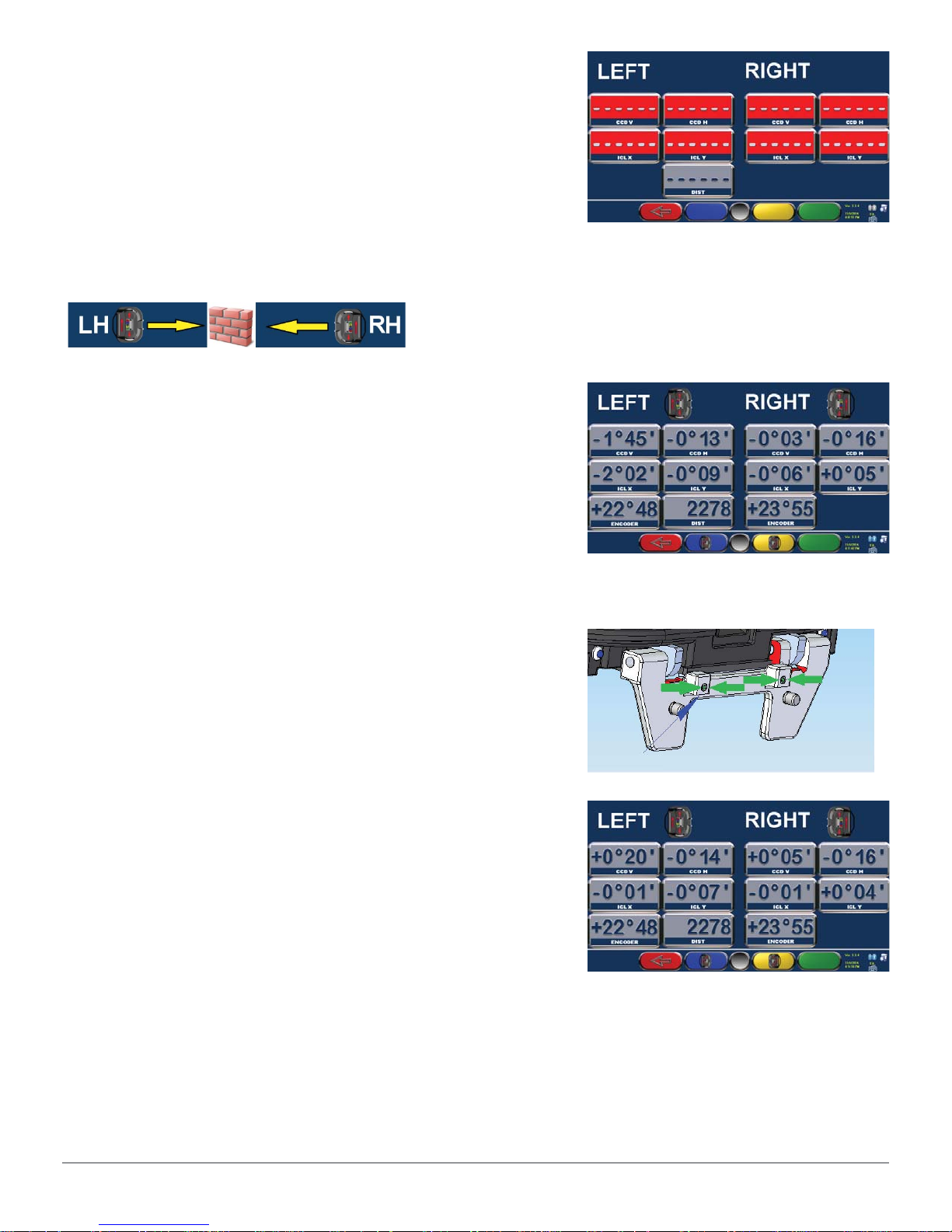
If you do not read any values as in this screen, it
can be caused by:
1) The heads are off - turn them on.
2) The heads are on but there is no Bluetooth
connection, Bluetooth icons appear on the screen
are gray - perform the procedure “Searching for
Bluetooth”
3) The heads are on, the Bluetooth icons are
blue colored (connection established), check that
there are no obstructions between the CCD
Under normal conditions, this page displays the
values. Read the values “ICL X” and “ ICL Y “
of the 2 heads; these are the values of the
inclinometers. ICL Y depends on the accuracy
with which you have been carried out the fixing
holes of the heads support to the lift, the optimal
value is 0:00 degrees but a tolerance of +/- 1
degree is acceptable
The “ICL X” is adjustable, see picture below.
Acting on the Allen screws (size 3) shown in the
figure, bring the values ICL X to 0.00 degrees.
THESE ADJUSTMENTS SHOULD BE MADE
WITH LIFT COMPLETELY DOWN.
After the adjustment of the ICL X values close to
zero (tolerance +/- 0,05 degrees) it is suggested
to lock the adjustment screws by using a special
glue (thread braker).
ADJUSTING THE VERTICAL CCD ON LIFT
This adjustment is used to compensate different heights between the left and
right ramps of the lift. Installations on the floor (in the pit) and lifts who have
ramps at the same height do NOT require this adjustment.
To perform this procedure: Read the service manual.

Quick Start Steps 11
Cyclops
Targets Assembly And Targets Setting
Place one car on the lift stopped with the front
wheels on the turn table.
Fix the clamps on the wheels.
Take care of the vertical arm of the clamp to be
placed to “12 o’clock” as shown in the figure.
In the rear part of the Target, there is a label
which identifies the working position.
There must be at Target FL; FR; RL and RR to
be fixed on their respective wheels (Front Left,
Front Right, Rear Left and Rear Right).
Mount the targets on their clamps.
The filter of the target should be facing the
camera mounted in the measuring head.
For now, do not stop the Target because they
have to be adjusted in accordance to a correct
angle Clamp / Target / Camera.
The settings are made as follows:
Turn on the measuring heads.
Go in front of the monitor and from the logo
page displayed on the right, proceed as follows:
Press the “F2” key (blue)
Press “F2” or “F3” key (blue or yellow) to move
the cursor to “System Configuration”.
Press “F4” to continue.
Filter

Quick Start Steps 12
Cyclops
Press “F2” or “F3” key (blue or yellow) to move the
cursor to “Equipment Configuration”.
Press “F4” to continue.
Press “F2” or “F3” key (blue or yellow) to move the
cursor to “Equipment Configuration”.
Press “F4” to continue.
WE CHECK THAT THE TARGET CODE (ON
BAR CODE STACKED ON THE REAR OF THE
EACH TARGET) MATCHES WITH THE FILES
ENTERED IN THE WHEEL ALIGNMENT PROGRAM
CONFIGURATION.
Press “F2” or “F3” key (blue or yellow) to move the
cursor to the “Target File” Press “F4” to continue.
Check that the names of the Target written on this
page match with the code on the label stacked on
each target, see photo below. The name written here
should match with the file characterization/calibration
of the target and this file is used to correctly read the
angles of the wheels. If the file name is wrong also
file stored on your computer is not correct. Enter
correct code and the right file normally stored on
the USB memory key will be automatically copied on
the wheel aligner program.
The Target files are located in the memory stick that
came with the PC. Check on the memory key, in the
“TARGET” folder, the files stored have the same name
of the target mounted on Clamps. Connect the USB
to the PC.
Referring to the previous image, write the correct
code in each box of the Target if wrong or not
present. When you press the “F1” key to exit this
page, the program will automatically copy the files
from USB to PC, if not already done.

Quick Start Steps 13
Cyclops
This is an example of a “Recovery” key that
came with the wheel alignment containing
the TARGET folder with files.
After pressing “F1” from the target code
page, the program goes back to show the
page here displayed; move the cursor to
“Equipment Configuration” and press “F4”.
Press “F2” or “F3” (blue or yellow) to move
the cursor to “Target Mounting”.
Press “F4” to continue.
We are ready to record and lock the targets in
the clamps in their normal operating position.
Make sure that measuring heads are
turned on.
Check the Targets are fully inserted in
clamps.
With the pin slightly braked, turn the target
until you find the correct position. THE TARGET WHEN REACHED THE
RIGHT POSITION MUST BE LOCKED
Target close to the
correct position, rotate
slowly and lock
Target far from the right
position, please continue
to rotate the target
Target in right
position – lock
Target out of
position or absent

Quick Start Steps 14
Cyclops
What Remains To Be Done? – Last Operations
At this point the wheel aligner is ready for operation.
It remains to choose:
• The measure unit by which you want to display the measurements
(mm, degrees minutes or degrees decimal),
• The resolution of the measured values,
• How you want to display the vehicles database
• You have to write the heading of the client, the address, the phone, to be
saved and printed in the report.
Please consult your service manual and user manual for this information.
Other manuals for Cyclops
1
Table of contents
Other Atlas Wheel Balancer manuals
Popular Wheel Balancer manuals by other brands

Hofmann
Hofmann geodyna 990-2 Operation manual

Corghi
Corghi PROLINE 640 manual

Northwest
Northwest Leica DM6B quick start guide

Titan Lifts
Titan Lifts XL Tool WB-350 factory reset

HENNESSY INDUSTRIES
HENNESSY INDUSTRIES COATS 950 Service Manual and Troubleshooting Guide

M&B Engineering
M&B Engineering WB 255-N Original instructions