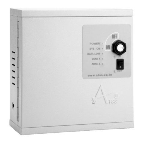
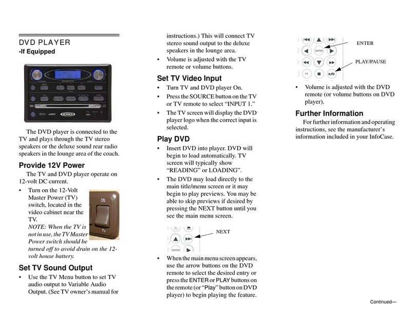
ATSS ACTIVE 207 User manual

ACTIVE 207
USER MANUAL


Optional
Ÿ0-240 Second Delay Time Setting
ŸDaily Alert
ŸArm/Disarm Through password
ŸChangeable User password
ŸAuto Arming Provision For Zones
Ÿ24 Hrs Panic/Tamper Zone
ŸImmediate And Time Delay Zones Available
ŸIndividual Zone password Option
ŸInstant Siren Alert For Zone Open
ŸLED Indicators For Individual Zone Status
ŸTwo Siren With Tamper Provision
ŸModified Siren Out Timing For Short, Long & Infinite
ŸSiren Disconnect Sensing
ŸBuilt In Battery Backup Provision
ŸLow Battery/Reverse Battery Indicators
ŸResettable Fuse
ŸControl Panel Door Tamper
ŸMicro-Controller Based System
ŸWireless Remote
ŸAuto Dialer
Optional
ACTIVE 207FEATURES

Introduction
About your alarm system…
Terms
Operator Controls
...you may need to know
...and indicators
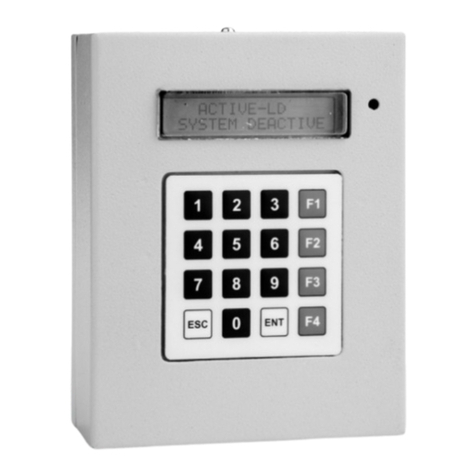
Active 207 is a 2 Zone keypad based Burglar/Intruder alarm
system which provides Comprehensive and flexible protection
for domestic or commercial premises. Zone activation and
deactivation are done through keypad by entering assigned
passwords.
ŸARMING – Activating
ŸDISARMING – Deactivating
ŸZONE – Part of area
ACTIVE 207USER MANUAL
1 2-
12 3 F1
ESC 0 ENT F4
45 6 F2
78 9 F3
6 5
1
2
3
4
7
8
9
10

USER MANUAL
1. F1- Activate Zone 1
Press and enter Zone 1's six digit
password “******” to activate Zone 1.
2. F2- Activate Zone 2
Press and enter Zone 2's six digit
password “******” to activate Zone 2
3. F3- Activate both Zones
Press and enter either Zone 1 or Zone 2's six digit
password “******” to activate both Zone 1 & Zone 2.
4. F4- Enter in to main menu
Press and enter six digit password “******” of Zone
which you want to access to enter in to main menu of that
particular Zone.
5. ENT-Enter
Press to confirm.
6. ESC- Escape
Press to come back of an option.
7. (0-9) – Input Keys
Keys are used to give input values.
F1
ESC
ENT
0-9
F4
F2
F3
Operator Controls ...and indicators 1 2-
ACTIVE 207

USER MANUAL
8. LED 1 Color Indications:
Green - Power indication
Red- Function condition indicator.
Orange – Low battery indication.
Off state – Panic/Tamper alert indication.
9. LED 2 color indications:
Red - Zone 1 in armed state.
Green – Zone 1 in disarmed state.
Blinking in Green – Zone 1 delay time.
Blinking Red & Green – Zone 1 error condition.
10. LED 3 color indications
Red - Zone 2 in armed state.
Green – Zone 2 in disarmed state.
Blinking in Green – Zone 2 delay time.
Blinking Red & Green – Zone 2 error condition.
Operator Controls ...and indicators
…the system
…zone 1
1 2-
ACTIVE 207
ŸPress F1 and enter six digit password “******” of Zone1.
ŸIt will take 60 seconds to arm till then Zone 1 indication LED
will be blinking in Green color.
ŸOnce the Zone 1 is Armed it will start glowing in RED color.
Arming
Arming

USER MANUAL
…zone 2
…all the Zones
…confirmation alert
ACTIVE 207
ŸPress F2 and enter six digit password “******” of Zone 2.
ŸIt will take 60 seconds to arm till then Zone 1 indication LED
will be blinking in Green color.
ŸOnce the Zone 2 is Armed it will start glowing in RED color.
ŸPress F3 and enter six digit password “******”of any one
Zone.
ŸIt will take 60 seconds to arm till then Zone 1& Zone 2
indications LED will be blinking in Green color.
ŸOnce the Zones are Armed both LED will start glowing in RED.
Once you have Armed the Zones, after delay time, you will hear a
confirmation siren sound for few seconds acknowledging that
Zones have been Armed properly.
Arming
Arming
DON'T FORGET
…the system
…zone 1
ŸEnter Zone 1 six digit password “******” directly to Disarm.
ŸZone 1 indication LED 2 will change to green color indicating
that Zone is Disarmed.
Disarming
Disarming

USER MANUAL
…zone 2
…menus
…password
ACTIVE 207
ŸEnter Zone 2 six digit password “******” directly to Disarm.
ŸZone 2 indication LED 3 will change to green color indicating
that Zone is Disarmed.
ŸPress F4 then press the particular Zones password “******” &
then press the following keys below to enter into their menu
respectively.
F1 > EDIT PASSWORD
F2 > TIME DELAY
F3 > SET AUTOZONES
F4> SIREN OUT TIMING
ŸPress F4, LED1 will change to RED color, then Enter particular
Zone six digit “******”password which you want to access.
ŸNow that particular Zone indication LED will change to RED
color.
ŸThen, Press F1 to enter in to edit password menu.
ŸNow enter your new six digit “******”password, you will
hear a double beep sound after it again ,
ŸRe-enter your new 6 digit “******” password now you will
again hear a double beep sound which confirms password
change.
ŸPress ESC to go back.
Edit
Disarming
List of

USER MANUAL
…delay
…auto Zones
ACTIVE 207
You can set time delay from 0-240 seconds. For example if you
set time delay 030 seconds for Zone 1,Zone 1 will take 030
seconds delay time when it is opened, after 030 seconds only
siren will start ringing.
This feature helps you to keep Zones in auto Activation mode.
Once you keep particular Zone in Auto Activation mode it will
automatically activate when the Zone is closed.
ŸPress F4, LED1 will change to RED color, then Enter
particular Zone six digit “******”password which you
want to access.
ŸNow that particular Zone indication LED will change to RED
color.
ŸThen, Press F2 to enter in to time delay menu.
ŸNow Set time delay which you want for particular Zone,
Example: 030 after entering it you will hear double
beep sound which confirms the process.
ŸPress ESC to go back.
ŸPress F4, LED1 will change to RED color, then Enter
particular Zone six digit “******”password which you
want to access.
ŸNow that particular Zone indication LED will change to
RED color.
ŸThen, Press F3 to enter in to set auto Zones menu.
ŸNow press Key 1 to activate Auto Zone
ŸIf you want to deactivate Auto Zone facility for particular
Zone, follow same process as above and press key 2.
ŸNow press ESC to go back.
ŸNote: You can deactivate Zone which is in (Auto Zone
Mode) only when it is in Open state.
Time
Set

USER MANUAL
…out timings
ACTIVE 207
Modify siren out timing.
Once you press any one of the key as listed above you will
hear a confirmation tone (Double beep).
ŸPress F4, LED1 will change to RED color, then Enter
particular Zone six digit “******”password which you
want to access.
ŸNow that particular Zone indication LED will change to RED
color.
ŸThen, Press F4 to enter in to siren out timing menu.
ŸNow press, Key 1 for short Timing
ŸKey 2 for long Timing
ŸKey 3 for infinite Timing
Siren
R E M O T E
A
B
C
D
Remote ...functions
A - ARM the system
B - PANIC
C - RELAY CONTROL
D - DISARM the system

SPECIFICATION ACTIVE 207
POWER SUPPLY
Max Power Consumption
AC Main Supply
Transformer-Step down
BATTERY
Battery type
Max Recharging Voltage-Input
Max Voltage/Current ratings
ZONES
Zone Response Time
Zone Loop Resistance
Max Output Voltage/Current for
Sensor Supply
Max Output Voltage/Current for
Siren Supply
Max Length of Sensor Cable
(multi core cable)
Max Length of Siren Cable
(multi core cable)
RELAY-NORMALLY CLOSED
Max Output Voltage/Current
ENVIRONMENTAL
Environment
Max Humidity
Operating Temperature
Storage Temperature
PHYSICAL
Colour
Control Panel Dimensions(mm)
Weight
36 Watts
220-240 V AC /50 Hz
230 V AC/50 Hz(Pri)
18 V AC /2 A (Sec)
Battery is fully recommended
Lead Acid Rechargeable Battery
13.7 V DC
12 V DC/7 AH
< 500 Millisecond
< 1kilo Ohm For Normally Closed
12 V/500 MA
12 V/750 MA
150 m
(Depends on cable resistance)
75 m
(Depends on cable resistance)
AC 240 V/ 5 A
Residential/ Commercial/
Light Industrial
95% Non-Condensing
0˚C To 45˚C
-20°C~+ 60°C
Grey Coloured Metal Box
(H X W X L)=240 X 90 X 240
2.8 kg

INSTALLATION DIAGRAM ACTIVE 207
+
-
TAMPER
S I R E N S I R E N
+ -
TAMPER
NO
NC
E
M
E
R
G
E
N
C
Y
PA N I C
ALA
+ 12V
- GND
P I R
TAM
DOOR
DOOR SENS ORDO OR S EN SOR
SHUTTER SENSOR
GSM AUTO DIALER
LCD
MIC
MIC
PWR 1NW
PWR 2
N/W
PWR
DOOR JUMPER DOOR TAMPER
AB
GND
KEY PADEX-CONN
EX / RLY
NC COM NO DC 12/24VTRIG - 1TRIG - 2
ANT
ACTIVE - GD
BOARD SIZE
W : 110 mm
H : 110 mm
SIM
INSERT
SPK
LOCKER
D OO R
S E N S O R
SIREN 2 ZONE 2
T T --++
SIREN 1 ZONE 1
T T --++
EX / TG
NO COM NC
PANIC
V VV
V VV
V VV
V VV
MAIN VOLT
BATTERY TRANS - SEC TRANS - PRI
AC 230V SUPPLY
L N E
-+
ZONE 2
ZONE 1
POWER /
LOW BATTERY
DOOR TAMPER
DOOR JUMPER
REMOTE
GND
+5V
10
11
12
13
AB
-
+
KEY PAD
DIALER
ACTIVE - 207
BOARD SIZE
L : 145 mm
H : 85 mm
FIXED
GLASS
GLASS
SENSOR
FRONT
GLASS
DOOR
DOOR SENSOR
R E M O T E
A
B
C
D
Connect to
BATTERY
BUSY
LOW - BATTERY
BATTERY FULL
REVERSE BATTERY
POWER
CHARGING VOLT

WARRANTY CERTIFICATE
Customer Name :
Dealer Seal
Serial No :
Invoice No :
Date :
Signature
How To Obtain Warranty Service?
No.40, Muthumariamman Koil St,
Navalar Nagar, Anna Nagar West,
Chennai - 600 040. India.
ACTIVE 207
You must present your Warranty Card and a copy of your
original sales receipt to validate warranty coverage.
DO NOT lose your receipt.
Table of contents
Other ATSS Security System manuals
Popular Security System manuals by other brands

Honeywell
Honeywell LYNX quick guide

König
König SAS-DUMMYCAM40 manual

Smart Caregiver
Smart Caregiver TL-2100B Installation and use instructions
BT Redcare
BT Redcare Classic Replacement installation guide
DSC
DSC Power832 user manual
Spectrum Technologies
Spectrum Technologies WatchDog Cellular Alert PRO product manual
