Hardware Installation Manual Contents
MSBR Series 5 Mediant 1000B MSBR
List of Figures
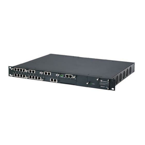
Figure 3-1: Front Panel..........................................................................................................................17
Figure 3-2: FXS Module.........................................................................................................................18
Figure 3-3: FXO Module........................................................................................................................19
Figure 3-4: BRI Module..........................................................................................................................20
Figure 3-5: TRUNKS Module.................................................................................................................21
Figure 3-6: Media Processing Module (MPM).......................................................................................22
Figure 3-7: CRMX Module (Example with WAN GbE) ..........................................................................23
Figure 3-8: Power Supply Module ........................................................................................................25
Figure 3-9: Rear Panel ..........................................................................................................................26
Figure 4-1: Location of Grooves for Rubber Feet..................................................................................27
Figure 4-2: Rear Mounting Brackets Attached to Rear Rack Posts......................................................31
Figure 4-3: Attaching Rear Mounting Bracket Flange to Chassis' Rear-Side Mounting Holes.............31
Figure 4-4: Sliding the Rear Mounting Flanges into the Rear Mounting Brackets................................32
Figure 4-5: Fastening Rear Mounting Flange to Rear Mounting Bracket..............................................32
Figure 4-6: Front Mounting Brackets Flush and Aligned with Front Rack Posts...................................33
Figure 5-1: Grounding the Device..........................................................................................................35
Figure 5-2: RJ-45 Connector Pinouts for WAN Ethernet.......................................................................36
Figure 5-3: Connecting the GbE WAN Port...........................................................................................36
Figure 5-4: Connecting the SFP Fiber Optic WAN Port ........................................................................37
Figure 5-5: Connecting the SHDSL WAN Port......................................................................................38
Figure 5-6: RJ-45 Connector Pinouts for LAN.......................................................................................39
Figure 5-7: Connecting to LAN Ports.....................................................................................................39
Figure 5-8: RJ-11 Connector Pinouts for FXS.......................................................................................40
Figure 5-9: RJ-11 Connector Pinouts for FXO ......................................................................................41
Figure 5-10: RJ-11 Connector Pinouts for Analog Lifeline....................................................................42
Figure 5-11: Cabling the Analog Lifeline ...............................................................................................42
Figure 5-12: Connecting BRI Ports........................................................................................................43
Figure 5-13: RJ-45 Connector Pinouts for BRI......................................................................................43
Figure 5-14: Cabling (Ports 1 and 2) PSTN Fallback............................................................................44
Figure 5-15: RJ-48c Connector Pinouts for E1/T1 ................................................................................45
Figure 5-16: Cabling E1/T1 Trunk Ports................................................................................................45
Figure 5-17: Cabling (Ports 1 and 2) PSTN Fallback............................................................................46
Figure 5-18: Orderable RS-232 Cable Adapter.....................................................................................47
Figure 19: Serial Connection with PC for CLI Communication..............................................................48
Figure 20: Connecting to Power............................................................................................................50
Figure 6-1: Module Chassis Slot Assignment........................................................................................51
Figure 6-2: Recommended Priority Module Slot Assignment (Example).............................................52
Figure 6-3: Kapton Tape Covering Module's Gold Finger....................................................................52
Figure 6-4: Incorrect Slot Insertion for Power Supply Module..............................................................53
Figure 6-5: Removing AMC Modules.....................................................................................................55
Figure 6-6: Module Orientation in Top and Bottom Chassis Slots ........................................................56
Figure A-1: OSN3 Module Ports............................................................................................................58
Figure A-2: RJ-45-to-DB-9 Serial Cable Adapter ..................................................................................59
Figure A-3: OSN3 Module LEDs............................................................................................................59
Figure A-4: OSN4 Module Ports............................................................................................................61
Figure A-5: OSN4 Module LEDs............................................................................................................62
Figure A-6: HDMX Module.....................................................................................................................63
Figure A-7: Cabling OSN3 Module for Installing Linux..........................................................................64
Figure A-8: Cabling OSN4 Module for Installing Linux..........................................................................65
Figure A-9: Cabling OSN3 Module for Remote Desktop Connection from PC with Windows XP........67
Figure A-10: Changing the PC's IP Address .........................................................................................68
Figure A-11: Entering IP Address in Remote Desktop Connection.......................................................68
Figure A-12: Entering User Name and Password in Remote Desktop Connection..............................68


