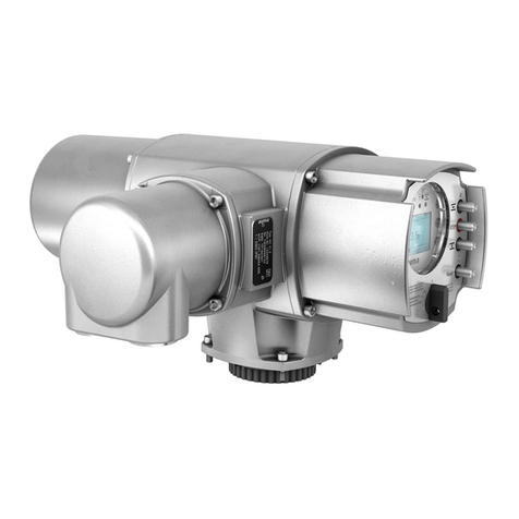
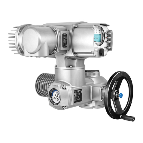
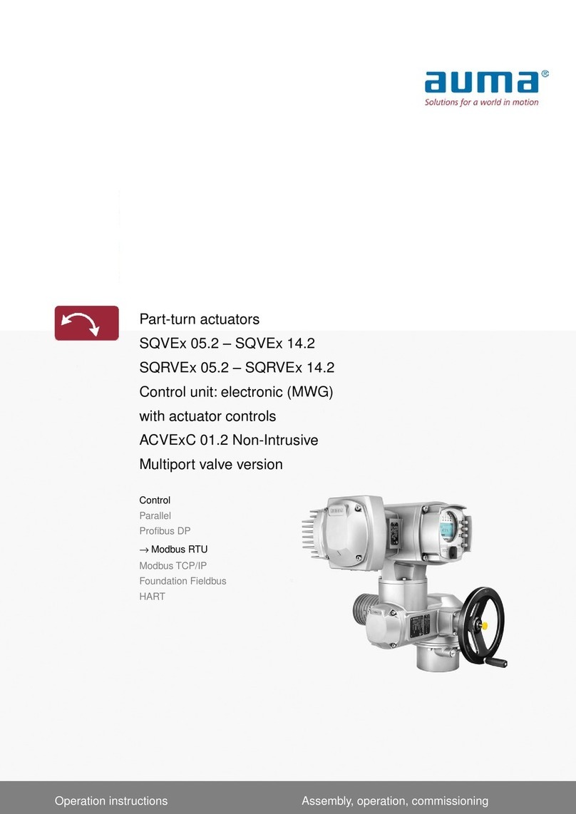
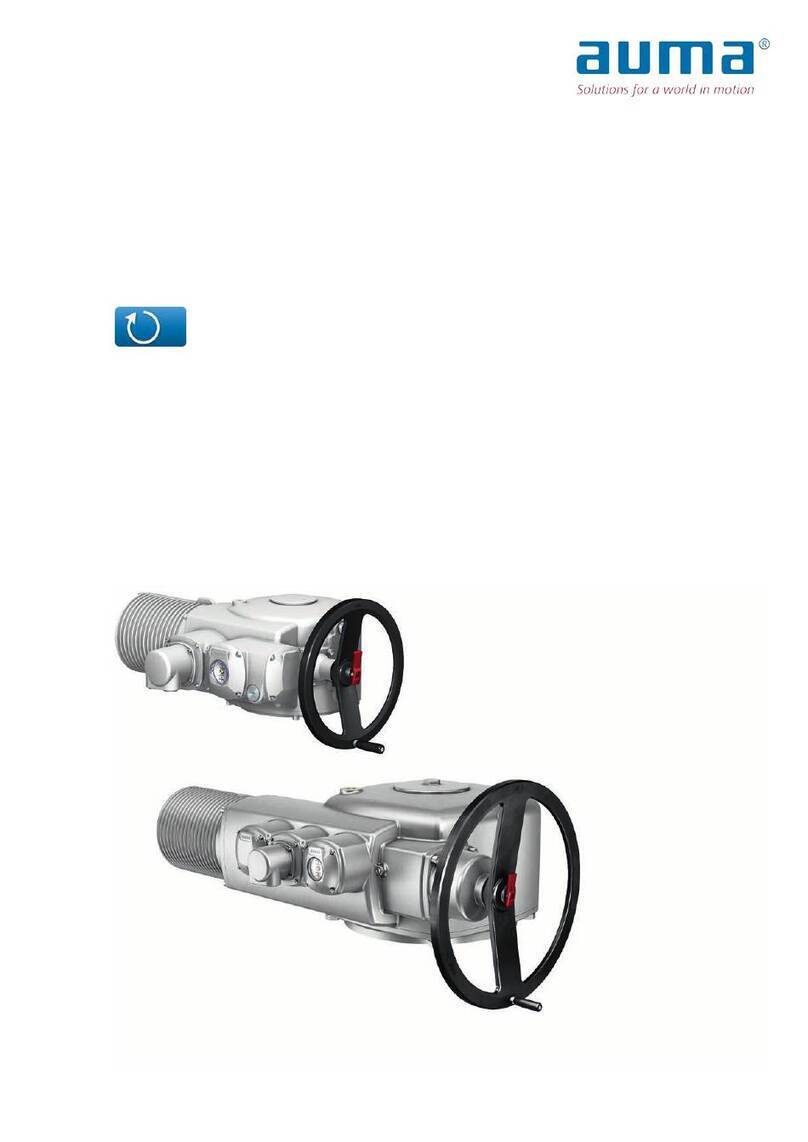
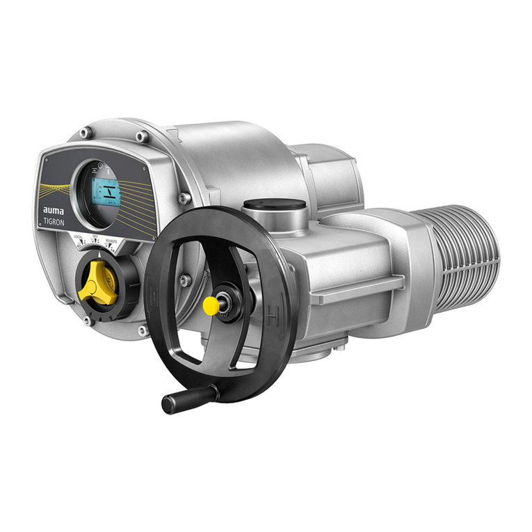
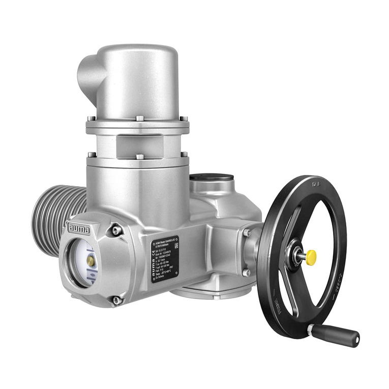
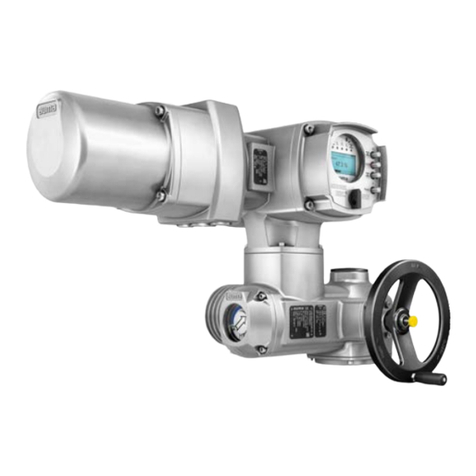
AUMA SA Series User manual

Control
Parallel
Profibus DP
Profinet
Modbus RTU
Modbus TCP/IP
Foundation Fieldbus
→HART
Multi-turn actuators
SA 07.2 –SA 16.2
SAR 07.2 –SAR 16.2
Control unit: electronic (MWG)
with actuator controls
AC 01.2 Non-Intrusive
Assembly, operation, commissioningOperation instructions

Read operation instructions first.
●Observe safety instructions.
●These operation instructions are part of the product.
●Retain operation instructions during product life.
●Pass on instructions to any subsequent user or owner of the product.
Purpose of the document:
This document contains information for installation, commissioning, operation and maintenance staff.It is intended
to support device installation and commissioning.
Reference documents:
●Manual (Operation and setting ) of actuator controls HART
●Manual (Fieldbus device integration) of actuator controls HART
Reference documents can be downloaded from the Internet (www.auma.com) or ordered directly from AUMA
(refer to <Addresses>).
Table of contents Page
51. Safety instructions................................................................................................................. 51.1. Basic information on safety 51.2. Range of application 61.3. Applications in Ex zone 22 (option) 61.4. Warnings and notes 71.5. References and symbols
82. Identification........................................................................................................................... 82.1. Name plate 112.2. Short description
123. Transport, storage and packaging........................................................................................ 123.1. Transport 143.2. Storage 143.3. Packaging
154. Assembly................................................................................................................................ 154.1. Mounting position 154.2. Handwheel fitting 154.3. Multi-turn actuator: mount to valve/gearbox 154.3.1. Output drive type A 164.3.1.1. Stem nut: finish machining 174.3.1.2. Multi-turn actuator (with output drive type A): mount to valve 184.3.2. Output drive types B 194.3.2.1. Multi-turn actuator with output drive types B: mount to valve/gearbox 204.4. Accessories for assembly 204.4.1. Stem protection tube for rising valve stem 214.5. Mounting positions of local controls 214.5.1. Mounting positions: modify
225. Electrical connection............................................................................................................. 225.1. Basic information 245.2. S/SH/SD electrical connection (AUMA plug/socket connector) 265.2.1. Terminal compartment (for mains connection): open
2
SA 07.2 –SA 16.2/SAR 07.2 –SAR 16.2 Control unit: electronic (MWG)
Table of contents AC 01.2 Non-Intrusive HART

275.2.2. Cable connection 295.2.3. Terminal compartment (for mains connection): close 305.2.4. HART terminal compartment: open (version with HART connection board) 315.2.5. HART cables: connect 335.2.6. HART terminal compartment: close (version with HART connection board) 345.3. Accessories for electrical connection 345.3.1. Controls mounted on wall bracket 355.3.2. Parking frame 355.3.3. DS intermediate frame for double sealing 365.3.4. External earth connection
376. Operation................................................................................................................................ 376.1. Manual operation 376.1.1. Engage manual operation 376.1.2. Manual operation: disengage 386.2. Motor operation 386.2.1. Local actuator operation 396.2.2. Actuator operation from remote 396.3. Menu navigation via push buttons (for settings and indications) 406.3.1. Menu layout and navigation 416.4. User level, password 416.4.1. Password entry 426.4.2. Password change 426.5. Language in the display 436.5.1. Language change
447. Indications.............................................................................................................................. 447.1. Indications during commissioning 447.2. Indications in the display 457.2.1. Feedback indications from actuator and valve 487.2.2. Status indications according to AUMA classification 487.2.3. Status indications according to NAMUR recommendation 507.3. Indication lights of local controls 517.4. Optional indications 517.4.1. Mechanical position indication (self-adjusting) 517.4.2. Mechanical position indication via indicator mark
528. Signals (output signals)......................................................................................................... 528.1. Signals via HART 528.2. Status signals via output contacts (digital outputs) 528.2.1. Assignment of outputs 528.2.2. Coding the outputs 528.3. Analogue signals (analogue outputs)
539. Commissioning (basic settings)........................................................................................... 539.1. Type of seating: set 549.2. Torque switching: set 559.3. Limit switching: set 579.4. HART address (slave address):set 589.5. Test run 589.5.1. Direction of rotation at mechanical position indicator: check 599.5.2. Direction of rotation at hollow shaft/stem: check 609.5.3. Limit switching: check
3
SA 07.2 –SA 16.2/SAR 07.2 –SAR 16.2 Control unit: electronic (MWG)
AC 01.2 Non-Intrusive HART Table of contents

6110. Commissioning (settings/options in the actuator)............................................................. 6110.1. Switch compartment: open/close 6210.2. Mechanical position indicator (self-adjusting) 6210.2.1. Mechanical position indicator: set 6310.2.2. Gear stage of the reduction gearing: test/set 6410.3. Mechanical position indication via indicator mark (not self-adjusting) 6410.3.1. Mechanical position indicator: set 6410.3.2. Gear stage of the reduction gearing: test/set
6711. Corrective action.................................................................................................................... 6711.1. Faults during commissioning 6711.2. Fault indications and warning indications 7111.3. Fuses 7111.3.1. Fuses within the actuator controls 7311.3.2. Motor protection (thermal monitoring)
7412. Servicing and maintenance................................................................................................... 7412.1. Preventive measures for servicing and safe operation 7412.2. Maintenance 7512.3. Disposal and recycling
7613. Technical data......................................................................................................................... 7613.1. Technical data Multi-turn actuators 7813.2. Technical data Actuator controls
8514. Spare parts............................................................................................................................. 8514.1. Multi-turn actuators SA 07.2 –SA 16.2/SAR 07.2 –SAR 16.2 8714.2. AC 01.2 actuator controls 8914.3. Actuator controls AC 01.2 - Fieldbus
9115. Certificates.............................................................................................................................. 9115.1. Declaration of Incorporation and EU Declaration of Conformity
94Index........................................................................................................................................
97Addresses...............................................................................................................................
4
SA 07.2 –SA 16.2/SAR 07.2 –SAR 16.2 Control unit: electronic (MWG)
Table of contents AC 01.2 Non-Intrusive HART

1. Safety instructions
1.1. Basic information on safety
Standards/directives Our products are designed and manufactured in compliance with recognised
standards and directives.This is certified in a Declaration of Incorporation and an
EU Declaration of Conformity.
The end user or the contractor must ensure that all legal requirements, directives,
guidelines, national regulations and recommendations with respect to assembly,
electrical connection, commissioning and operation are met at the place of installation.
Safetyinstructions/warn-
ings All personnel working with this device must be familiar with the safety and warning
instructions in this manual and observe the instructions given. Safety instructions
and warning signs on the device must be observed to avoid personal injury or property
damage.
Qualification of staff Assembly, electrical connection, commissioning, operation, and maintenance must
be carried out by suitably qualified personnel authorised by the end user or contractor
of the plant only.
Prior to working on this product, the staff must have thoroughly read and understood
these instructions and, furthermore, know and observe officially recognised rules
regarding occupational health and safety.
Commissioning Prior to commissioning, it is important to check that all settings meet the requirements
of the application. Incorrect settings might present a danger to the application, e.g.
cause damage to the valve or the installation.The manufacturer will not be held
liable for any consequential damage. Such risk lies entirely with the user.
Operation Prerequisites for safe and smooth operation:
●Correct transport, proper storage, mounting and installation, as well as careful
commissioning.
●Only operate the device if it is in perfect condition while observing these instruc-
tions.
●Immediately report any faults and damage and allow for corrective measures.
●Observe recognised rules for occupational health and safety.
●Observe national regulations.
●During operation,thehousing warms upandsurfacetemperatures >60°C may
occur.To prevent possible burns, we recommend checking the surface temper-
ature using an appropriate thermometer and wearing protective gloves, if re-
quired, prior to working on the device.
Protective measures The end user or the contractor are responsible for implementing required protective
measures on site, such as enclosures, barriers, or personal protective equipment
for the staff.
Maintenance To ensure safe device operation, the maintenance instructions included in this manual
must be observed.
Any device modification requires prior written consent of the manufacturer.
1.2. Range of application
AUMA multi-turn actuators are designed for the operation of industrial valves, e.g.
globe valves, gate valves, butterfly valves, and ball valves.
Other applications require explicit (written) confirmation by the manufacturer.
The following applications are not permitted, e.g.:
●Industrial trucks according to EN ISO 3691
●Lifting appliances according to EN 14502
●Passenger lifts according to DIN 15306 and 15309
●Service lifts according to EN 81-1/A1
5
SA 07.2 –SA 16.2/SAR 07.2 –SAR 16.2 Control unit: electronic (MWG)
AC 01.2 Non-Intrusive HART Safety instructions

●Escalators
●Continuous duty
●Buried service
●Continuous submersion (observe enclosure protection)
●Potentially explosive areas, with the exception of zone 22
●Radiation exposed areas in nuclear power plants
No liability can be assumed for inappropriate or unintended use.
Observance of these operation instructions is considered as part of the device's
designated use.
Information These operation instructions are only valid for the "clockwise closing" standard
version, i.e. driven shaft turns clockwise to close the valve.
1.3. Applications in Ex zone 22 (option)
Actuators of the indicated series basically meet the requirements for applications in
dust hazardous locations of ZONE 22 in compliance with the ATEX directive
2014/34/EU.
To comply with all requirements of the ATEX directive, observe the following points:
●Actuators are marked with the explosion protection designation II3D... for use
in ZONE 22.
●Maximum surface temperature of actuators
- T150 °C for ambient temperatures up to +60 °C or
- T190 °C for ambient temperatures up to +80 °C.
Increased dust deposit on the equipment was not considered for the determin-
ation of the maximum surface temperature.
●The following conditions must be fulfilled to respect the maximum permissible
surface temperatures at the actuator:
- Respecting types of duty and technical manufacturer data
- Correct connection of thermal motor protection (thermoswitches or PTC
thermistor)
Maximum
surface temperature
Tripping temperature
Thermal motor protection
Ambient temperature
T150 °C140 °Cup to +60 °C T190 °C155 °Cup to +80 °C
●The connector may only be connected or disconnected when not live.
●The cable glands and cable entries used have to meet the requirements of
category II3D and must at least comply with enclosure protection IP67.
●The actuators must be connected by means of an external earth connection
(accessory part) to the equipotential earth bonding or integrated into an earthed
piping system.
●To ensure combustible dust hazard protection, seal hollow shaft against ingress
of dust:
- Using threaded plug (ref. no. 511.0) and appropriate seal
- Using metallic stem protection tube, protective cap and V-seal (ref. no.
568.1, 568.2, 568.3) for rising valve stem
●As a general rule, the requirements of IEC 60079 Parts 14 and 17 must be re-
spected in dust hazardous locations.During commissioning, service, and
maintenance, special care as well as qualified and trained personnel are required
for safe actuator operation.
1.4. Warnings and notes
The following warnings draw special attention to safety-relevant procedures in these
operation instructions, each marked by the appropriate signal word (DANGER,
WARNING, CAUTION, NOTICE).
6
SA 07.2 –SA 16.2/SAR 07.2 –SAR 16.2 Control unit: electronic (MWG)
Safety instructions AC 01.2 Non-Intrusive HART

Indicates an imminently hazardous situation with a high level of risk. Failure
to observe this warning could result in death or serious injury.
Indicates a potentially hazardous situation with a medium level of risk.Failure
to observe this warning could result in death or serious injury.
Indicates a potentially hazardous situation with a low level of risk. Failure to
observe this warning could result in minor or moderate injury. May also be
used with property damage.
Potentially hazardous situation. Failure to observe this warning could result
in property damage. Is not used for personal injury.
Arrangement and typographic structure of the warnings
Type of hazard and respective source!
Potential consequence(s) in case of non-observance (option)
→Measures to avoid the danger
→Further measure(s)
Safety alert symbol warns of a potential personal injury hazard.
The signal word (here: DANGER) indicates the level of hazard.
1.5. References and symbols
The following references and symbols are used in these instructions:
Information The term Information preceding the text indicates important notes and information.
Symbol for CLOSED (valve closed)
Symbol for OPEN (valve open)
Important information before the next step.This symbol indicates what is required
for the next step or what has to be prepared or observed.
Via the menu to parameter
Describes the path within the menu to the parameter. By using the push buttons of
the local controls you may quickly find the desired parameter in the display.
< > Reference to other sections
Terms in brackets shown above refer to other sections of the document which provide
further information on this topic.These terms are either listed in the index, a heading
or in the table of contents and may easily be located.
7
SA 07.2 –SA 16.2/SAR 07.2 –SAR 16.2 Control unit: electronic (MWG)
AC 01.2 Non-Intrusive HART Safety instructions

2. Identification
2.1. Name plate
Figure 1: Arrangement of name plates
[1] Actuator name plate
[2] Actuator controls name plate
[3] Motor name plate
[4] Additional plate, e.g. KKS plate (Power Plant Classification System)
Actuator name plate
Figure 2: Actuator name plate (example)
(= manufacturer logo); (= CE mark)
[1] Name of manufacturer
[2] Address of manufacturer
[3] Type designation
[4] Order number
[5] Serial number
[6] Speed
[7] Torque range in direction CLOSE
[8] Torque range in direction OPEN
[9] Type of lubricant
[10] Permissible ambient temperature
[11] Can be assigned as an option upon customer request
[12] Enclosure protection
[13] Data Matrix code
8
SA 07.2 –SA 16.2/SAR 07.2 –SAR 16.2 Control unit: electronic (MWG)
Identification AC 01.2 Non-Intrusive HART

Name plate for actuator controls (example)
Figure 3: Name plate for actuator controls (example)
[1] Type designation
[2] Order number
[3] Serial number
[4] Actuator terminal plan
[5] Actuator controls terminal plan
[6] Mains voltage
[7] AUMA power class for switchgear
[8] Permissible ambient temperature
[9] Enclosure protection
[10] Control
[11] Data Matrix code
Motor name plate
Figure 4: Motor name plate (example)
(= manufacturer logo); (= CE mark)
[1] Motor type
[2] Motor article number
[3] Serial number
[4] Current type, mains voltage
[5] Rated power
[6] Rated current
[7] Type of duty
[8] Enclosure protection
[9] Motor protection (temperature protection)
[10] Insulation class
[11] Speed
[12] Power factor cos phi
[13] Mains frequency
[14] Data Matrix code
9
SA 07.2 –SA 16.2/SAR 07.2 –SAR 16.2 Control unit: electronic (MWG)
AC 01.2 Non-Intrusive HART Identification

Descriptions referring to name plate indications
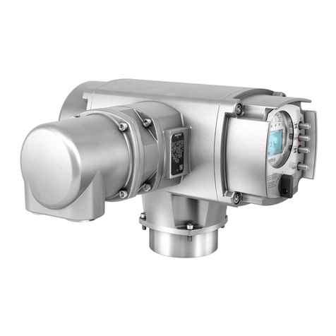
Type designation Figure 5:Type designation (example)
1. Type and size of actuator
2. Flange size
Type and size
These instructions apply to the following devices types and sizes:
●SA.....= Type = Multi-turn actuator for open-close duty
Sizes and generation: 07.2, 07.6, 10.2, 14.2, 14.6, 16.2
●SAR.... = Type = Multi-turn actuator for modulating duty
Sizes and generation: 07.2, 07.6, 10.2, 14.2, 14.6, 16.2
●AC = Type = AC actuator controls
Size and generation:01.2
Order number The product can be identified using this number and the technical data as well as
order-related data pertaining to the device can be requested.
Please always state this number for any product inquiries.
On the Internet at http://www.auma.com > Service & Support >myAUMA, we offer
a service allowing authorised users to download order-related documents such as
wiring diagramsandtechnical data (both inGerman and English), inspectioncertificate
and the operation instructions when entering the order number.
Actuator serial number Table 1:
Description of serial number (with example 0516MD12345)
MD123451605
Positions 1+2: Assembly in week = week 0505
Positions 3+4:Year of manufacture = 201616
Internal number for unambiguous product identificationMD12345
Actuator terminal plan Position 9 after TPA: Position transmitter version
I, Q = MWG (magnetic limit and torque transmitter)
AUMA power class for
switchgear The switchgear used in the actuator controls (reversing contactors/thyristors) are
classified according to AUMA power classes (e.g.A1, B1, ....).The power class
defines the max. permissible rated power (of the motor) the switchgear has been
designed for.The rated power (nominal power) of the actuator motor is indicated in
kW on the motor name plate.For the assignment of the AUMA power classes to the
nominal power of the motor types, refer to the separate electrical data sheets.
For switchgear without assignment to any power classes, the actuator controls name
plate does not indicate the power class but the max. rated power in kW.
Control Table 2:
Control examples (indications on actuator controls name plate)
DescriptionInput signal
Control via HART interfaceHART
Control via HART interface and control voltage for OPEN-CLOSE control via
digital inputs (OPEN, STOP, CLOSE)
HART/24 V DC
Data Matrix code When registered as authorised user, you may use the AUMA Support App to scan
the Data Matrix code and directly access the order-related product documents without
having to enter order number or serial number.
10
SA 07.2 –SA 16.2/SAR 07.2 –SAR 16.2 Control unit: electronic (MWG)
Identification AC 01.2 Non-Intrusive HART

Figure 6: Link to the AUMA App:
For further Service & Support, software/apps/...refer to www.auma.com.
2.2. Short description
Multi-turn actuator Definition in compliance with EN 15714-2/EN ISO 5210:
A multi-turn actuator is an actuator which transmits torque to a valve for at least one
full revolution.It is capable of withstanding thrust.
AUMA multi-turn actuators are driven by an electric motor and are capable of
withstanding thrust in combination with output drive type A. For manual operation,
a handwheel is provided.Switching off in end positions may be either by limit or
torque seating. Actuator controls are required to operate or process the actuator
signals.
Actuator controls actuator controls are used to operate AUMA actuators and are supplied ready for
use.The actuator controls may be mounted directly to the actuator or separately on
a wall bracket.
The functions of the actuator controls include standard valve control in OPEN-CLOSE
duty, positioning, process control, logging of operating data, diagnostic functions
right through control via various interfaces (e.g. Fieldbus, Ethernet and HART).
Local controls/
AUMA CDT Operation, setting, and display can be performed directly at the actuator controls or
alternatively from REMOTE via a fieldbus interface.
When set to local control, it is possible to
●operate the actuator via the local controls (push buttons and display) and perform
settings (contents of these instructions).
●read in or out data or modify and save settings via AUMA CDT software (ac-
cessory), using a computer (laptop or PC).The connection between computer
and actuator controls is wireless via Bluetooth interface (not included in these
instructions).
Intrusive - Non-Intrusive ●Intrusive version (control unit: electromechanical):
Limit and torque setting is performed via switches in the actuator.
●Non-Intrusive version (control unit: electronic):
Limit and torque setting is performed via the controls, without removal of actu-
ator or actuator controls covers.For this purpose, the actuator is equipped with
anMWG(magneticlimitand torque transmitter),alsocapable tosupplyanalogue
torque feedback signals/torque indication and analogue position feedback sig-
nals/position indication at the actuator controls output.
11
SA 07.2 –SA 16.2/SAR 07.2 –SAR 16.2 Control unit: electronic (MWG)
AC 01.2 Non-Intrusive HART Identification

3. Transport, storage and packaging
3.1. Transport
For transport to place of installation, use sturdy packaging.
Hovering load!
Risk of death or serious injury.
→Do NOT stand below hovering load.
→Attach ropes or hooks for the purpose of lifting by hoist only to housing and NOT
to handwheel.
→Actuators mounted on valves: Attach ropes or hooks for the purpose of lifting
by hoist to valve and NOT to actuator.
→Actuatorsmountedtogearboxes:Attachropes orhooks forthe purposeof lifting
by hoist only to the gearbox using eyebolts and NOT to the actuator.
→Actuators mounted to controls: Attach ropes or hooks for the purpose of lifting
by hoist only to the actuator and NOT to the controls.
→Respect total weight of combination (actuator, actuator controls, gearbox, valve)
→Secure load against falling down, sliding or tilting.
→Perform lift trial at low height to eliminate any potential danger e.g.by tilting.
Figure 7: Example: Lifting the actuator
Table 3:
Weights for multi-turn actuators SA 07.2 –SA 16.2 / SAR 07.2 –SAR 16.2
with 3-phase AC motors
Weight2)
Motor type1)
Type designation
Actuator approx. [kg]
19VD...SA 07.2/
SAR 07.2 20AD...
20VD...SA 07.6/
SAR 07.6 21AD...
22VD...SA 10.2/
SAR 10.2 25AD...
44VD...SA 14.2/
SAR 14.2 48AD...
12
SA 07.2 –SA 16.2/SAR 07.2 –SAR 16.2 Control unit: electronic (MWG)
Transport, storage and packaging AC 01.2 Non-Intrusive HART

Weights for multi-turn actuators SA 07.2 –SA 16.2 / SAR 07.2 –SAR 16.2
with 3-phase AC motors
Weight2)
Motor type1)
Type designation
Actuator approx. [kg]
46VD...SA 14.6/
SAR 14.6 53AD...
67VD...SA 16.2/
SAR 16.2 83AD...
Refer to motor name plate1) Indicated weight includes AUMA NORM multi-turn actuator with 3-phase AC motor, electrical con-
nection in standard version, output drive type B1 and handwheel.For other output drive types, heed
additional weights.
2)
Table 4:
Weights for multi-turn actuators SA 07.2 –SA 16.2 / SAR 07.2 –SAR 16.2
With 1-phase AC motors
Weight2)
Motor type1)
Type designation
Actuator approx. [kg]
25VE...SA 07.2/
SAR 07.2 28AE...
25VE...SA 07.6/
SAR 07.6 28AE...
37AC...
28VE...48-4...SA 10.2/
SAR 10.2 31VE...48-2...
40AC... 56-4...
43AC... 56-2...
59VE...SA 14.2/
SAR 14.2 61VC...
63AC...
63VE...SA 14.6/
SAR 14.6 66VC...
Refer to motor name plate1) Indicated weight includes AUMA NORM multi-turn actuator with 1-phase AC motor, electrical con-
nection in standard version, output drive type B1 and handwheel.For other output drive types, heed
additional weights.
2)
Table 5:
Weights for multi-turn actuators SA 07.2 –SA 16.2 / SAR 07.2 –SAR 16.2
With DC motors
Weight2)
Motor type1)
Type designation
Actuator approx. [kg]
29FN... 63-...SA 07.2/
SAR 07.2 32FN... 71-...
30FN... 63-...SA 07.6/
SAR 07.6 44FN... 80-...
33FN... 63-...SA 10.2/
SAR 10.2 36FN... 71-...
56FN... 90-...
68FN... 71-... / FN... 80-...SA 14.2/
SAR 14.2 100FN... 90-...
13
SA 07.2 –SA 16.2/SAR 07.2 –SAR 16.2 Control unit: electronic (MWG)
AC 01.2 Non-Intrusive HART Transport, storage and packaging

Weights for multi-turn actuators SA 07.2 –SA 16.2 / SAR 07.2 –SAR 16.2
With DC motors
Weight2)
Motor type1)
Type designation
Actuator approx. [kg]
76FN... 80-... / FN... 90-...SA 14.6/
SAR 14.6 122FN... 112-...
123FN... 100-...SA 16.2/
SAR 16.2
Refer to motor name plate1) Indicated weight includes AUMA NORM multi-turn actuator with DC motor, electrical connection in
standard version, output drive type B1 and handwheel.For other output drive types, heed additional
weights.
2)
Table 6:
Weights for output drive type A 07.2 –A 16.2
[kg]Flange sizeType designation
1.1F07A 07.2
1.3F10
2.8F10A 10.2
6.8F14A 14.2
11.7F16A 16.2
3.2. Storage
Danger of corrosion due to inappropriate storage!
→Store in a well-ventilated, dry room.
→Protect against floor dampness by storage on a shelf or on a wooden pallet.
→Cover to protect against dust and dirt.
→Apply suitable corrosion protection agent to uncoated surfaces.
Damage on display caused by temperatures below permissible level!
→AC actuator controls MUST NOT be stored below –30 °C.
Long-term storage For long-term storage (more than 6 months), observe the following points:
1. Prior to storage:
Protect uncoated surfaces, in particular the output drive parts and mounting
surface, with long-term corrosion protection agent.
2. At an interval of approx. 6 months:
Check for corrosion.If first signs of corrosion show, apply new corrosion protec-
tion.
3.3. Packaging
Our products are protected by special packaging for transport when leaving the
factory.The packaging consists of environmentally friendly materials which can easily
be separated and recycled.We use the following packaging materials: wood,
cardboard, paper, and PE foil.For the disposal of the packaging material, we
recommend recycling and collection centres.
14
SA 07.2 –SA 16.2/SAR 07.2 –SAR 16.2 Control unit: electronic (MWG)
Transport, storage and packaging AC 01.2 Non-Intrusive HART

4. Assembly
4.1. Mounting position
The product described in this document can be operated in any mounting position.
Restriction:When using oil instead of grease within the actuator gear housing, the
hollow shaft mounting position must be perpendicular, with the flange pointing
downward.The type of lubricant used is indicated on the actuator name plate (short
designation F...= grease; O...= oil).
4.2. Handwheel fitting
Information For transportreason,handwheels witha diameterof 400mm andlarger aresupplied
separately within the scope of delivery.
Figure 8: Handwheel
[1] Spacer
[2] Input shaft
[3] Handwheel
[4] Retaining ring
1. If required, fit spacer [1] on input shaft [2].
2. Slip handwheel [3] onto input shaft.
3. Secure handwheel [3] using the retaining ring [4] supplied.
Information The retaining ring [4] (together with these operation instructions) is stored in a
weatherproof bag, which is attached to the device prior to delivery.
4.3. Multi-turn actuator: mount to valve/gearbox
Danger of corrosion due to damage to paint finish and condensation!
→Touch up damage to paint finish after work on the device.
→After mounting, connect the device immediately to electrical mains to ensure
that heater minimises condensation.
4.3.1. Output drive type A
Application ●Output drive for rising, non-rotating valve stem
●Capable of withstanding thrust
15
SA 07.2 –SA 16.2/SAR 07.2 –SAR 16.2 Control unit: electronic (MWG)
AC 01.2 Non-Intrusive HART Assembly

Design Output mounting flange [1] with axial bearing stem nut [2] form one unit.Torque is
transmitted to valve stem [3] via stem nut [2].
Figure 9: Design of output drive type A
[1] Output mounting flange
[2] Stem nut with dog coupling
[3] Valve stem
Information To adapt the actuators to available output drive types A with flanges F10 and F14
(year of manufacture:2009 and earlier), an adapter is required.The adapter can be
ordered from AUMA.
4.3.1.1. Stem nut: finish machining
✔This working step is only required if stem nut is supplied unbored or with pilot
bore.
Figure 10: Output drive type A
[1] Stem nut
[2] Axial needle roller bearing
[2.1] Axial bearing washer
[2.2] Axial needle roller and cage assembly
[3] Spigot ring
1. Remove spigot ring [3] from output drive.
2. Remove stem nut [1] together with axial needle roller bearings [2].
16
SA 07.2 –SA 16.2/SAR 07.2 –SAR 16.2 Control unit: electronic (MWG)
Assembly AC 01.2 Non-Intrusive HART

3. Remove axial bearing washers [2.1] and axial needle roller and cage assemblies
[2.2] from stem nut [1].
4. Drill and bore stem nut [1] and cut thread.
Information: When fixing in the chuck, make sure stem nut runs true!
5. Clean the machined stem nut [1].
6. Apply sufficient Lithium soap EP multi-purpose grease to axial needle roller and
cage assemblies [2.2] and axial bearing washers [2.1], ensuring that all hollow
spaces are filled with grease.
7. Place greased axial needle roller and cage assemblies [2.2] and axial bearing
washers [2.1] onto stem nut [1].
8. Re-insert stem nut [1] with bearings [2] into output drive.
Information: Ensure that dogs or splines are placed correctly in the keyway of
the hollow shaft.
9. Screw in spigot ring [3] until it is firm against the shoulder.
4.3.1.2. Multi-turn actuator (with output drive type A): mount to valve
Figure 11: Assembly of output drive type A
[1] Valve stem
[2] Output drive type A
[3] Screws to actuator
[4] Valve flange
[5] Screws to output drive
1. If the output drive type A is already mounted to the multi-turn actuator:Loosen
screws [3] and remove output drive type A [2].
2. Check if the flange of output drive type A matches the valve flange [4].
3. Apply a small quantity of grease to the valve stem [1].
4. Place output drive type A on valve stem and turn until it is flush on the valve
flange.
5. Turn output drive type A until alignment of the fixing holes.
6. Screw in fastening screws [5], however do not completely tighten.
7. Fit multi-turn actuator on the valve stem so that the stem nut dogs engage into
the output drive sleeve.
➥The flanges are flush with each other if properly engaged.
8. Adjust multi-turn actuator until alignment of the fixing holes.
9. Fasten multi-turn actuator with screws [3].
17
SA 07.2 –SA 16.2/SAR 07.2 –SAR 16.2 Control unit: electronic (MWG)
AC 01.2 Non-Intrusive HART Assembly

10. Fasten screws [3] crosswise with a torque according to table.
Table 7:
Tightening torques for screws
Tightening torque [Nm]Threads
Strength class A2-80/A4–80
10M6
24M8
48M10
82M12
200M16
392M20
11. Turn multi-turn actuator with handwheel in direction OPEN until valve flange
and output drive A are firmly placed together.
12. Tighten fastening screws [5] between valve and output drive type A crosswise
applying a torque according to table.
4.3.2. Output drive types B
Application ●For rotating, non-rising valve stem
●Not capable of withstanding thrust
Design Connection between hollow shaft and valve or gearbox via output drive sleeve fixed
to the hollow shaft of the multi-turn actuator via retaining ring.
When exchanging the output drive sleeve, later retrofitting to a different output drive
type is possible
●Output drive type B: Output drive sleeve with bore according to DIN 3210
●Output drive types B1 –B4:Output drive sleeve with bore according to EN ISO
5210
Figure 12: Output drive type B
[1] Flange multi-turn actuator (e.g. F07)
[2] Hollow shaft
[3] Output drive sleeve (illustration examples)
[3] B/B1/B2 and [3]* B3/B4, respectively with bore and keyway)
[4] Gearbox/valve shaft with parallel key
18
SA 07.2 –SA 16.2/SAR 07.2 –SAR 16.2 Control unit: electronic (MWG)
Assembly AC 01.2 Non-Intrusive HART

Information Spigot at valve flanges should be loose fit.
4.3.2.1. Multi-turn actuator with output drive types B: mount to valve/gearbox
Figure 13: Mounting output drive types B
[1] Multi-turn actuator
[2] Valve/gearbox
[3] Valve/gearbox shaft
1. Check if mounting flanges fit together.
2. Check if output drive of multi-turn actuator [1] matches the output drive of
valve/gearbox or valve/gearbox valve shaft [2/3].
3. Apply a small quantity of grease to the valve or gearbox shaft [3].
4. Fit multi-turn actuator [1].
Information: Ensure that the spigot fits uniformly in the recess and that the
mounting faces are in complete contact.
5. Fasten multi-turn actuator with screws according to table.
Information: We recommend applying liquid thread sealing material to the
screws to avoid contact corrosion.
6. Fasten screws crosswise to a torque according to table.
Table 8:
Tightening torques for screws
Tightening torque [Nm]Threads
Strength class A2-80/A4–80
10M6
24M8
48M10
82M12
200M16
392M20
19
SA 07.2 –SA 16.2/SAR 07.2 –SAR 16.2 Control unit: electronic (MWG)
AC 01.2 Non-Intrusive HART Assembly

4.4. Accessories for assembly
4.4.1. Stem protection tube for rising valve stem
Figure 14: Assembly of the stem protection tube
[1] Protective cap for stem protection tube (fitted)
[1]* Option: Protective cap made of steel (screwed)
[2] Stem protection tube
[3] V-seal
1. Seal all threads with hemp,Teflon tape, or thread sealing material.
2. Screw stem protection tube [2] into thread and tighten it firmly.
Information: For stem protection tubes made of two or more segments, all
parts have to be thoroughly screwed together.
Figure 15: Protection tube made of segments with threaded sleeves (>900 mm)
[2] Segment of stem protection tube
[3] V-seal
[4] Threaded sleeve
3. Push down the sealing ring [3] onto the housing.
Information: For mounting segments, push down seals of segments down to
the sleeve (connecting piece).
4. Check whether protective cap [1] for stem protection tube is available, in perfect
condition and tightly placed on or screwed to the tube.
Risk of bending or oscillation of protection tubes exceeding a length of 2 m!
Risk of damage at stem and/or protection tube.
→Secure protection tubes exceeding 2 m by an appropriate support.
20
SA 07.2 –SA 16.2/SAR 07.2 –SAR 16.2 Control unit: electronic (MWG)
Assembly AC 01.2 Non-Intrusive HART
Other manuals for SA Series
3
This manual suits for next models
13
Table of contents
Other AUMA Controllers manuals

AUMA
AUMA SG 05.1-F05 User manual

AUMA
AUMA SA 16.2 User manual

AUMA
AUMA VARIOMATIC SARV 10.1 User manual

AUMA
AUMA SA 07.1 Administrator Guide

AUMA
AUMA PROFOX PF-Q80 User manual

AUMA
AUMA SAExC 07.1 User manual

AUMA
AUMA Aumatic ACExC 01.1 User manual

AUMA
AUMA SQ 05.2 User manual

AUMA
AUMA SAEx 07.2 User manual

AUMA
AUMA SA 48.1 User manual