manuals.online logo
Brands
  1. Home
  2. •
  3. Brands
  4. •
  5. Emerson
  6. •
  7. Controllers
  8. •
  9. Emerson FD113 User manual

Emerson FD113 User manual

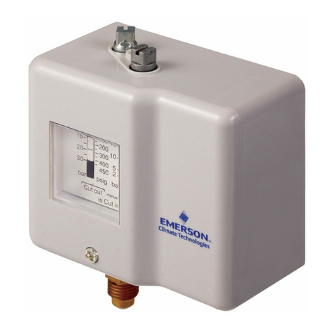
FD113 Oil Pressure Safety Control
Instruction Sheet
PA-00250
June 2013
THE FLEXIBLE CONTROL
• TheFD113OilPressureSafetyControlsensestheeffectiveoil
pressuredifferentialincompressorswithpositivedisplacementoil
pumps.Ifinadequateoilpressureexists,atimedelayisenergized.
Iftheoilpressuredoesnotrecovertosafelevelswithinthetime
delaysetting,thecompressorisshutdown.Thetimedelayallows
thecompressoradequatetimetoestablishoilpressureonstart–up
andavoidsnuisanceshutdownsonpressuredropofshortduration
duringtheruncycle.
• Maximumapplicationexibilityisassuredbyprovidingan
adjustabledifferentialpressureswitchwhichcanbeadjustedto
thecompressor’sminimumrequiredoilpressureneedsandan
adjustabletimedelaywhichallowsyoutoselectthelengthof
timethecompressorrunsbelowtheminimumpressurebefore
shutdown.Theminimumpressuresettingandtimedelayvalues
speciedbythecompressormanufacturershouldbeusedwhen
installingtheFD113control.
FEATURES
• PressureRangeadjustablefrom4to65PSID.
 Timerstartpressure–timerstoppressureis3PSIDabove
timerstartpressure.
• ASPDTswitchisusedinthepressureportionofthecontrol
whichallowstheadditionofa“safelight”ifdesired.
• TimerisTime–Adjustablefrom20to150seconds.
 Supplyvoltage–24to240VoltAC/DC.Timingunaffectedby
voltageorambienttemperaturevariations.
• ASPDTManualResetSwitchisusedintheTimerModule.
 Upontime-out,thecompressorisstoppedandanalarmcircuit
isenergized.Torestartthecompressorandde-energizethe
alarmcircuit,theresetbuttonispushed.
• AfactoryinstalledJumperallowstheFD113tobepoweredfrom
asinglepowersource.Shouldseparatecircuitsbedesiredfor
thetimerand“Lockout”switch,theJumpercanberemoved.
SAFETY INSTRUCTIONS
1. ReadallInstructionsthoroughly.Failuretocomplycanresult
incontrolfailure,systemdamageorpersonalinjury.
2. Donotusewithammoniaoronhazardousorcorrosiveuids.
3. DonotinstallinHazardousLocations.
4. Disconnectelectricalpowerbeforeinstallation.Donotreapply
poweruntilcontrolinstallationiscomplete,wiringconnections
securedandcoverisinplace.
5. Beforemakingpressurecontrolconnections,depressurize
systemandmakecertainlinesareatatmosphericpressure.
Pilot Duty Ratings: 120/240VAC
 U.L.B300 360VAMaximum
CONTROL RATINGS
INSTALLATION INSTRUCTIONS–GENERAL
1. Cover Removal—Loosencoverscrew,pullcoverforward.
2. Mounting—Mountthecontrolinaprotectedareaonthe
 mountingbracketoraatsurfacewithscrewsprovided.
 CAUTION:Ifotherscrewsareused,use8-32screwsthat
do notpenetrateintothecontrolmorethan1/8’’.
 OilPressureSafetyControlsshouldalwaysbemounted
 abovetheoillevelinthecompressorcrankcase.The
 capillarytubesorpressureconnectionsshouldberouted
 toallowthemtobefree–drainingtothecompressor
 crankcase.Thiswillpreventoillogginginthecapillary
 tubesduringlowambientconditions.
3. Capillary Tube Connections:Properinstallationof
 capillarytubesand/orpressurecontrollineswillinsure
 atrouble–freeinstallation.WARNING:Beforemakingany
 pressurecontrolconnections,depressurizesystem.Failure
 todosocancausesystemdamageorpersonalinjury.
 • Ifthecontrolismountedonthecompressor,alllines
  mustbesecuredtothecompressorsotheydonot
  vibrateindependentlyfromthecompressor.
 • Ifthecontrolismountedremotefromthecompressor
  anopencoiledvibrationloop,2to3coils,2to3’’
  diametershouldbeprovidedbetweenthecompressor
  baseandthemovingcompressor.Thelinescoming
  fromthecoilshouldbesecuredtothebaseand
  compressorsothecoiltakesallthevibration.Avoid
  any“violinstring”runsofcontrolcapillarytubes.
 • Sharpbendsorkinksmustbeavoidedinthecapillary
  orpressurelines.Donotallowthelinestoruband
  abradeagainstanymovingsurface.Avoidanyexcess-
  ivehandlingorreformingofthecopperlinesto
  minimizeworkhardeningofthecopper.
4. Electrical Connections—WARNING: Beforemakingany
 electricalconnections,disconnectallelectricalpower.
 Checkwithavoltmeterasmorethanonesourceofpower
 maybesupplied.Makecertaintheloadtoconnectedis
 withintheelectricalratingofthecontrol(seeTable1).
 • AllwiringshouldconformtoNationalElectricalCode
  and/orlocalcodes.Use14AWG or larger copper
conductors ONLY.
 • Theterminalsareofaclampdesign.Loosenthe
  terminalscrewswithasmallscrewdriver,insert
  approximately3/8’’strippedwireandsecurelytighten.
SPECIFICATIONS – FD113ZU/ZUK
Ambient Temperature Range –5°Fto+140°F
Pressure Range–PSID–Adjustable
Timer Energize:4to65PSIDneteffectiveoilpressureon
 pressuredrop.
Timer De-energize:3PSIabovetimerenergizesettingon
 pressurerise.
Timer
Voltage:24to240voltsACorDC
Timing:20to150seconds–Adjustable
Maximum Over Pressure:Duringinstallationandservice,the
control’spowerelementshouldnotbeexposedtopressures
exceeding330PSIG.
NEMA CLASS I – Mount the control body in an area
protected from the weather, water or excessive moisture,
dirt, dust and corrosive or explosive atmospheres.
SPECIFICATIONS – ENCLOSURE
EmersonClimate.com/FlowControls
2
EFFECTIVE OIL PRESSURE
Effectivenetoilpressureisthedifferencebetweentheoilpump
outletpressureandthecompressorcrankcasepressure.
EXAMPLE:
Oil Pump Outlet Pressure 40PSIG 20PSIG
Crankcase Pressure 10PSIG 8’’vacuum
Net Effective Oil Pressure 30PSIG 24PSIG
TheFD113measuresthedifferentialpressurebetweentheoil
pumpoutletpressureandthecompressorcrankcasepressure.
TheFD113–ZU/ZUKisfactorypresetto—
Pressure Energize Timer:10PSIDonfallingpressure
De–Energize Timer:15PSIDonrisingpressure
Time–Lockoutafter120secondsofenergizedtime
 (ThisisCopelandfactoryspecications)
Manufacturer’s Setting Specications (Typical)
Low Event PSID
Manufacturer Time Delay(seconds)➀(EnergizetimeronfallingPSID)
Copeland 120 9–10*
Bitzer 90 9–10*
Carrier 45 6.5**
* Standardfactorysetting–9/10PSIDLowEvent.Noadjustmentrequired.
** Requiresadjustmentapproximately1/2turntoleftper“Checkingand
 AdjustingPressure”instructions.
➀ Standardfactorysetting120seconds(Copeland).Adjustasrequiredto
 othermanufacturer’sspecications.Seegure1“TimerAdjustment
 Button”–Verifytimingutilizingeither“CheckingandAdjustingTimer”
procedureor“ControlCheckout/TimerCheckout”procedureandreadjust
 asrequired.
NOTE: After pressure and time settings have been made and veried, a
piece of tape should be placed over the pressure setting disc slot
and timer adjustment button to prevent tampering.
(Reference gure 1)
CONTROL CALIBRATION/ADJUSTMENT
Pressure Check—BENCH TEST NO VOLTAGE APPLIED
1) Attach“Oil”connectiontopressuresource
 (100PSIGMax)withalowpressuregauge.
2) Leave“Low”connectionatatmosphericpressure
 (unattached).
3) ConnectContinuityTesterbetweenterminals11
 and14(safelightconnection).Nocontinuityshould
 beshown.
4) Pressurizeoilconnectionto100PSIG.
 Continuitylightshouldenergize.
5) Slowlydepressurize.Continuitylightshouldde-energize
 atapproximately10PSIG(factory).
6) Slowlyre-pressurize.Continuitylightshouldre-energize
 approximately5PSIabovede-energizepressure.
Pressure Adjustment—
1) Tochangepressureadjustmentfromfactorysetting,
 removecontrolcover.Rotatenotchedpressuresetting
 discinthecontrol–righttoincrease,lefttodecrease
 settings(seegure1).Repeatsteps4-6todetermine
 settings.Adjust/Repeatasnecessarytoobtaindesired
 timerstart(minimumoilpressuresetting).Note:Control
 shouldnotbesettobelowminimumeffectiveoilpressure
 recommendedbythecompressormanufacturer.
CHECKING AND ADJUSTING PRESSURE
Thetimerisfactorypresetto120seconds
(CopelandSpecication).
Timer Checkout
1) RemoveJumperbetween11&22.
2) Connectacontinuitylightacrossterminals21and24.
 Nocontinuityshouldbeshown(ifitdoes,press
 resetbutton).
3) Withnopressuretothe“Oil”or“Low”bellows
 connections,apply24to240VoltAC/DCacross
 terminals11and“N”.Thetimershouldtripoutand
 continuityshouldstartbetweenterminals21and24
 afterapproximately120seconds.
Timer Adjustment
1) Removepowerfromterminals11and“N”.Pushreset
 button,adjusttimerbuttontotimedesired.
2) Re–energizeterminals11/“N”,observetimetotrip–out
 (continuitybetweenterminals21and24).
3) Repeatsteps1and2untildesiredtrip–outtimeis
 obtained.NOTE:Controlshouldnotbesetbelowthe
 minimumtimespeciedbythemanufacturer.
4) Removepowerandcontinuitylightandreinstall11/22
 Jumper,ifrequired.
CHECKING AND ADJUSTING TIMER
Penn Ranco Robertshaw To ALCO Terminal
 L L L 21
 M M M 22
 (Alarmwhenpresent) A S 24
 V/V1  AorB
 120 120 120 N
 240 240 240
 2 2 T2 11
 None None None 14“Normal”light
Pressure Connections
1) Withthecompressordepressurized(0PSIG),connect
 thebottompowerelementmarked“Oil”totheoil
 pumpoutletconnection.
2) Connectthetoppowerelementmarked“Low”tothe
 compressorcrankcaseconnection.
Electrical Wiring
1) WhenreplacingaRanco,Penn,orRobertshawcontrol,
 usethefollowingwiringcrossreference.
FD113 INSTALLATION
ThewiringoftheFD113isillustratedingures4&5.
FIGURE 1—FD113 WITH COVER OFF
3
208/240V - 3 Phase - 50/60 Hz
PRESSURE
SWITCH
TIMER
RELAY
MANUAL
RESET
Timer Checkout
1) De-energizecompressor/controlcircuit.Insertsmall
 screwdrivertoholdbellowslevertabdown(nopressure
 position),seegure3.
2) Re-energizecompressor/controlcircuit–timershouldthen
 beenergizedandstopthecompressorinthepresettime
 period.Aftercheckout,theFD113timermustbereset.
Pressure Checkout
1) ToaccuratelychecktheoperatingpressureoftheFD113,
 thecompressormustbede-pressurized,theFD113“Oil”
 and“Low”pressurelinesdisconnectedandacheck
 performedasoutlinedin“pressurecheck”underthe
 checkingandadjustingprocedure.
CONTROL CHECKOUT
FIGURE 2—FD113 MOUNTING DIMENSIONS
Contacts below are shown in normal run condition with oil pressure.
Typical Old Copeland 3-Wire Oil Pressure Safety Control Wiring
Manualresettimercontacts.Terminal21to22closed
duringnormalrunandduringtime-out–openontime-out.
Terminals21/24(signal)closedaftertime-out.
PowertoTimerthrupressureswitchcontacts.Duringnormalrun,
11/14closedfor“safelight”circuit.Onlossofpressure,11/14open
andtimerisenergizedfortimedelayperioduntiltrip-out.
FIGURE 4
FIGURE 3
* Optional Current Sensing RelayinSerieswithN/T1line
 forcompressorswithinternallinebreakmotorprotectors.
 (Preventsoilpressuresafetycontrolfromtrippingwheninternal
 line-breakmotorprotectortrips.)
FIGURE 5
TIMER
RESET
BUTTON
4
208/240V - 3 Phase - 50/60 Hz
GROUND FOR
100/120 VAC
ONLY
208/240V - 3 Phase - 50/60 Hz
Typical 4-Wire Wiring – 208/240 Oil Pressure Safety Control Power Common to Compressor
* Optional Current Sensing RelayinSerieswithN/T2line
 forcompressorswithinternallinebreakmotorprotectors.
 (Preventsoilpressuresafetycontrolfromtrippingwheninternal
 line-breakmotorprotectortrips.)
FIGURE 8
Typical New Copeland 3-Wire Oil Pressure Safety Control Wiring
ThiscircuiteliminatesnuisancetripsoftheOPSCfrom“sneak”voltagesonthe“T”sideofthecontactorfromauxiliary
devicesconnectedfromthe“T”sideto“L”orneutralofthecontactor,orminorvoltage-leakagepathsfromthecompressors
connections/windingtoground.
* Optional Current Sensing RelayinSerieswithN/L1line
 forcompressorswithinternallinebreakmotorprotectors.
 (Preventsoilpressuresafetycontrolfromtrippingwheninternal
 line-breakmotorprotectortrips.)
FIGURE 6
Typical 3-Wire Separate Power Source
NOTE:ContactorCoil,AlarmandNormalLightmustbesamevoltageasthecontrolcircuitvoltage.
* Optional Current Sensing RelayinSerieswithNline
 forcompressorswithinternallinebreakmotorprotectors.
 (Preventsoilpressuresafetycontrolfromtrippingwheninternal
 line-breakmotorprotectortrips.)
FIGURE 7
3 Phase - 50/60 Hz
EmersonClimate.com/FlowControls
Technical Support: 1-866-625-8416
PA-00250 (06/13) Emerson is a trademark of Emerson Electric Co. ©2013 Emerson Climate Technologies, Inc. All rights reserved.

Other Emerson Controllers manuals

Emerson dixell XR03CX Wiring diagram

Emerson

Emerson dixell XR03CX Wiring diagram

Emerson Fisher 912N Series User manual

Emerson

Emerson Fisher 912N Series User manual

Emerson Dixell XC645D Wiring diagram

Emerson

Emerson Dixell XC645D Wiring diagram

Emerson unidrive m200 User manual

Emerson

Emerson unidrive m200 User manual

Emerson Site Supervisor User manual

Emerson

Emerson Site Supervisor User manual

Emerson dixell XR02CX Wiring diagram

Emerson

Emerson dixell XR02CX Wiring diagram

Emerson Hytork XL Series User manual

Emerson

Emerson Hytork XL Series User manual

Emerson Fisher Type B NG User manual

Emerson

Emerson Fisher Type B NG User manual

Emerson FIELDVUE DVC6200f User manual

Emerson

Emerson FIELDVUE DVC6200f User manual

Emerson Fisher 4194HA User manual

Emerson

Emerson Fisher 4194HA User manual

Emerson Fisher 133H User manual

Emerson

Emerson Fisher 133H User manual

Emerson dixell XW60LT Wiring diagram

Emerson

Emerson dixell XW60LT Wiring diagram

Emerson 2202 Assembly instructions

Emerson

Emerson 2202 Assembly instructions

Emerson MR105 User manual

Emerson

Emerson MR105 User manual

Emerson Dixell XV300K Series Wiring diagram

Emerson

Emerson Dixell XV300K Series Wiring diagram

Emerson KEYSTONE OM13 EPI-2 User manual

Emerson

Emerson KEYSTONE OM13 EPI-2 User manual

Emerson unidrive m201 User manual

Emerson

Emerson unidrive m201 User manual

Emerson unidrive sp User manual

Emerson

Emerson unidrive sp User manual

Emerson Fisher Y692 User manual

Emerson

Emerson Fisher Y692 User manual

Emerson dixell XR60CX Wiring diagram

Emerson

Emerson dixell XR60CX Wiring diagram

Emerson NELSON CM-GP User manual

Emerson

Emerson NELSON CM-GP User manual

Emerson DSM314 User manual

Emerson

Emerson DSM314 User manual

Emerson FISHER FIELDVUE DLC3010 User manual

Emerson

Emerson FISHER FIELDVUE DLC3010 User manual

Emerson Dixell WING XW264K Wiring diagram

Emerson

Emerson Dixell WING XW264K Wiring diagram

Popular Controllers manuals by other brands

Adaptec ACB-2070A installation guide

Adaptec

Adaptec ACB-2070A installation guide

ITALFARAD PFC144evo operating manual

ITALFARAD

ITALFARAD PFC144evo operating manual

YASKAWA SGD7S-***A20****F62 Series product manual

YASKAWA

YASKAWA SGD7S-***A20****F62 Series product manual

Unitronics UniStream Built-in Series installation guide

Unitronics

Unitronics UniStream Built-in Series installation guide

WTI MPC Series manual

WTI

WTI MPC Series manual

Sensus 121 Series Installation and maintenance instructions

Sensus

Sensus 121 Series Installation and maintenance instructions

Sun Yeh Electrical M Series Operation manual

Sun Yeh Electrical

Sun Yeh Electrical M Series Operation manual

Siemens SIMATIC S7-1200 CP 1243-8 IRC operating instructions

Siemens

Siemens SIMATIC S7-1200 CP 1243-8 IRC operating instructions

Honeywell Aquastat L8100C manual

Honeywell

Honeywell Aquastat L8100C manual

Exodraft EFC16 quick start guide

Exodraft

Exodraft EFC16 quick start guide

SDC ZR7500 Series installation instructions

SDC

SDC ZR7500 Series installation instructions

Okolab H301-PRIOR-NZ100-H107 user manual

Okolab

Okolab H301-PRIOR-NZ100-H107 user manual

CARLO GAVAZZI RSGD VD210 manual

CARLO GAVAZZI

CARLO GAVAZZI RSGD VD210 manual

Solidyne sLON-5 Tech Data Sheet

Solidyne

Solidyne sLON-5 Tech Data Sheet

phytron MSX MINI manual

phytron

phytron MSX MINI manual

Schlage CT5000 user guide

Schlage

Schlage CT5000 user guide

Gira One 5062 00 operating instructions

Gira

Gira One 5062 00 operating instructions

HAI OMNI LT Installation

HAI

HAI OMNI LT Installation

manuals.online logo
manuals.online logoBrands
  • About & Mission
  • Contact us
  • Privacy Policy
  • Terms and Conditions

Copyright 2025 Manuals.Online. All Rights Reserved.