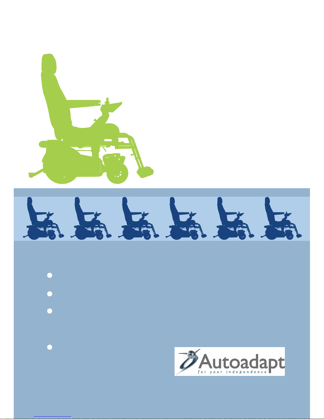
7
0:1 Technical data
General
Seat angle 17º
Depth of seat 493 mm
Seat width 408 mm
Height of seat surface in front 510 mm
Backrest inclination -19º till 23º
Backrest height 653 mm
Backrest width 435 mm
Distance of headrest in front of backrest 34 mm
Height of backrest above seat 775 mm
BEV seat specifications
Total width, with air tyres 62 cm
Total width, puncture free wheels 60,9 cm
Length 75 cm
Length with anti-tip and foot rests 108 cm
Height without seat 38 cm
Height with seat 115 cm
Total weight 93 kg
Weight of wheel unit with batteries 75 kg
Clearence beneath wheelchair 65 mm
Adjustable seat height 42-55 cm
Dimension front wheels 200x50 mm
Tyre pressure front wheels 2,6 bar
Dimension rear wheels 315x50 mm
Tyre pressure rear wheels 2,8 bar
Range 25 km
Max speed 6,5 km/h
Max reverse speed 3 km/h
Braking distance 0,8 m
Obstacle clearence 6 cm
Turning space180 degrees 150 cm
Hill-climbing ability 6 grader
Max user weight 120 kg
Battery type AGM; 1245
Batteriy max dimension 198x 165x170
Main fuse 50 A
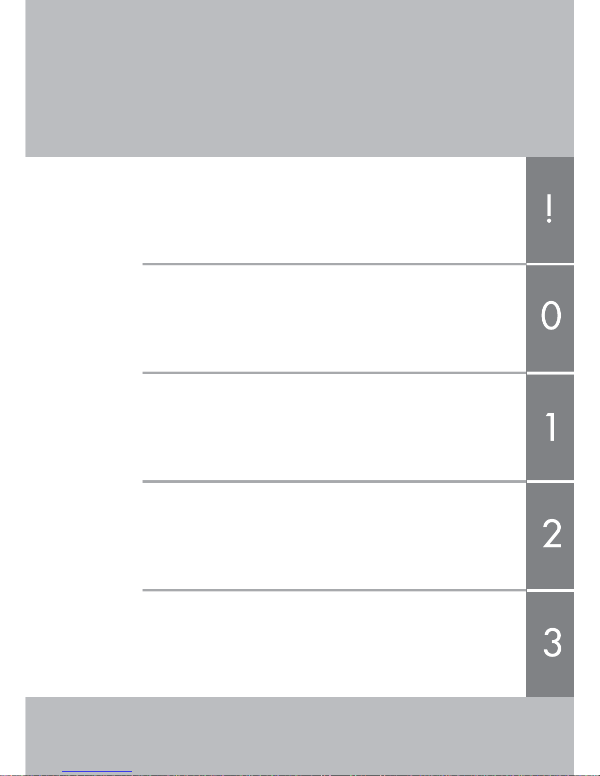
Carony Go/ Drive
Go: Drive:
110-122 cm
33,5 cm
112-126 cm
110 kg
92 kg
65 mm (35 mm)
37-51 cm
Distance from footplate to seat 404-550 mm in 8 steps
Length of footplate 129 mm
Footplate angle variable
Angle of legrest to seat surface 104º
Armrest height 285 mm
Distance to backrest from front edge
of armrest 335 mm
Armrest length 356 mm
Armrest width 57 mm
Armrest angle -38º to 10º
Distance between armrests 438 mm
Carony Go Carony Drive