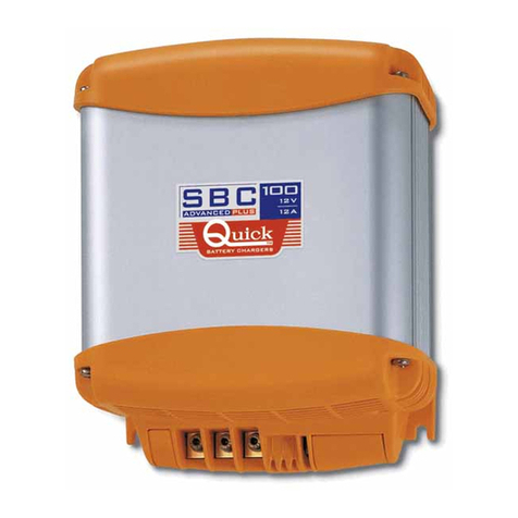
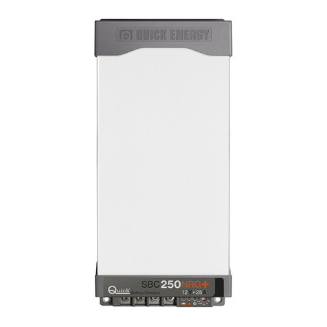
Quick SBC 1200 NRG+ FR User manual

CHARACTERISTICS AND INSTALLATION
EN
SBC NRG+ SERIES BATTERY CHARGER
The long experience we have in the nautical field has given us the ability to evolve the range of SBC battery chargers, now
called NRG+, with superior performance to those currently on the market.
The advantages which the SBC NRG+ battery chargers offer, are:
• Three stage IUoU battery charging.
• High efficiency.
•
Multiple outputs in order to charge more groups of batteries (MOSFET charge separator inside).
• Differentiated charging for open or sealed liquid electrolite, Gel, AGM, Optima
®
, Li-Ion batteries.
• Integrated output fuses inside the battery chargers (for each output).
• Thermal battery protection (with optional sensors).
• Capacity of supplying full power with low AC mains voltage.
• Possibility to connect in parallel up to three battery chargers of the same model for current sharing by means of digital
control.
• Low residual fluctuation on output.
• Universal AC supply input 264 ÷ 83 Vac, 45 ÷ 66 Hz (only models SBC 1100 NRG+ FR and SBC 1200 NRG+ FR).
• Power factor (cos
ϕ
) equal to 1.
• Compatible with the generators.
• Short circuit, overloading, output overvoltage and overheating protection.
• Can work in a wide range of ambient temperatures.
• Variable speed for the cooling fan.
• User interface via LEDs that signal the status, errors and the output current.
• Backlit LCD terminal with multi-language interface (optional).
• Charge is compensated according to the temperature of the batteries (1 sensor supplied; more sensors optional).
INSTALLATION
The installation of the battery charger must be carried out by qualied personnel.
BEFORE USING THE BATTERY CHARGER CAREFULLY READ THIS USER’S MANUAL. IF IN DOUBT,
CONTACT YOUR NEAREST DEALER OR “QUICK®” CUSTOMER SERVICE.
In case of discordance or errors in translation between the translated version and the original text in the Italian
language, reference will be made to the Italian or English text.
This device was designed and constructed for use on recreational crafts.
Other forms of use are not permitted without written authorization from the company Quick
®
.
THE BATTERY CHARGERS ARE DESIGNED FOR FIXED INTERNAL INSTALLATIONS ONLY.
WARNING:
this appliance is not intended for use by persons (including children) with reduced physical, sensory
or mental capabilities, or lack of experience and knowledge, unless they have been given supervision or instruction
concerning use of the appliance by a person responsible for their safety.
WARNING:
children should be supervised to ensure that they do not play with the appliance.
“Quick
®
” battery chargers have been designed and made for the reasons described in this user’s manual. The “Quick
®
”
Company does not accept any responsibility for direct or indirect damage caused by improper use of the equipment, bad
installation or by possible errors occurring in this manual.
OPENING OF THE BATTERY CHARGER BY UNAUTHORISED PERSONNEL MAKES THE WARRANTY VOID.
THE PACKAGE CONTAINS:
battery charger - conditions of warranty - user’s manual - connector (to connect to the
output terminals) - charge compensation sensor.
F
F
EN
INSTALLATION
INSTALLATION SITE
Install the battery charger as close as possible to the batteries in a dry and airy
spot, to allow the correct operation of the device at full power.
The battery charger can be installed on a horizontal surface or vertical wall paying
attention that the output connector faces downwards.
In case of battery chargers connected in parallel (current sharing mode), install-
ing one next to the other.
The battery charger must be fixed to the support surface with screws strong
enough to support its weight, paying attention that they do not weaken or cause
cracks tothe boat structure.
Vertical installation is recommended since the natural convection of the heat will
favour the cooling of the device.
The perimeter of the battery charger (excluding the support base) must be kept at
a distance from walls or objects by a minimum of 5 cm.
WARNING:
the battery charger must be used only with re-chargeable lead/liquid electrolytic batteries (open or
sealed), Gel, AGM, Optima
®
, Li-Ion.
WARNING:
the battery charger can not be used to recharge non rechargeable batteries.
NECESSARY EQUIPMENT FOR INSTALLATION
Depending upon model, use the batteries and cables on the output terminals as specified in the following table:
MODEL SBC 1100 NRG+ FR SBC 1200 NRG+ FR SBC 1450 NRG+ HR SBC 1950 NRG+ HR SBC 2450 NRG+ HR
Battery voltage 12 V 24 V
Battery capacity 360 ÷ 600 Ah 450 ÷ 1000 Ah 270 ÷ 600 Ah 360 ÷ 800 Ah 450 ÷ 1000 Ah
Minimum output cable size 25 mm235 mm225 mm235 mm235 mm2
Number of battery cells 6 12
MODEL SBC 1100 NRG+ FR
2 units in parallel
SBC 1200 NRG+ HR
2 units in parallel
SBC 1450 NRG+ HR
2 units in parallel
SBC 1950 NRG+ HR
2 units in parallel
SBC 2450 NRG+ HR
2 units in parallel
Battery voltage 12 V 24 V
Battery capacity 720 ÷ 1200 Ah 900 ÷ 2000 Ah 540 ÷ 1200 Ah 720 ÷ 1600 Ah 900 ÷ 2000 Ah
Minimum output cable size
(battery charger-junction “J”) 25 mm235 mm225 mm235 mm235 mm2
Minimum output cable size
(junction “J” - battery) 50 mm295 mm250 mm270 mm295 mm2
Number of battery cells 6 12
MODEL SBC 1100 NRG+ FR
3 units in parallel
SBC 1200 NRG+ HR
3 units in parallel
SBC 1450 NRG+ HR
3 units in parallel
SBC 1950 NRG+ HR
3 units in parallel
SBC 2450 NRG+ HR
3 units in parallel
Battery voltage 12 V 24 V
Battery capacity 1080 ÷ 1800 Ah 1350 ÷ 3000 Ah 810 ÷ 1800 Ah 1080 ÷ 2400 Ah 1350 ÷ 3000 Ah
Minimum output cable size
(battery charger-junction “J”) 25 mm235 mm225 mm235 mm235 mm2
Minimum output cable size
(junction “J” - battery) 95 mm2150 mm295 mm2120 mm2150 mm2
Number of battery cells 6 12
For the single battery chargers, the wires connected to the output terminals must have a maximum length of 4 meters.
For the length of the output wires in case more battery chargers are connected in parallel (current sharing mode) refer to the diagram of Fig. 2B.
5 cm
5 cm
5 cm 5 cm
CONNECTOR

EN
INSTALLATION
EQUIPMENT SUPPLY
The equipment already includes a AC power cord. For connections to an AC mains see fig.1A.
Before powering up the battery charger check that the power supply voltage, described on the rating label (fig.1B), corre-
sponds to that supplied by the AC mains.
An overvoltage category III switch must be installed in the electrical circuit for the sole use of switching the equipment
ON/OFF.
The connections to the AC mains must be carried out according to local electrical codes.
WARNING:
before connecting or disconnecting the battery charger’s AC cord from the AC mains, please make sure
it is disconnected by bipolar switch.
Before connecting or disconnecting the DC wires from the battery charger’s output terminals, please ensure that the
device is disconnected by means of bipolar switch, from the AC mains and by means of a battery isolator from the
batteries.
WARNING:
in cases where the AC power cord could be damaged, have this changed by a “Quick
®
” service centre.
In order to avoid accidents, the equipment must only be opened by authorised personnel.
BLUE
YELLOW GREEN
BROWN
NEUTRAL
EARTH
LIVE
FIG.1A
BAT TERY
N° 3
BAT TERY
N° 2
BAT TERY
N° 1 BAT TERY
SWITCHES
FIG.1B
SBCXXXX NRG+ XXX XXV XXA XX XX
SN:XXXXXX Rev:XXX WY:XX/XX
INPUT:
~
XXXV,XXXV, 45-66Hz, X.XA MAX
OUTPUT: XXA MAXIMUM
ABSORPTION XX.XV OL XX.XV Li-Ion
XX.XV SL/GEL/AGM XX.XV Optima®
FLOAT XX.XV OL XXV Li-Ion XX.XV AGM
XX.XV SL/GEL/Optima®

EN
INSTALLATION
BATTERY SWITCHES
WARNING:
during charge, batteries can generate explosive gases, therefore avoid sparks or naked flames. Provide
adequate ventilation to the battery area whilst charging.
WARNING:
before connecting the batteries check the polarity of the cables from the battery. Reversing the polarity,
could seriously damage the battery charger even if protected by fuses.
FIG.2A
FIG.2B
L2
L1L3
J
L
BAT TERY
JM
JCN
JS1
JS2
J
S2
J
S1
J
M
J
CN
BAT TERY
N. 1
BAT TERY
N. 2
BAT TERY
N. 3
L1 = L2 = L3
shorter than 2 meters
L
shorter than 6 meters
This manual suits for next models
5
Table of contents
Other Quick Batteries Charger manuals

Quick
Quick SBC 300 ADV PLUS FR User manual

Quick
Quick SBC 100 ADV PLUS User manual

Quick
Quick SBC NRG Series Reference manual

Quick
Quick SBC 140 User manual

Quick
Quick SBC NRG+ Series Reference manual

Quick
Quick SBC 1100 NRG+ FR Reference manual

Quick
Quick SBC 140 NRG FR Reference manual

Quick
Quick SBC NRG+ Series Reference manual

Quick
Quick SBC NRG Series Reference manual

Quick
Quick SBC 100 ADV User manual