manuals.online logo
Brands
  1. Home
  2. •
  3. Brands
  4. •
  5. Autometers Systems
  6. •
  7. Measuring Instrument
  8. •
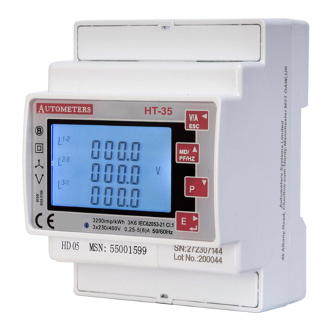
  9. Autometers Systems HORIZON HT-35 User manual

Autometers Systems HORIZON HT-35 User manual

Pulse Output
The pulse outputs can be set to generate pulses to
represent kWh/kVarh
Pulse constant: 0.001/0.01/0.1/1/10/100/1000 kWh or
kVarh per Pulse
Pulse width: 200/100/60 Ms.
The pulse output is passive type, complies with
IEC62053-31 Class A.
Uimp
R
OUTPUT
P+ Com
ATTENTION: Pulse output must be fed as shown in
the wiring diagram below. Scrupulously respect
polarties and the connection mode. Opto-coupler with
potential-free SPST-No Contact.
Contact range: 5~27VDC Max. current Input: 27mADC
Pulse
This option allows you to configure the pulse output. The output can be set to
provide a pulse for a defined amount of energy active or reactive.
This option sets the pulse output type, pulse rate, duration
time.
From the Set-up menu, Use and to select the
Pulse option.
Pulse rate
Pulse rate options: 0.001 , 0.01 , 0.1 , 1, 10, 100, 1000 kWh /
kVarh per Pulse. Default : 0.01 kWh (100imp/kWh)
Use and to select Pulse Rate option.
Long press the setting will flash.
Use and to choose Options.
Long press for confirmation.
Password Entry
Setting-up mode is password protected, so you must enter
the correct password.
By firmly pressing the button for 3 seconds, the
password screen appears.
The default password is 1000.
If an incorrect password is entered, the display shows ERR.
Programming the meter
When you receive the meter there will be at least one value that you must
programme into the meter. This is the current transformer ratio.
If the meter has been purchased with the intention of using the RS 485
Modbus output then you will have to program the Modbus parameters you
require. See reverse Communication. (RS 485 Modbus)
HT-35 METER
From the main Set-up menu, Use and to select the
CT option.
C.T. (Current Transformer)
C.T. Rate (Current Transformer)
To set the primary current ratio in the meter you must
program the divider into the meter. e.g. to set 200/5 amp
input “0040” (Divide the primary by 5) 5 amp being the
secondary of the c.t. See table below.
Options: 1~2000
Default CT rate 1. ( New Ratio Must Be Programmed Into
The Meter)
Long press to enter the CT Rate routine.
Press for 3s, the CT rate setting will flash.
Use and to choose CT rate with 1~2000.
And long press for confirmation
C.T.2 (Current Transformer)
Set C.T.2 secondary current input.
Options: 5A or 1A
Default CT2: 5A
Long press to enter the CT2 routine.
Press for 3s, the CT2 setting will flash.
Use and to choose CT2 with 5A or 1A.
Quick setup guide
MD/
PF/HZ
MD/
PF/HZ
P
MD/
PF/HZ
P
P
MD/
PF/HZ
P
MD/
PF/HZ
P
E
MD/
PF/HZ
P
E
E
E
MD/
PF/HZ
P
E
E
E
E
Example of meter set at 200/5 amp
Example of how
the display should
look for a meter
programmed to
200/5 amp.
See table for
more settings.
Number to program
into the meter
0020
0030
0040
0050
0060
0080
0100
0120
0160
C.T Primary
100/5
150/5
200/5
250/5
300/5
400/5
500/5
600/5
800/5
C.T Primary
100/1
150/1
200/1
250/1
300/1
400/1
500/1
600/1
800/1
Number to program
into the meter
0100
0150
0200
0250
0300
0400
0500
0600
0800
Example of meter set at 200/1 amp
Example of how
the display should
look for a meter
programmed to
200/1 amp.
See table for
more settings.
To check the settings which have been progammed into the
meter.
Long press Modbus Address.
Short press to scroll through the other settings:
Baud Rate
Parity
Primary current transformer ratio ( c. .t 1)
Secondary current transformer ratio ( c.t. 2)
Meter serial number, 7 day program time
Date and Time
Tariff 1-8
Full test icons on display
IMPORTANT NOTICE
The HT-35 is a MID approved panel meter, once you have altered any of the
parameters e.g. Current transformer ratio or voltage ratio and you have come
out of the programming mode you cannot alter them again.
This rule does not apply to the Modbus settings.
Meter programming check
Pulse Duration time option 200, 100, 60mS
Default : 100mS
Use and to enter Pulse duration routine.
Long press , the setting will flash. Use and to
choose Options.
And long press for confirmation.
Press to return the Pulse Duration set up menu.
Pulse Duration
Baud rate
Baud rate options: 2400 4800 9600 19200 38400 (bps).
Default: 9600bps
From the Set-up menu, Use and to select the Baud
rate options.
Long press to enter the selection routine.
The Baud Rate setting will flash. Use and to choose
Baud Rate.
And long press for confirmation
Parity
Parity Options: NONE, EVEN, ODD.
Default Parity : EVEN
Note that if parity is set to ODD or EVEN, Stop Bits will be set
to 1 and cannot be changed.
From the Set-up menu, Use and to select the
Parity options.
Long Press to enter the selection routine.
The Parity setting will flash. Use and to choose
Parity.
Example shows:
Set Parity: EVEN
And long press for confirmation.
Press to return the main set up menu.
Address
An RS485 network can accommodate up to 255 different
devices, each identified by an individual address.
The Modbus address range on the HT-35 is between
001~247
Default setting from Autometers is 001
Long press to enter the selection routine.
The address setting will flash. Use and to
increment or reduce the number.
Long press for confirmation.
Product development is continuous and Autometers Systems Limited reserves the
right to make alterations and manufacture without notice. Products as delivered may
therefor differ from the descriptions and illustrations in this publication
Autometers Systems Ltd.
4B Albany Road, Chorlton-cum-Hardy
Manchester M21 0AW
Email: [email protected]
Phone: 00(44) 0161 861 9056
www.autometers.co.uk
Communication (RS 485 Modbus)
The RS485 port can be used for communications using
Modbus RTU protocol. Parameters such as Address, Baud
rate, Parity, Stop bit can be selected.
Long press to enter the Address option.
Communication status
Indication only
Electrician
The HT-35 DIN rail meter should only be installed by a fully qualified electrician who
has knowledge of electricity meters connected with current transformers.
It is the installer who is fully responsible for the safe installation of this meter. It must
be installed to meet the current electrical regulations concerning installation of
electricity meters.
EMC Installation Requirements
Please see full installation brochure for details - visit autometers.co.uk
Wiring Information
Power Supply
The HT-35 receives it power from any one of the voltage connections and Neutral.
Wiring
All electrical and comunication cables to be connected as per the daigaram shown on
the leaflet.
All terminals are green in colour and can be unplugged, The current terminals are
screwed in but can be unplugged if the screws are removed
Electrical Connections
Autometers recommend that all cables from the current transformers are 2.5 multi
stranded flexible cables and do not exceed 2 metres. For longer distances please
contact Autometers for advice.
The comunication cable must be a twisted pair shielded like belden 9841 or 9842.
Phasing and polarity of the AC current and voltage inputs and their relationship is
critical to the correct operation.
Dimensions
Dimensions are 72mm width x 94.5mm height x 65mm deep
The cut out hole for the panel meter is 73mm x 46mm
For full installation brochure please visit autometers.co.uk
Wiring Diagram for 3 phase 4 wire
V/A
ESC
V/A
ESC
E
E
E
E
MD/
PF/HZ
P
MD/
PF/HZ
P
E
E
E
MD/
PF/HZ
P
MD/
PF/HZ
P
MD/
PF/HZ
P
E
E
MD/
PF/HZ
P
MD/
PF/HZ
P
P2
S1
S2
P2
S1
S2
P2
S1
S2
LOAD
MAINS
LOAD
TX-TX+1 2
+ - +
1A FAST BLOW FUSE 1A FAST BLOW FUSE
AUX
L1
L2
L3
N
L1
L2
L3
SHIELD
S0 RS 485 Current inputs
9 10 11 12 13 14 15 16 17 18 19 20
1 2 3 4 5 6 7 8
Voltage inputs L N L N
Pulse Modbus L3 L2 L1
S2 S1 S2 S2 S1S1
IMPORTANT
Current transformer
P1 must face mains
LOAD
MAINS
S2 S1
P2
Ref.HT-35.04.2022
Terminals 5 & 6
(auxiliary supplies)
must be connected

Other manuals for HORIZON HT-35

1

Other Autometers Systems Measuring Instrument manuals

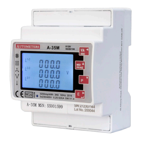
Autometers Systems A-35M User manual

Autometers Systems

Autometers Systems A-35M User manual

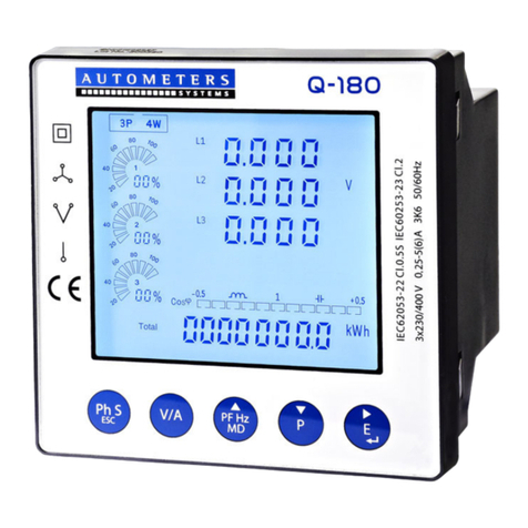
Autometers Systems Q-180 User manual

Autometers Systems

Autometers Systems Q-180 User manual

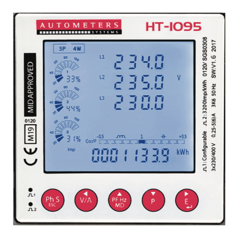
Autometers Systems HORIZON HT-1095 User manual

Autometers Systems

Autometers Systems HORIZON HT-1095 User manual

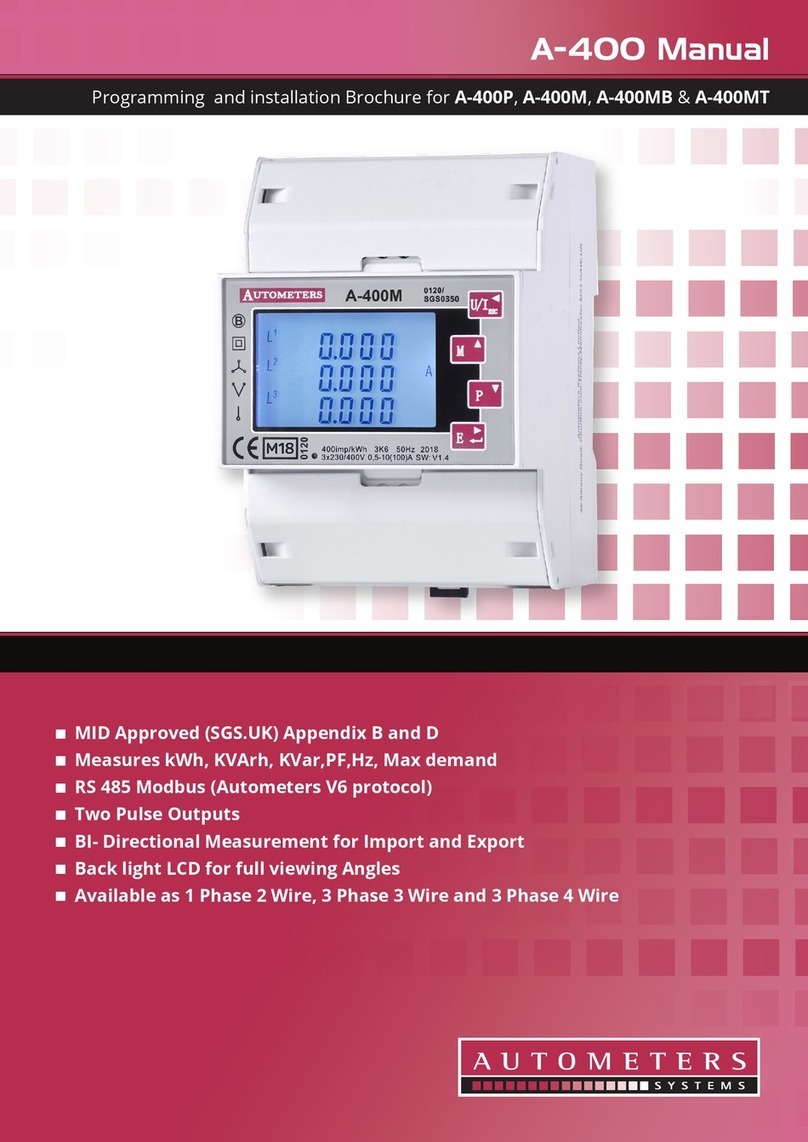
Autometers Systems A-400 Series User manual

Autometers Systems

Autometers Systems A-400 Series User manual

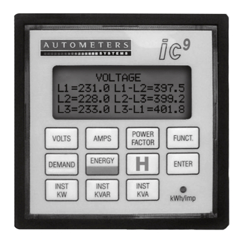
Autometers Systems ic9 User manual

Autometers Systems

Autometers Systems ic9 User manual

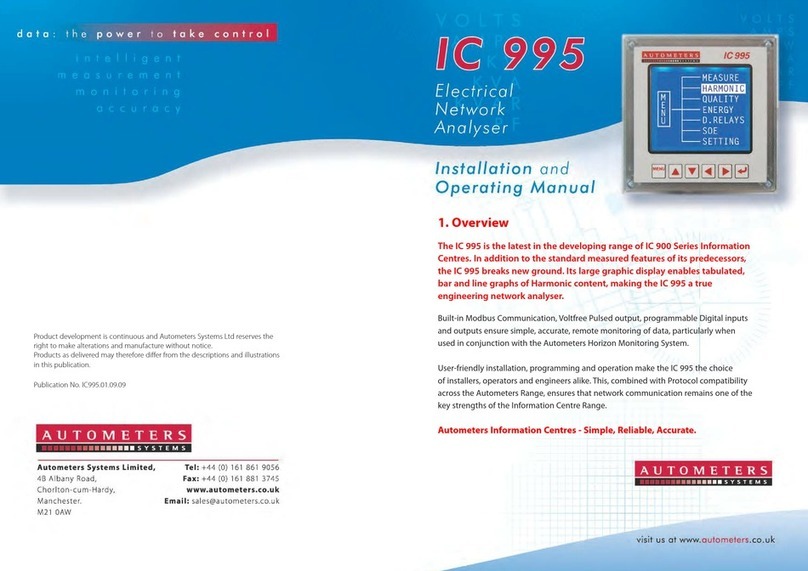
Autometers Systems IC 995 User manual

Autometers Systems

Autometers Systems IC 995 User manual

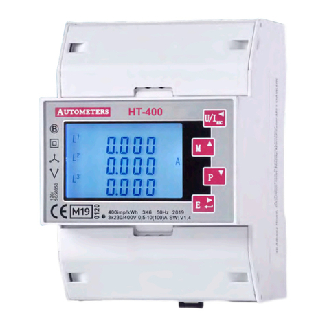
Autometers Systems HORIZON HT-400 User manual

Autometers Systems

Autometers Systems HORIZON HT-400 User manual

Autometers Systems HORIZON HT-35 User manual

Autometers Systems

Autometers Systems HORIZON HT-35 User manual

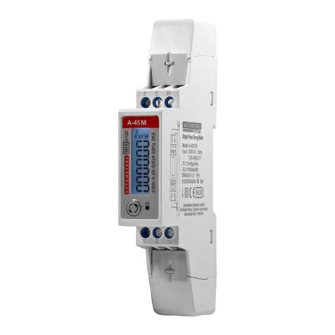
Autometers Systems A-45 Series User manual

Autometers Systems

Autometers Systems A-45 Series User manual

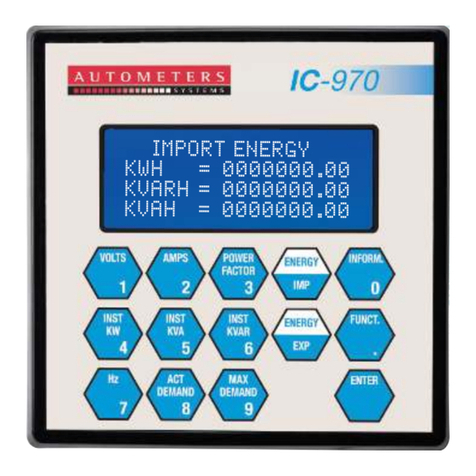
Autometers Systems IC 970 Installation instructions

Autometers Systems

Autometers Systems IC 970 Installation instructions

Autometers Systems HORIZON HT-1095 User manual

Autometers Systems

Autometers Systems HORIZON HT-1095 User manual

Autometers Systems ADP3-80C User manual

Autometers Systems

Autometers Systems ADP3-80C User manual

Popular Measuring Instrument manuals by other brands

Takachiho Sangyo GUIDER 6 PLUS Operation manual

Takachiho Sangyo

Takachiho Sangyo GUIDER 6 PLUS Operation manual

LINSHANG LS132 user manual

LINSHANG

LINSHANG LS132 user manual

TSI Instruments VelociCalc 9515-AC Operation and service manual

TSI Instruments

TSI Instruments VelociCalc 9515-AC Operation and service manual

Dwyer Instruments 471B Specification and operating instructions

Dwyer Instruments

Dwyer Instruments 471B Specification and operating instructions

Seitron PRESSOTEST 200 manual

Seitron

Seitron PRESSOTEST 200 manual

NIEUWKOOP RE1500 user manual

NIEUWKOOP

NIEUWKOOP RE1500 user manual

Lutron Electronics FG-6020SD Operation manual

Lutron Electronics

Lutron Electronics FG-6020SD Operation manual

pico Technology TA133 user manual

pico Technology

pico Technology TA133 user manual

Siemens sitrans PROBE LU Quick start manual

Siemens

Siemens sitrans PROBE LU Quick start manual

Gas Clip MGC Pump user manual

Gas Clip

Gas Clip MGC Pump user manual

Endress+Hauser Deltabar PMD55B operating instructions

Endress+Hauser

Endress+Hauser Deltabar PMD55B operating instructions

OWL +USB user manual

OWL

OWL +USB user manual

Shimpo Instruments FG-7000 Operation manual

Shimpo Instruments

Shimpo Instruments FG-7000 Operation manual

ICD MFM 9012 operating manual

ICD

ICD MFM 9012 operating manual

Bierer HP72 operating instructions

Bierer

Bierer HP72 operating instructions

Nidec-Shimpo FGE-0.5XY Operation guide

Nidec-Shimpo

Nidec-Shimpo FGE-0.5XY Operation guide

3M WIBGET WB-300 user manual

3M

3M WIBGET WB-300 user manual

Nibe EMK 300 Installer manual

Nibe

Nibe EMK 300 Installer manual

manuals.online logo
manuals.online logoBrands
  • About & Mission
  • Contact us
  • Privacy Policy
  • Terms and Conditions

Copyright 2025 Manuals.Online. All Rights Reserved.