Autometers Systems HORIZON HT-1095 User manual

HORIZON SYSTEM METER HT-1095
Multi Function , Multi Tariff , MID Approved. Autometers Modbus V6.
Energy Monitoring and Invoicing

Contents
www.autometers.co.uk
Introduction
1. Unit characteristics
1.1 Measuring and display
1.2 Password protection
1.3 CT and PT
1.4 RS485 Serial Modbus RTU
1.5 Pulse output
2. Start up screens
3. Keys and displays
3.1 Button functions
3.2 Display mode screen sequence
3.3 Individual harmonic distortion
4. Display information
5. programming the meter
5.1 Password entry
5.2 Communication
5.2.1 Address
5.2.2 Baud rate
5.2.3 Parity
5.3 C.T. (Current Transformer)
5.3.1 C.T.2 (Current Transformer)
5.3.2 C.T. rate (Current Transformer)
5.3.3 Example of a meter set at 200/5amp
5.4 P.T. (Voltage Supply)
5.4.1 P.T.2 (Voltage Supply)
5.4.2 P.T.1 rate (Primary Voltage)
5.5 Pulse
5.5.1 Pulse output 1
5.5.2 Pulse rate
5.5.3 Pulse duration
5.6 Demand
5.6.1 Demand interval time
5.6.2 Demand method
5.7 Back light display time setting
5.7.1 Backlight time
5.7.2 Display scroll time
5.7.3 Set system RTC & time
5.7.4 Set tariff
5.8 System (network connection)
5.8.1 System network
5.8.2 System connect (C.T correction)
5.8.3 Change password
5.8.4 Automatic display control
5.9 Parameter reset
6. Specification
6.1 Measured parameters
6.1.1 Voltage and current
6.1.2 Power factor and frequency maximum demand
6.1.3 Energy measurements
6.1.4 Accuracy
6.1.5 Display
6.1.6 Pulse output
6.1.7 Modbus RTU
6.1.8 Dimensions and material
6.2 Environment
7. Maintenance
8. Installation
8.1 Safety
9. Electrician
10. EMC requirements
11. Dimensions
12. Wiring diagram
13. Metal enclosures for the HT-1095
14. Sealing points
15. The Horizon Energy Monitoring System with the HT-1095
1
2
2
2
2
2
2
3
3
3
4
6
7
8
9
9
9
10
10
10
10
10
11
11
11
11
12
12
12
13
13
13
13
14
14
14
14
15
15
16
16
17
17
18
19
19
19
19
19
19
19
20
20
20
20
21
21
21
21
21
22
23
24
24
25
..............................................................................................................................
.............................................................................................................
..............................................................................................
.................................................................................................
....................................................................................................................
.........................................................................................
...............................................................................................................
...................................................................................................................
................................................................................................................
........................................................................................................
...............................................................................
................................................................................
.............................................................................................................
.....................................................................................................
...........................................................................................................
..........................................................................................................
............................................................................................................
..........................................................................................................
.................................................................................................................
.......................................................................................
..........................................................................
....................................................................
...........................................................
..................................................................................................
.....................................................................................
...........................................................................
............................................................................................................................
..................................................................................................
.........................................................................................................
.................................................................................................
.......................................................................................................................
.....................................................................................
.............................................................................................
..................................................................................
..................................................................................................
...........................................................................................
....................................................................................
............................................................................................................
...................................................................................
...............................................................................................
....................................................................
............................................................................................
..............................................................................
.........................................................................................................
..........................................................................................................................
...............................................................................................
........................................................................................
........................................
...................................................................................
...........................................................................................................
..............................................................................................................
.....................................................................................................
.....................................................................................................
...............................................................................
...............................................................................................................
.........................................................................................................................
............................................................................................................................
...........................................................................................................................
.............................................................................................................................
.............................................................................................................
........................................................................................................................
..................................................................................................................
....................................................................................
.....................................................................................................................
..........................................

Introduction
The HT-1095 is a multifunction energy
analyzer and is the latest in a new
generation of MID approved intelligent
panel meters used not only in the
electricity transmission and power
distribution system, but also in the
power consumption measurement and
analysis in high voltage intelligent power
grid.
The HT-1095 is capable of measuring
electricity in one phase two wire, three
phase three wire or three phase four
wire electrical systems.
The meter is a 96 x 96mm panel
mounted meter designed to be easy to
use and easy to read, the meter comes
with five control buttons for scrolling
and programming with a large back light
display for ease of reading. See picture
opposite.
The meter displays the following
information: Voltage, Frequency,
Current, Power active and reactive
energy, imported or exported, Power
factor, Max. Demand and Harmonics
distortion measurement on current and
voltage to the 63rd.
Energy is measured in terms of kWh,
kVArh. Maximum demand current can
be measured over preset periods of up
to 60minutes. In order to measure
energy the unit requires voltage and
current inputs.
The HT-1095 is a 1 amp or 5 amp current
operating measuring device and can
only work with current transformers.
Due to the design of the HT-1095 it is
fully programmable via the front keys to
enable a wide range of settings to match
any current transformer manufactured.
The Information Centre can be supplied
with a pulse Output or Autometers RS
485 Modbus protocol v.6.
Configuration is password protected.
This document provides operating,
maintenance and installation
instructions for the Autometers HT-1095.
www.autometers.co.uk 1

1. Unit Characteristics
1. 1 The Unit can measure and display:
Line voltage and THD% (total harmonic distortion) of all phases
2~63rd voltage IHD% (Individual Harmonic distortion) of all phases
Line Frequency
Currents, Current demands and current THD% of all phases
2~63rd current IHD% of all phases
Active power, reactive power, apparent power, maximum power demand and power factor
Active energy imported and exported
Reactive energy imported and exported
Energy of each phase
IMPORTANT NOTICE
The HT-1095 is a MID approved panel meter, once you have altered any of the parameters
e.g. Current transformer ratio or voltage ratio and you have come out of the programming
mode you cannot alter them again.
This rule does not apply to the Modbus settings.
1.2 The unit has password-protected set-up screens for:
Communication setting: Modbus address, Baud rate, Parity, Stop bit
CT setting: CT ( Primary) , CT2 ( Secondary), CT rate
PT setting: PT (Primary), PT2 (Secondary) , PT rate
Pulse setting: Pulse output 1, Pulse rate, Pulse time
Demand setting: Demand interval time, demand method
Time setting: Backlit time, display scroll time
Multiple tariff settings
System configuration: System type, System connect, Change password, Auto display scroll
Reset
1.3 CT and PT
CT (primary current) 1~2000A
CT2 (secondary current): 1A or 5A
PT (primary voltage): 1~2000V
PT2 (secondary voltage): 100 to 480 V AC (L-L)
1.4 RS485 Serial-Modbus RTU
This unit uses a RS485 serial port with Modbus RTU protocol to provide a means of remote
monitoring and controlling. Please check section 5.2 for the details of setting.
1.5 Pulse output
Two pulse outputs indicate real-time energy measurement. Pulse output 1 is configurable, pulse
output 2 is fixed to active energy, 3200imp/kWh.
www.autometers.co.uk2

The first screen
lights all LED
segments and can
be used as a
display LED check
The second screen
indicates the
software version of
the unit.
(the above picture is
just for reference)
The unit performs a
self-test and the
screen indicates if
the test is passed.
After a short delay,
the default
measurement
screen appears.
3. Keys and Displays
3.1 Button Functions
Click
Display power, voltage, current and
energy information of each phase
Escape the menu
Display voltage and current
information of the selected system
type. (3p4w, 3p3w and 1p2w)
Left side move
Display power factor, frequency,
Max. Demand. Maximum and
Minimum value.
Up page or add value
Display active power, reactive power
and apparent power information of
the selected system type.
Down page or reduce value
Display import / export active or
reactive energy information of the
selected system type.
Right side move
Press and hold down for 3 seconds
Automatic Scroll display ON / OFF
Individual Harmonic Distortion of
Voltage up to 63rd
Individual Harmonic Distortion of
Current up to 63rd
Modbus ID
Baud rate
Parity
Identification code
Running hours
Full screen
Set-up mode entry
Confirmation
Button
2.Start up screens
Ph S
ESC
P
V/A
PF Hz
MD
E
www.autometers.co.uk 3

Ph S
ESC
Click button 3 Phase 4 Wire 3 Phase 3 Wire 1 Phase 2 Wire
Screen Parameters Screen Parameters Screen Parameters
1Phase 1 – Power
Voltage
Current
kWh
1Phase 1 – Power
Current
kWh
1Phase 1 – Power
Voltage
Current
kWh
2 Phase 2 – Power
Voltage
Current
kWh
2 Phase 2 – Power
Current
kWh
3 Phase 3 – Power
Voltage
Current
kWh
3 Phase 3 – Power
Current
kWh
4 Phase 1 – Power
Voltage
Current
kVarh
4 Phase 1 – Power
Current
kVarh
2 Phase 1 – Power
Voltage
Current
kVarh
5 Phase 2 – Power
Voltage
Current
kVarh
5 Phase 2 – Power
Current
kVarh
6 Phase 3 – Power
Voltage
Current
kVarh
6 Phase 3 – Power
Current
kVarh
1Voltage L1-N
Voltage L2-N
Voltage L3-N
1Voltage L1-N
2 Voltage L1-L2
Voltage L2-L3
Voltage L3-L1
1Voltage L1-L2
Voltage L2-L3
Voltage L3-L1
3 Current L1
Current L2
Current L3
Current Neutral
2 Current L1
Current L2
Current L3
2 Current L1
4 THD% of Voltage L1
THD% of Voltage L2
THD% of Voltage L3
3 THD% of Voltage L1-2
THD% of Voltage L2-3
THD% of Voltage L3-1
3 THD% of Voltage L1
5 THD% of Current L1
THD% of Current L2
THD% of Current L3
4 THD% of Current L1
THD% of Current L2
THD% of Current L3
4 THD% of Current L1
6 Phase Sequence 5 Phase Sequence
V/A
3.2 Display Mode Screen Sequence
www.autometers.co.uk4

Click button 3 Phase 4 Wire 3 Phase 3 Wire 1 Phase 2 Wire
Screen Parameters Screen Parameters Screen Parameters
1Total Power Factor
Frequency
1Total Power Factor
Frequency
1Total Power Factor
Frequency
2 PF L1
PF L2
PF L3
2 PF L1
PF L2
PF L3
3 Max. DMD of Current L1
Max. DMD of Current L2
Max. DMD of Current L3
3 Max. DMD of Current L1
Max. DMD of Current L2
Max. DMD of Current L3
2 Max. DMD of Current L1
4 Max. DMD of W
Max. DMD of Var
Max. DMD of VA
4 Max. DMD of W
Max. DMD of Var
Max. DMD of VA
3 L1 Max. DMD of W
L1 Max. DMD of Var
L1 Max. DMD of VA
5 Max. Voltage of L1
Max. Voltage of L2
Max. Voltage of L3
5 Max. Voltage of L1-2
Max. Voltage of L2-3
Max. Voltage of L3-1
4 Max. Voltage of L1
6 Min. Voltage of L1
Min. Voltage of L2
Min. Voltage of L3
6 Min. Voltage of L1-2
Min. Voltage of L2-3
Min. Voltage of L3-1
5 Min. Voltage of L1
7 Max. Current of L1
Max. Current of L2
Max. Current of L3
Max. Current of N
7 Max. Current of L1
Max. Current of L2
Max. Current of L3
Max. Current of N
6 Max. Current of L1
8 Min. Current of L1
Min. Current of L2
Min. Current of L3
Min. Current of N
8 Min. Current of L1
Min. Current of L2
Min. Current of L3
Min. Current of N
7. Min. Current of L1
1Active Power L1
Active Power L2
Active Power L3
1Active Power L1
Active Power L2
Active Power L3
2 Reactive Power L1
Reactive Power L2
Reactive Power L3
2 Reactive Power L1
Reactive Power L2
Reactive Power L3
3 Apparent Power L1
Apparent Power L2
Apparent Power L3
3 Apparent Power L1
Apparent Power L2
Apparent Power L3
4 Total Active Power
Total Reactive Power
Total Apparent Power
4 Total Active Power
Total Reactive Power
Total Apparent Power
1L1 Active Power
L1 Reactive Power
L1 Apparent Power
P
PF Hz
MD
www.autometers.co.uk 5

Click button 3 Phase 4 Wire 3 Phase 3 Wire 1 Phase 2 Wire
Screen Parameters Screen Parameters Screen Parameters
1 1 1
2 2 2
3
Import kWh
3
Import kWh
3
Import kWh
4
Export kWh
4
Export kWh
4
Export kWh
5
Import kVarh
5
Import kVarh
5
Import kVarh
6
Export KVarh
6
Export KVarh
6
Export KVarh
E
7
T1 import kWh
7
T1 import kWh
7
T1 import kWh
8
T2 import kWh
8
T2 import kWh
8
T2 import kWh
9
T3 import kWh
9
T3 import kWh
9
T3 import kWh
10
T4 import kWh
10
T4 import kWh
10
T4 import kWh
Date Date Date
Time Time Time
Press the button for 3 seconds to check Harmonic distortion of
voltage
2~63rd Harmonic distortion of voltage
Press the button for 3 seconds to check Harmonic
distortion of current
2~63rd Harmonic distortion of current
3.3 Individual Harmonic Distortion:
PF Hz
MD
www.autometers.co.uk
6
V/A

4. Display information
Phone symbol on when
communicating (Modbus)
Pulse OutputsDescription on energy
being monitored.
Individual phases and
Neutral.
Network system
programmed into the
meter
Circular graph indicating
percentage of load
flowing on each phase.
Clock indicates tariffs.
Numbers 1-4 indicate
tariff numbers available.
Man running indicates
the actual tariff running.
Total Import and Export
Energy registers.
( 8 digits.)
Overload warning Indicator
flashes when any of the phases
have reached 120 % of primary
current transformer setting
Energy Register (8 digit)
Description of energy
reading. (kWh and kVArh)
Power Factor bar graph.
Description of
instantaneous Energy,
Pf, Hz and Harmonics
readings per phase.
Pulse output indicator
lights
Circular touch activation
keys (5)
Import or Export icons
per phase and Neutral
www.autometers.co.uk 7

PASSWOrd (Change Password)
dIt (Demand Interval Time)
CT2
Select from:
60 minutes
30 minutes
15 minutes
10 minutes
8 minutes
5 minutes
OFF
1~2000
dMd (Demand)
Select from:
Select from:
Select from:
Select from:
Select from:
Select from:
Select from:
Select from: (bps)
SyS COCt (system connect)
AUtO Ld SCrISP ON
OFF
Select from:
Select from:
Select from:
Select from:
Select from:
Select from:
Select from:
Select from:
120 minutes
60 minutes
30 minutes
10 minutes
5 minutes
ON
OFF
1~9999
1~2000
5. Programming the meter
sliding
fixed
dISP SCrL (display scroll)
SYS RTC (real time clock)
TRFF TIME (tariff/time segment)
SyS tyPE (system type)
1~255s
Date: YYYY-MM-DD
Time: HH-MM-SS
4 tariff and 8 time segments
3P4
3P3
1P2
Ph-1 (phase1)
Ph-2 (phase 2)
Ph-3 (phase3)
Frd/rEv (forward / reverse)
Frd/rEv (forward / reverse)
Frd/rEv (forward / reverse)
Entry Pasword Between:
0000~9999
SyS COCt (system connect)
PASSWOrd (change password)
AUTO dISP SCrL
ALL
EnGY
dMd
rSET (Reset)
SyS (System Configuration)
bACk LIt (backlight)
100 mS
200 mS
60 mS
PULS tIME
PULS RAtE 0.001
0.01
0.1
1
10
100
1000 KWh(kVArh)/imp
tIME (Time)
PULS (Pulse) PULS OUt 1 Total kWh
Total kVarh
ImpkWh
Exp kWh
Imp kVarh
Exp kVarh
PT (System Configuration) PT2
PT rAtE Entry PT Ratio Value between:
Entry Secondary Voltage between:
CT1 (When CT2=0.1A/0.333V
100~500
Entry CT1 Value between:
Entry CT Ratio Value between:
5A
1A
CT rAtE (when CT2=5A/1A)
CT (System Configuration)
PArI (parity) NONE
EVEN
Odd
2400
4800
9600
19.2k
38.4k
bAUd (Baud rate)
Entry Value between:
1~247
Addr (Address)COMS (Communication)Password EntryMain screen
dMd MEth (Demand Method)
www.autometers.co.uk8

5.1 Password Entry
Setting-up mode is password protected, so you must enter the correct
password.
By firmly pressing the button for 3 seconds, the password screen
appears.
The default password is 1000.
If an incorrect password is entered, the display shows ERR.
5.2 Communication
The RS485 port can be used for communications using Modbus RTU
protocol. Parameters such as Address, Baud rate and Parity can be
selected.
Long press to enter the Address option.
5.2.1 Address
An RS485 network can accommodate up to 247 different devices, each
identified by an individual address.
The Modbus address range on the HT-1095 is between 001~247
Default setting from Autometers is 001
Long press to enter the selection routine.
The address setting will flash. Use and to increment or reduce
the number.
Long press for confirmation.
5.2.2 Baud rate
Baud rate options: 1200 2400 4800 9600 19200 38400 (bps).
Default: 9600bps
From the Set-up menu, Use and to select the Baud rate options.
Long press to enter the selection routine.
The Baud Rate setting will flash. Use and to choose Baud Rate.
And long press for confirmation
P
PF Hz
MD
P
PF Hz
MD
P
PF Hz
MD
E
E
E
E
E
E
www.autometers.co.uk 9

5.2.3 Parity
Parity Options: NONE, EVEN, ODD.
Default Parity : EVEN
From the Set-up menu, Use and to select the Parity options.
Long Press to enter the selection routine.
The Parity setting will flash. Use and to choose Parity.
Example shows:
Set Parity: EVEN
And long press for confirmation.
Press to return the main set up menu.
From the main Set-up menu, Use and to select the CT option.
5.3 C.T. (Current Transformer)
Set C.T.2 secondary current input.
Options: 5A or 1A
Default CT2: 5A
Long press to enter the CT2 routine.
Long press , the CT2 setting will flash.
Use and to choose CT2 with 5A or 1A.
5.3.2 C.T. Rate (Current Transformer)
To set the primary current ratio in the meter you must program the divider
into the meter. e.g. to set 200/5 amp input “0040” (Divide the primary by 5)
5 amp being the secondary of the c.t. see section 5.3.3 for the table.
Options: 1~2000
Default CT rate 1. ( New Ratio Must Be Programmed Into The Meter)
Long press to enter the CT Rate routine.
long press , the CT rate setting will flash.
Use and to choose CT rate with 1~2000.
And long press for confirmation
5.3.1 C.T.2 (Current Transformer)
Ph S
ESC
P
PF Hz
MD
P
PF Hz
MD
P
PF Hz
MD
P
PF Hz
MD
E
E
P
PF Hz
MD
E
E
E
E
E
www.autometers.co.uk
10

5.3.3. Example of meter set at 200/5 amp
Example of how the display should look for a meter programmed to 200/5 amp.
See table for more settings.
5.4 P.T. (Voltage Supply)
The meter has been designed to work in 3 phase 4 wire or a 3 phase 3 wire
network and this requires a primary and secondary voltage ratio input.
The default is a 3 phase 4 wire configuration.
Long press to enter the PT2 routine.
For example:
A 3 phase 3 wire, 11000/110 Volt configuration:
Set the secondary (P.T.2) to 110 and the “RATE” (P.T.1 multiplier) to 100.
(110 X100 = 11,000)
5.4.1 P.T.2 (voltage supply)
Set secondary voltage input the meter
Range: 100V ~ 480V
Default: 230V ( L-N)
Long press for confirmation.
5.4.2 P.T.1 (Primary Voltage)
Set primary voltage input the meter
Range: 1V ~ 2000V
Default: 1
Then press to enter the PT1 routine.
Long press , the PT1 setting will flash.
Use or , to select PT1.
Long press for confirmation.
Press to return the PT set up menu.
C.T Primary
100/5
150/5
200/5
250/5
300/5
400/5
500/5
600/5
Number to program into
the meter
20
30
40
50
60
80
100
120
C.T Primary
800/5
1000/5
1200/5
1500/5
1600/5
2000/5
2500/5
3000/5
Number to program into
the meter
160
200
240
300
320
400
500
600
Ph S
ESC
P
P
E
E
E
E
E
www.autometers.co.uk 11
V/A

5.5 Pulse
This option allows you to configure the pulse output. The output can be set to provide a pulse
for a defined amount of energy active or reactive.
This option sets the pulse output type, pulse rate, duration time.
From the Set-up menu, Use and to select the Pulse option.
5.5.1 Pulse output1
Pulse output 1 setting
Output type options: Total kwh, Import kwh, Export kwh, Total
kVarh, Import kVarh, Export kVarh.
Default: Total import kWh
Long press to enter the PT Pulse Output 1 routine.
Example shows:
Pulse Output 1: Total kWh
Options: Total kWh, Total kVarh, Import kWh, Export kWh, Import kVarh,
Export kVarh.
Long press , the setting will flash.
and to choose Options.
Long press for confirmation.
5.5.2 Pulse rate
Pulse rate options: 0.001 , 0.01 , 0.1 , 1, 10, 100, 1000 kWh / kVarh per Pulse
Default : 0.01 kWh (100imp/kWh)
Use and to select Pulse Rate option.
Long press the setting will flash.
Use and to choose Options.
Long press for confirmation.
Example shows:
Pulse rate: 0.01
kWh
Total
P
PF Hz
MD
P
PF Hz
MD
P
PF Hz
MD
E
E
P
PF Hz
MD
E
E
E
www.autometers.co.uk
12

The screen will show the currently selected interval time.
Default is 30
Long press to enter the DIT routine.
Press for 3s, the setting will flash.
Use and to choose Options.
Long press for confirmation.
Pulse Duration time option 200, 100, 60mS
Default : 100mS
Use and to enter Pulse duration routine.
Long press , the setting will flash. Use and to choose Options.
And long press for confirmation.
Press to return the Pulse Duration set up menu.
Long press to enter the routine.
The setting will flash. Use and to choose Options.
And long press for confirmation.
Press to return the Demand set up menu.
This sets the period in minutes over which the current and power readings
are integrated for maximum demand measurement.
The options are: OFF, 5, 8, 10, 15, 30 and 60 minutes.
From the Set-up menu, Use and to select the Demand option.
5.5.3 Pulse Duration
5.6 Demand
5.6.1 Demand interval time
5.6.2 Demand method
The screen shows the Demand calculation method: Fixed interval time or
Sliding window.
Use and to enter Demand calculation method.
P
PF Hz
MD
P
PF Hz
MD
P
PF Hz
MD
P
PF Hz
MD
P
PF Hz
MD
P
PF Hz
MD
E
E
E
E
E
E
E
Ph S
ESC
Ph S
ESC
www.autometers.co.uk 13

Long press To enter set RTC routine.
Press the year will flash. Use and to choose correct value.
Press to confirm and move to month. Use and to choose
correct value. Press to select and move to day. Use and
to choose the correct value. Long press to confirm.
Press to enter SET TIME menu.
P
PF Hz
MD
P
P
P
PF Hz
MD
PF Hz
MD
E
E
E
E
E
This sets the period in minutes over which the current and power readings
are integrated for maximum demand measurement.
The options are: OFF, 5, 8, 10, 15, 30 and 60 minutes.
From the Set-up menu, Use and to select the Demand option.
5.7.3 Set System RTC & Time
The meter provides a function to set the time the back light is on.
Options: ON/OFF/5/10/30/60/120 minutes. Default: 60
Note: if it is set as ON, the backlit will always be on.
Long press to enter the Backlit time routine.
Long press , the setting will flash.
Use and to choose Options.
And long press for confirmation.
This option sets the backlight on time and display scroll time.
From the Set-up menu, Use and to select the Time option.
5.7 Back light display time setting.
5.7.1 Backlight time
5.7.2 Display Scroll time
The meter provides a function to set the Display scroll time.
Options: 1~255s. Default: 5
Use and to select Display scroll time option.
Long press , the setting will flash.
Use and to choose Options.
And Long press for confirmation.
Press to return the Time set up menu.
P
PF Hz
MD
P
PF Hz
MD
P
PF Hz
MD
E
E
E
E
E
P
PF Hz
MD
Ph S
ESC
www.autometers.co.uk14

Long press to enter the Tariff Setting.
Long press , the time will flash. Use and to choose correct
value.
Press to confirm and move to tariff (fee). Use and to
choose correct value 0-4. Long press to confirm.
Press to return to the Set Tariff menu.
P
PF Hz
MD
P
PF Hz
MD
E
E
E
E
Ph S
ESC
5.7.4 Set Tariff
Press the hour will flash. Use and to choose correct value.
Short press to confirm and move to minutes. Use and to
choose correct value. Short press to confirm and move to seconds.
Use and to choose the correct value. Long press to
confirm.
Press to return to the Set Time menu.
P
PF Hz
MD
P
PF Hz
MD
P
PF Hz
MD
E
E
E
E
Ph S
ESC
The meter provides a function to set the Network connection.
Use this section to set the type of electrical system required.
Options: 3P4W (Default setting), 3P3W, 1P2W
From the Set-up menu, Use and to select the System option.
5.8 System (Network Connection)
P
PF Hz
MD
www.autometers.co.uk 15

Press enter Phase 2 correction.
Long press , the setting will flash.
Use and to choose Options.
Long press for confirmation.
This meter provides a function where you can adjust the current
transformer connection internally via the front keys. Each phase can be
altered.
Use and to select the correction option.
The screen shows the currently selected power supply is three phase four
wire
Long press to enter the System type routine.
Long press , the setting will flash. Use and to choose Options.
And Long press for confirmation.
5.8.1 System Network
Example:
The screen shows the meter is currently set up to monitor a three phase
three wire network.
Options: Frd ( forward ) and rEv ( reverse)
Long press to enter the Phase 1 correction.
Long press , the setting will flash.
Use and to choose Options.
Long press for confirmation.
5.8.2 System Connect (C.T correction)
Press enter Phase 3 correction.
Long press , the setting will flash.
Use and to choose Options.
Long press for confirmation. Press to return the System set up menu.
P
PF Hz
MD
P
PF Hz
MD
P
P
PF Hz
MD
P
P
PF Hz
MD
P
PF Hz
MD
E
E
E
E
E
E
E
E
E
E
Ph S
ESC
www.autometers.co.uk16

This meter provides a function with automatic display scroll setting.
Options: on and off
There are two ways:
First way.
Use and to select the automatic display scroll option.
Long press , the setting will flash.
Use and to choose options “On” or “Off”.
Long press for confirmation.
This meter provides a function with password setting.
Default: 1000
Options:0000~9999
Use and to select the change password option.
5.8.3 Change password
Long press , the setting will flash.
Use or to increment the number.
Press to choose options.
Long press for confirmation.
5.8.4 Automatic display scroll
Second way
Escape the Setting menu.
Long press .
For example,
The screen shows the currently selected Automatic Scroll display ON.
To switch to off:
Long press , then the screen shows the currently selected
Automatic Scroll display OFF.
P
PF Hz
MD
P
PF Hz
MD
P
PF Hz
MD
P
PF Hz
MD
E
E
E
E
E
Ph S
ESC
Ph S
ESC
www.autometers.co.uk 17

5.9 Demand reset
This meter provides a manual reset of the various demands available.
Long press to enter Demand Reset routine.
Long press , dnd will flash.
Long press to confirm the reset.
The display will show Re-set Good. This acknowledges the reset is confirmed.
Press twice to return to the main display.
E
E
E
Ph S
ESC
www.autometers.co.uk18
Other manuals for HORIZON HT-1095
1
Table of contents
Other Autometers Systems Measuring Instrument manuals

Autometers Systems
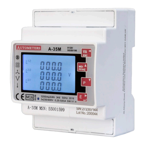
Autometers Systems HORIZON HT-1095 User manual
Autometers Systems
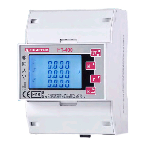
Autometers Systems A-35M User manual
Autometers Systems
Autometers Systems HORIZON HT-400 User manual
Autometers Systems
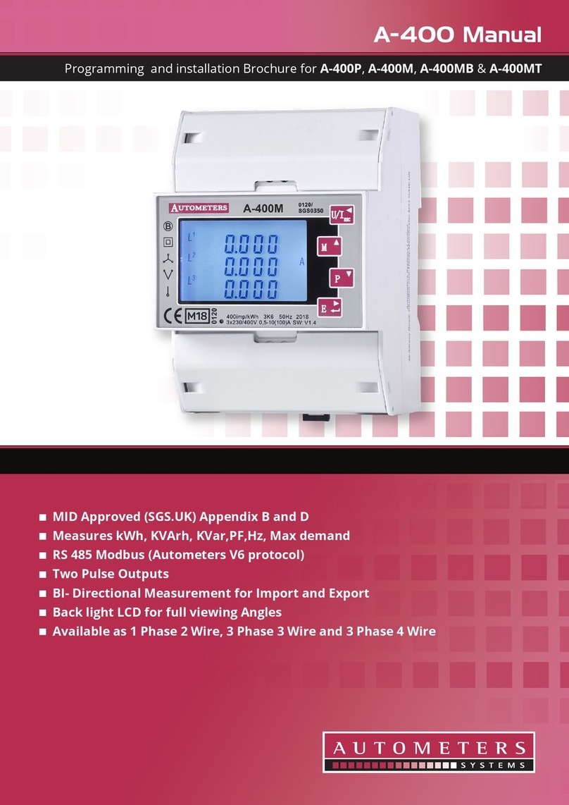
Autometers Systems A-400 Series User manual
Autometers Systems
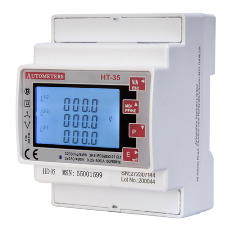
Autometers Systems HORIZON HT-35 User manual
Autometers Systems
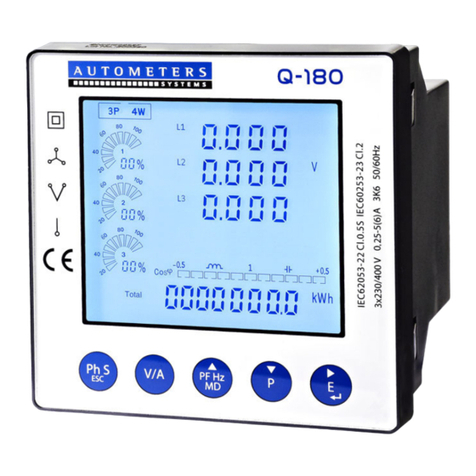
Autometers Systems Q-180 User manual
Autometers Systems
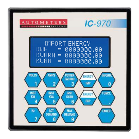
Autometers Systems IC 970 Installation instructions
Autometers Systems
Autometers Systems A-45 Series User manual
Autometers Systems
Autometers Systems HORIZON HT-35 User manual
Autometers Systems
Autometers Systems ADP3-80C User manual
