Pressure Transmitter
F-18
TPS30
TPS20
KT-302H
PTF30
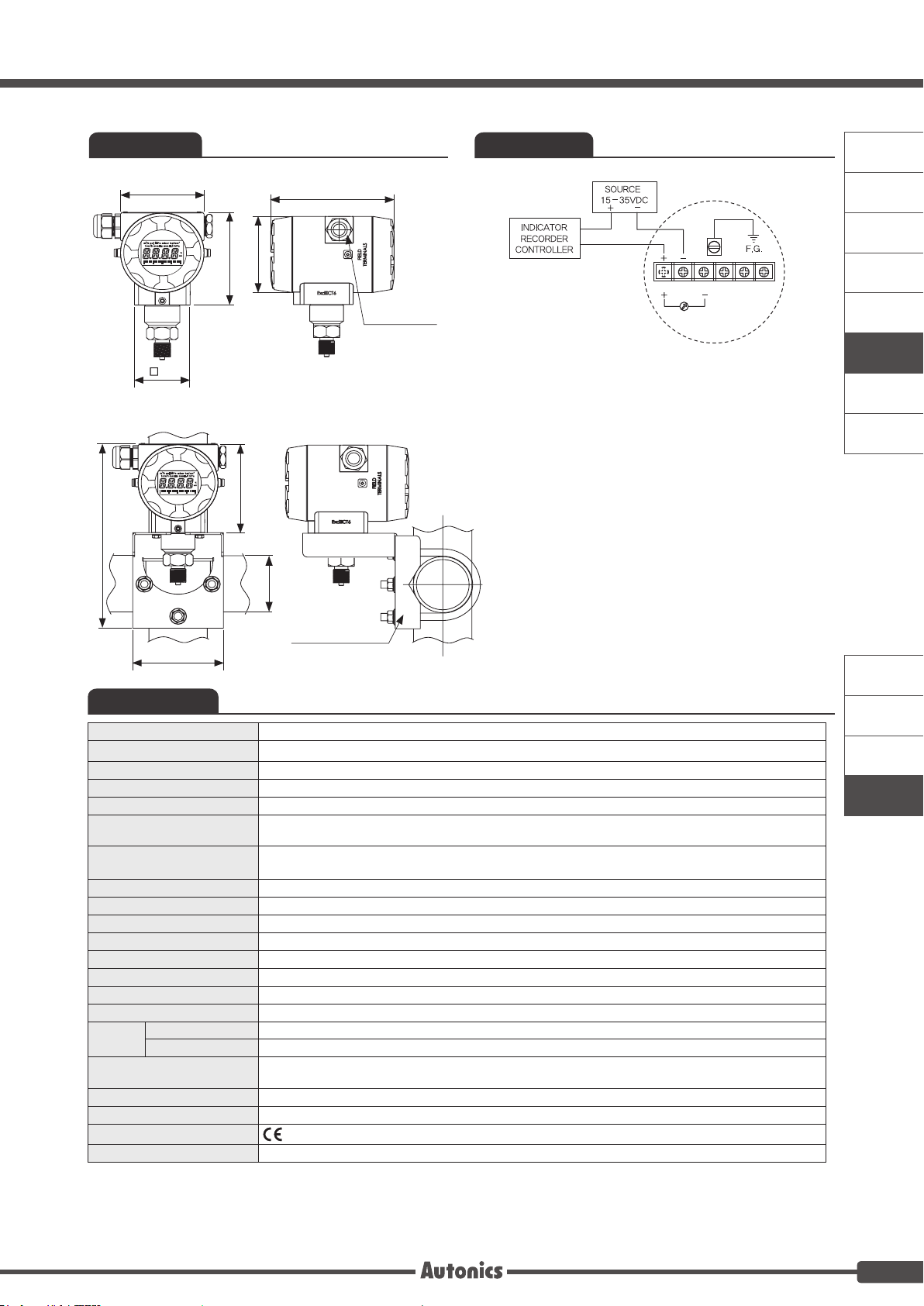
A. Recorders
B. Indicators
C. Converters
D. Controllers
E. Thyristor
Power
Controllers
F. Pressure
Transmitters
G. Temperature
Transmitters
H. Accessories
It corrects the error of display value for 100% input.
•Setting range: 0.900 to 1.100
For DC4-20mA current output, this function is set to
display value for current output.
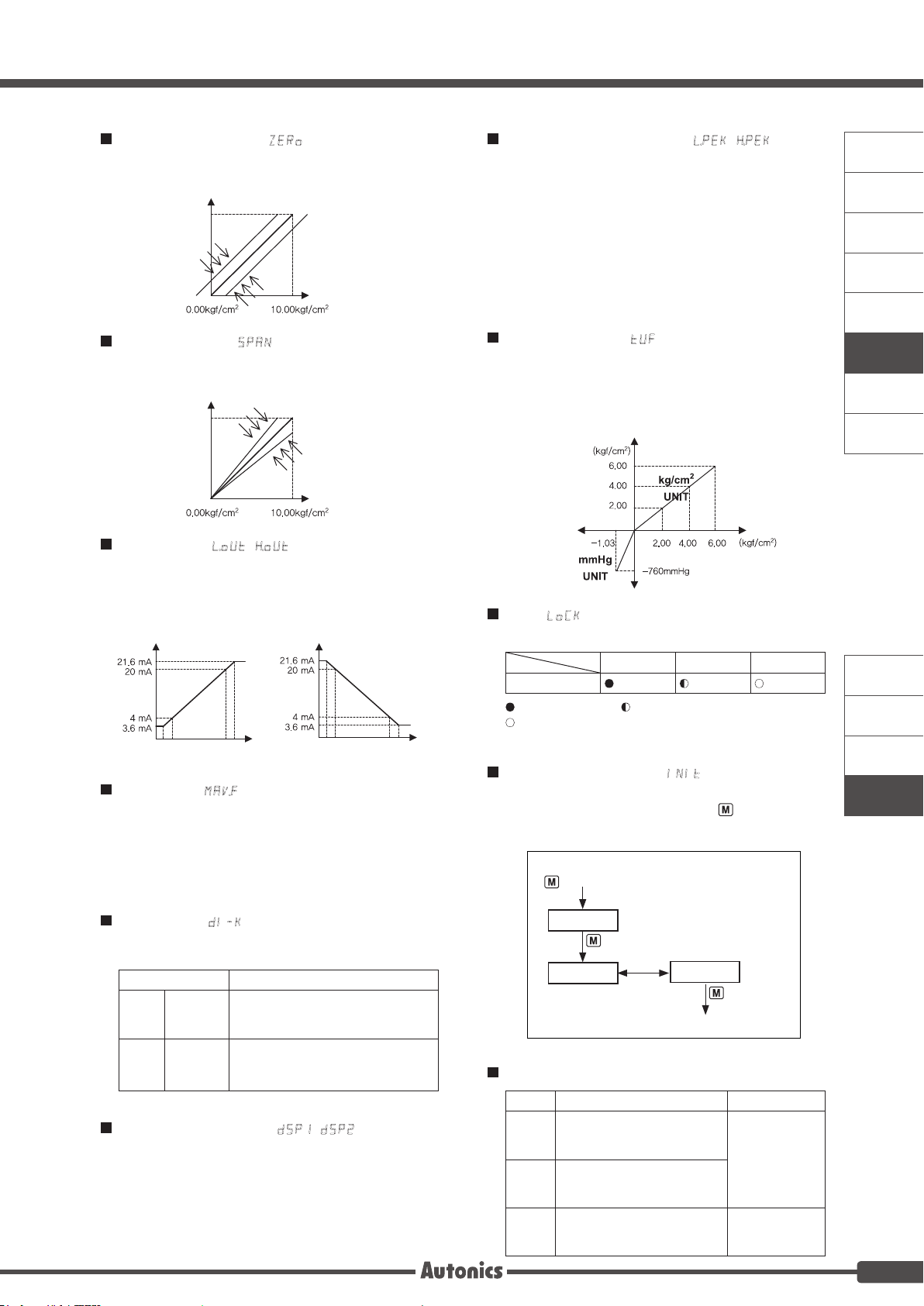
Set the display value for DC4mA [ lOUT] and the display
value for DC20mA [ hOUT].
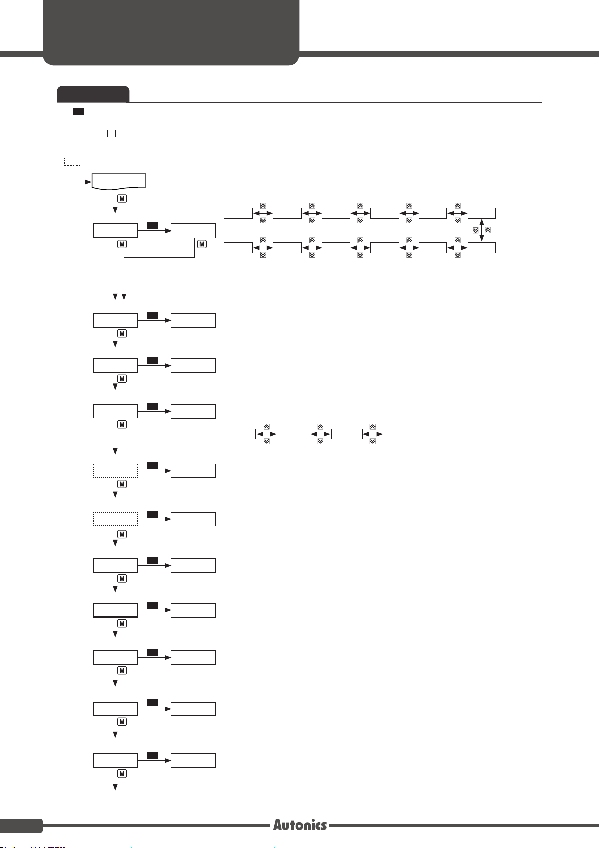
By front keys operation (D.IN3: 4 + 3 for 3 sec), one of
two functions executes as the below table.
Select one for display 1 and display 2 among PV, OUT,
lPEK, hPEK. Set DSP1 and DSP2 differently and it
displays two different values in turn for 2 sec. When
selecting lPEK(hPEK), the left (or the right) of output
scale bar graph ashes for 0.5 sec.
Function Operation
HOLD
Display
Hold
Temporarily indicated value is stopped
in order to conrm indicated value in
unstable input.
Z-TM
Zero-point
adjustment
It is same function as [ZERO]. When
executing this function, you can check
and change correction value at ZERO.
Display Descriptions Troubleshooting
HHHH
Flashes when measured
pressure is higher than the
'pressure range'. Adjust measured
pressure within
the 'pressure
range'.
LLLL
Flashes when measured
pressure is lower than the
'pressure range’.
ERR Flashes when there is error to
SV
Re-set it after
checking the
setting conditions
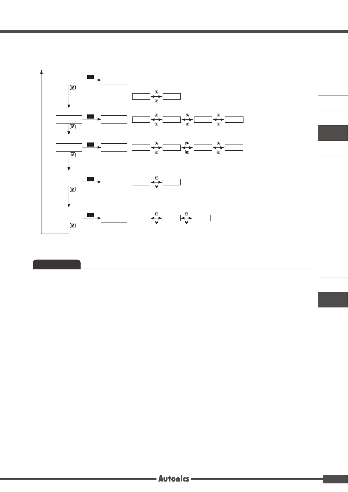
Slope correction [ SPAN]
Lock [ LOCK]
Parameter initialization [ INIT]
Error
Output scale [ lOUT, hOUT]
Digital filter [ MAvF]
Digital input [ DI-K]
Multi-display selection [ DSP1, DSP2]
O FF LOc1 LO c2
Parameter
: Enable to check/set, : Enable to check, disable to set,
: Disable to check
In LO c 2, only the LOCK parameter displays.
It limits to check parameter set value and to change it.
To initialize all parameter as factory default, supply the
power to the product with pressing the key and 1 key
at the same time and it enters initialization parameter.
For compound pressure model, this function displays the
input pressure which is below atmospheric pressure by
mmHg unit. It displays the input pressure atmospheric
pressure or over atmospheric pressure by the set pressure
unit.
Two unit function [ TUF]
This function is to save high/low peak to check the
invisible abnormal condition of system. Select this function
display selection [ dSP1, dSP2] parameter.
When the high/low peak is out of the temperature range, it
displays HHHH or LLLL.
To initialize high/low peak, press the 4, 3 keys at the
same time for 3 sec at [ hPEK] or [ lPEK].
In this case, peak value is the present input value.
High/Low peak monitoring [ lPEK, hPEK]
Digital lter is able to display stably and output the noise
from input line and irregular signals. This unit applies
moving average digital lter and display cycle is same.
•Setting range: 01 to 16
※ When setting as 01, digital lter function does not run.
It corrects the error of display value for 0% input.
•Setting range: -999 to 999
Zero-point correction [ ZERO]
lOUT hOUT lOUT hOUT
NO YES
CLR
Supply the power with pressing the
+ 1 keys at the same time.
Completes initialization.
3
4
Input
Output
Output
Input
Output Output
Input Input
Input
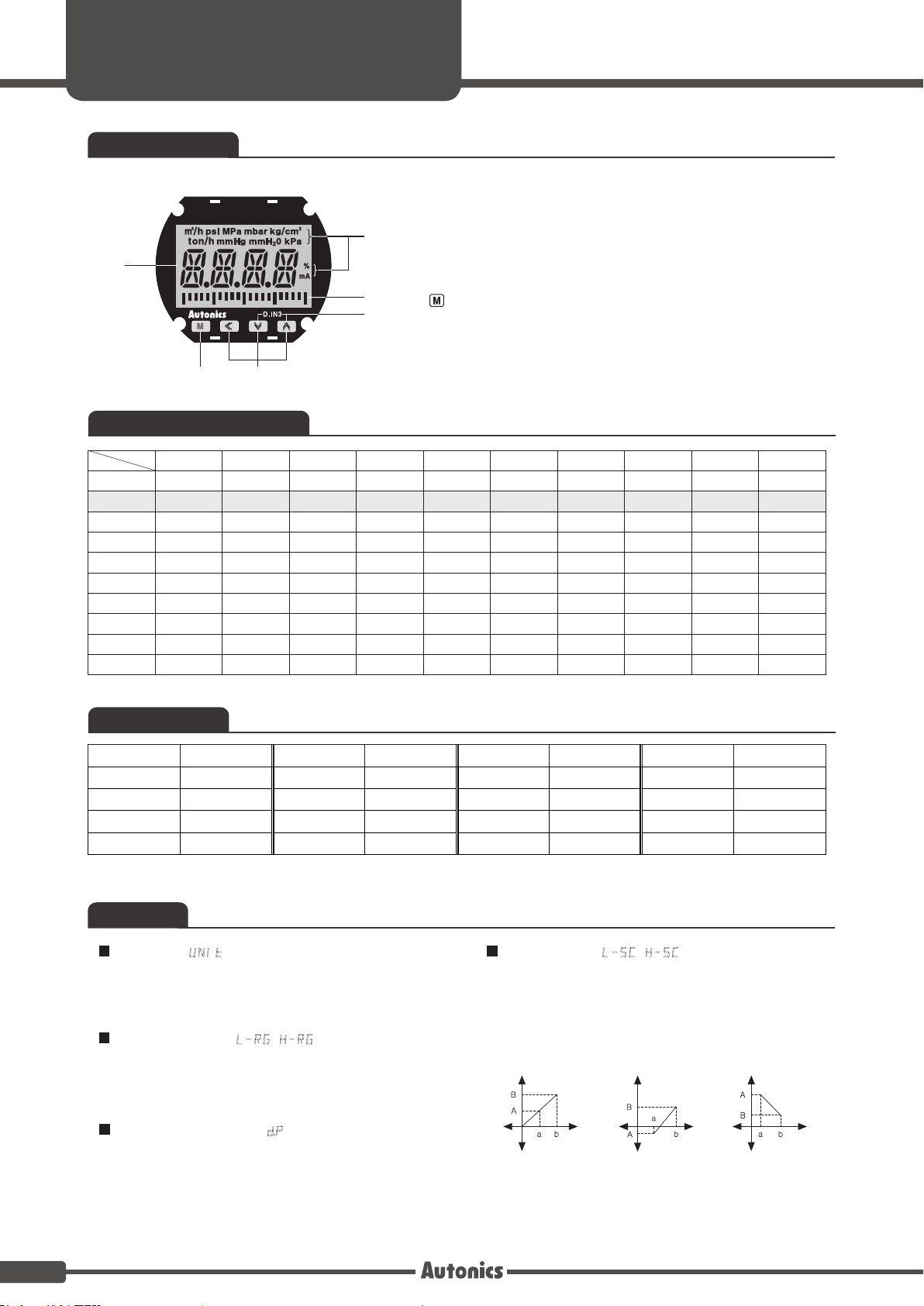
Display