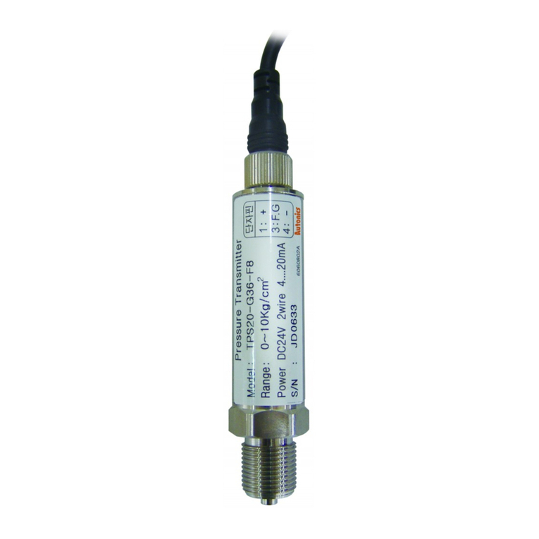
Autonics TPS20 Series User manual

-|Transparent Guide|-
TCD210188AB
Non-Indicating
Pressure Transmitters
TPS20 Series
PRODUCT MANUAL
For your safety, read and follow the considerations written in the instruction
manual, other manuals and Autonics website.
The specications, dimensions, etc are subject to change without notice for product
improvement Some models may be discontinued without notice.
ᜢ
Features
• Excellent corrosion resistance with stainless steel housing
• High accuracy ±0.3% F.S.
• Various connection method
- Head type, DIN connector type, connector cable type
• Various user friendly function
- Built-in zero-point, span adjustment (head type)
Safety Considerations
• Observe all ‘Safety Considerations’ for safe and proper operation to avoid hazards.
• symbol indicates caution due to special circumstances in which hazards may
occur.
Failure to follow instructions may result in serious injury or death.
01.
Failure to follow this instruction may result in personal injury, economic loss or re.
02.
Failure to follow this instruction may result in explosion or re.
03. Do not disassemble or modify the unit.
Failure to follow this instruction may result in re or electric shock.
Failure to follow instructions may result in injury or product damage.
01.
Failure to follow this instruction may result in product damage.
02.
Failure to follow this instruction may result in re or product damage.
03.
the unit.
Failure to follow this instruction may result in product damage.
04.
into the unit.
Failure to follow this instruction may result in re or product damage.
05.
Failure to follow this instruction may result in explosion or re.
06.
not use for corrosive medium.
Failure to follow this instruction may result in product damage.
07.
Failure to follow this instruction may result in re or electric shock.
• Follow instructions in ‘Cautions during Use’.
Otherwise, it may cause unexpected accidents.
• Power supply should be insulated and limited voltage/current or Class 2, SELV power
supply device.
• When installing the unit on pipe line, use the hexagon part of connections not to turn
the unit with a pipe wrench. Do not use the unit with strong vibrations.
• Store the unit at the place without moisture, dust, and vibration.
• This product is not needed to take maintenance because there is no moving part. But
it needs to take maintenance once a year as below instructions even though inside of
pressure pipe is normally clean.
1. Check the broken status of outside.
2. Check the pressure slot, cleanliness inside, and corrosion state.
3. Short each terminal and check the insulation resistance between the case and
power.

-|Transparent Guide|-
• M12 Connector cable: C□D3-2 / C□D3-5
• Product • Instruction manual
• When removing a sensor for maintenance, follow the below instructions.
1. Replace an O-ring which is used once.
2. Be sure that diaphragm part is not damaged.
• Switch or circuit breaker should be installed nearby users for convenient control.
• The unit cannot be repaired due to disassembled structure.
• The unit is xed with bolt and nut at the both sides of case. Do not press excessive load
(≈ 300 kg/cm²), or it may cause damage to the unit.
• This unit may be used in the following environments.
- Indoor / Outdoor (in the environment condition rated in ‘Specications’)
- Altitude max. 2,000 m
- Pollution degree 2
- Installation category II
This is only for reference, the actual product does not support all combinations.
For selecting the specied model, follow the Autonics website .
TPS20 -
G: Gauge pressure
A: Absolute pressure
F8: G3/8 (standard, PF)
P2: R1/2 (with adapter, PT)
P8: R3/8 (with adapter, PT)
ZZ: Others
1: Head type
2: DIN connector type
3. Connector cable type
Customized pressure range
Number: rated pressure range (unit: kgf/cm2)
10 to 0.2 -
20 to 0.5
30 to 1 0 to 1
40 to 2 0 to 2
50 to 7 0 to 7
60 to 10 0 to 10
70 to 20 0 to 20
80 to 35 0 to 35
90 to 70
-
A0 to 100
C0 to 200
F0 to 300
H0 to 350
M-1.03 to 0
O-1.03 to 1
Q-1.03 to 7
V-1.03 to 10
X-1.03 to 20
Y-1.03 to 35
ZUser pressure range
01) The pressure range is set to customized pressure range. (select 'Z' at ③ Rated pressure range)
Connections
Connector
Pin
+
-
Pin
1 +
2 -
3N.C
F.G.
Pin
1 +
2N.C
3F.G.
4 -
• In case of head type, remove the top cover.
15 - 35 VDCᜡ
+V
GND
Dimensions
• Unit: mm, For the detailed drawings, follow the Autonics website.
21
18
61
14
87
84
HEX24
Ø26
HEX27 21
18
8
37.3
81
Ø30
46.5
G3/8 71.5
HEX22
21 80.5
71.5
M12 Connector
8
18
Ø24
G3/8

18, Bansong-ro 513Beon-gil, Haeundae-gu, Busan, Republic of Korea, 48002
-|Transparent Guide|-
Fault
No outputs
Check the power supply.
Check the polarity (+, -) when wiring cable.
Check the connection part.
Abnormally uctuating output
Check the power supply.
Check the supplied pressure.
Check the pressure line.
Out of zero point output value
Check the power supply.
Check the load resistive value of current output type for
a receiver is over 600 Ω.
Check the measuring point and transmission distance.
Check the line resistance is below 600 Ω.
Series TPS20
Gas, liquid, uid (except corrosive environment of SUS316)
Gauge pressure Absolute pressure Compound pressure
0 to 0.2, 350 kgf / cm2
(dierent by model)
0 to 1.0, 35 kgf / cm2
(dierent by model)
-1.03 to 0, 35 kgf / cm
2
(dierent by model)
300 % of max. rated pressure
≤ 100 ms
Protection circuit Reverse polarity protection circuit
≥ Industrial plug 5 N
Material Sealing: SUS316, O-ring: uoro rubber, diaphragm: SUS316,
connection: SUS316
Connection +, -
Case structure Drip-proof structure
ᜢ
≈ 320 g (≈ 350 g), based on head type
01) It is dierent by model. Refer to 'Ordering Information'.
15 - 35 VDCᜡ
90 to 110% of rated voltage
≤ 50 mA
DC 4 - 20 mA
Linearity ± 0.3 % F.S. (-10 to 50 ℃), ± 0.5 % F.S. (50 to 70 ℃)
Hysteresis ± 0.3 % F.S.
Temp. Zero Shift ± 0.03 % F.S.
Temp. Span Shift ± 0.03 % F.S. (at 25 ℃)
Load resistance ≤ 600 Ω
≥ 100 MΩ (500 VDCᜡ megger)
Between the charging part and the case: 500 VACᜠ 50 / 60 Hz for 1
minute
Vibration 1.5 mm amplitude at frequency of 10 to 55 Hz in each X, Y, Z
direction for 2 hours
Shock 95 m/s2
-10 to 70 ℃, storage: -10 to 70 ℃ (no freezing or condensation)
Ambient humidity 5 to 95% RH, storage: 5 to 95% RH (no freezing or condensation)
Pressure Conversion Table
Pa 2 mmH2O bar
Pa 10.000010197 0.007501 0.101972 0.00014504 0.00001 0.0002953
298066.5 1 735.5592 10000.0005 14.223393 0.980665 28.959025
133.3224 0.001359 1 13.595099 0.019337 0.001333 0.039370
mmH2O9.80665 0.000099 0.073556 1 0.00142 0.000098 0.002896
6894.733 0.070307 51.71475 703.016716 1 0.068947 2.036014
bar 100000.0 1.019716 750.062 10197.1626 14.503824 1 29.529988
3386.388 0.034532 25.40022 345.315507 0.491156 0.033864 1
• 1,000,000 Pa = 1,000 kPa = 1 MPa
• For detailed information, refer to the 'M8/M12 Connector Cable' manual.
Power Connector 1 Connector 2 Feature Model
DC
M12 (Socket-
Female)
4-pin
3-wire 2 m PVC CID3-2
5 m CID3-5
DC
M12 (Socket-
Female)
4-pin, L type
3-wire 2 m PVC CLD3-2
5 m CLD3-5
Other Autonics Transmitter manuals
Popular Transmitter manuals by other brands

Festo
Festo SDAT-MHS-SV Series operating instructions

Kramer
Kramer 610T user manual

Michell Instruments
Michell Instruments Pura 2-Wire user manual

Evikon
Evikon PluraSens E2670-PID user manual

Katronic Technologies
Katronic Technologies KATflow 150 Quick start guides

Datcon
Datcon DT7001 operating instructions

Viatran
Viatran 510 Installation data manual

Scott Instruments
Scott Instruments 4688IR Series Safety, Setup, Operation & Maintenance Manual

Hall Technologies
Hall Technologies DSCV1-70-TX user manual

Superior Broadcast
Superior Broadcast SBFM100-SS user manual

Enersound
Enersound T?500 user manual

SV
SV STRC-600 quick start