Autowel DRAGON-350A User manual

THYRISTOR
THYRISTORTHYRISTOR
THYRISTOR
CO
COCO
CO
2
22
2
/MAG/MIG WELDER
/MAG/MIG WELDER/MAG/MIG WELDER
/MAG/MIG WELDER
DRAGON-350A
DRAGON-350ADRAGON-350A
DRAGON-350A
DRAGON-500A
DRAGON-500ADRAGON-500A
DRAGON-500A
DRAGON-650A
DRAGON-650ADRAGON-650A
DRAGON-650A
User
UserUser
User
Manual
ManualManual
Manual

CONTENTS
CONTENTSCONTENTS
CONTENTS◀ ▶
◀ ▶◀ ▶
◀ ▶
1. PRODUCT INTRODUCTION
2. CONFIGURATIONS and SPECIFICATIONS
3. INSTALLATION
4. HANDLING and OPERATION
5. SAFETY INSTRUCTION
6. MAINTENANCE and INSPECTION
7. TROUBLE SHOOTINGS
8. WELD CONDITION
9. SYMBOLS
10. DIAGRAMS
Before using welding machine, users have to read
the all contents described by manual to have better
quality of weld, and to reduce maintenance works.
1. Product Introduction
1. Product Introduction1. Product Introduction
1. Product Introduction
Autowel DRAGON- 350(500/ 650) sustains excellent stability under
the changes of input power or surrounding temperature by
adopting of the high responsive thyristor feedback and MICOM
type, so it is suitable in automatic welding and high- speed
welding.
2. Configurations and specifications
2. Configurations and specifications2. Configurations and specifications
2. Configurations and specifications
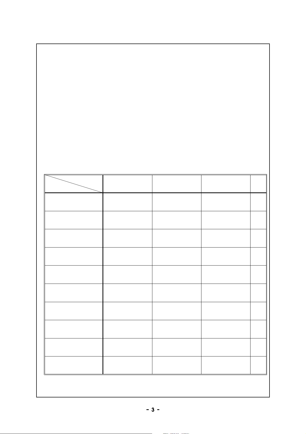
2- 1. Configuration
2- 1. Configuration2- 1. Configuration
2- 1. Configuration
Name
Type DRAGON- 350A DRAGON- 500A DRAGON- 650A Q'ty
WELDING POWER DC 350A DC 500A
(Gouging)
DC 650A
(Gouging) 1
WIRE FEEDER (0.9)1.2φ(1.2)1.4φ(1.2)1.6φ1
TORCH 350A, 3M 500A, 3M 650A, 3M 1
Gas Gage CO
2
(110V) CO
2
(110V) CO
2
(110V) 1
Welding cable 5M 5M 5M 1
Earth cable 35SQ, 3M 50SQ, 3M 70SQ, 3M 1
Tip (0.9)1.2φ(1.2)1.4φ(1.2)1.6φ3
Gas Diffuser for 350A for 500A for 500A 3
Insulator for 350A for 500A for 500A 3
Nozzle for 350A for 500A for 500A 3
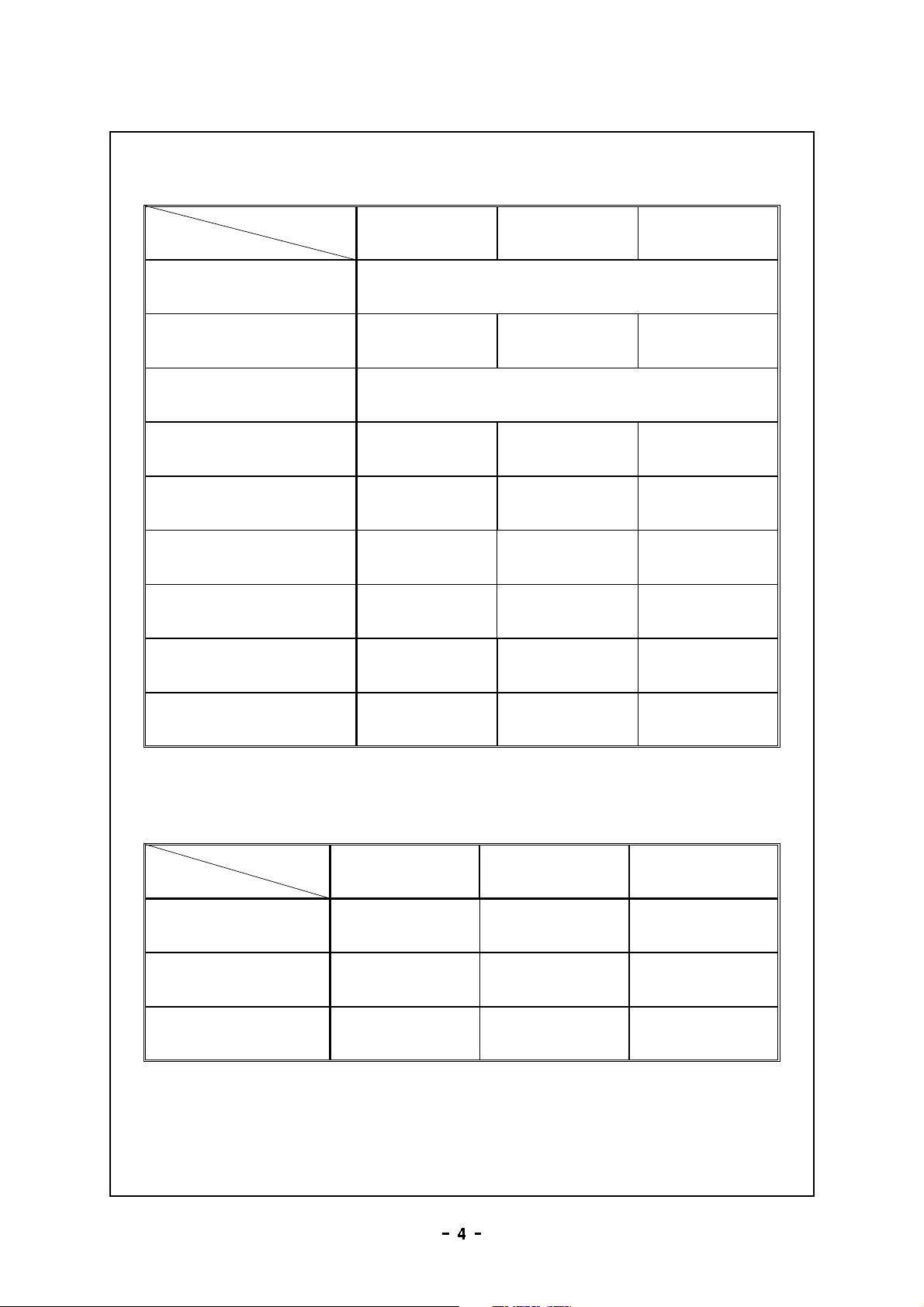
2- 2. Standard Specification
2- 2. Standard Specification2- 2. Standard Specification
2- 2. Standard Specification
Item Type DRAGON- 350A DRAGON- 500A DRAGON- 650A
Input Voltage 3P, AC 220/ 380/ 440V selected
Input Power 18.5KVA 32KVA 45KVA
Frequency 50/ 60㎐
Output Current 50 350A~60 500A~80 650A~
Max. No- load Voltage 53V 65V 70V
Load Voltage 16 34V~16 42V~16 50V~
Use Rate 60 % 70% 80%
Dimension (WXDXH) 420X640X750 510X700X770 510X700X860
Weight 115kg 186kg 205kg
2- 3. Electrical Apparatus
2- 3. Electrical Apparatus2- 3. Electrical Apparatus
2- 3. Electrical Apparatus
Item Type DRAGON- 350A DRAGON- 500A DRAGON- 650A
NFB 60A 75A 100A
1st Cable 10SQ or above 16SQ or above 25SQ or above
Grounding Cable 10SQ or above 16SQ or above 25SQ or above
3. Installation
3. Installation3. Installation
3. Installation
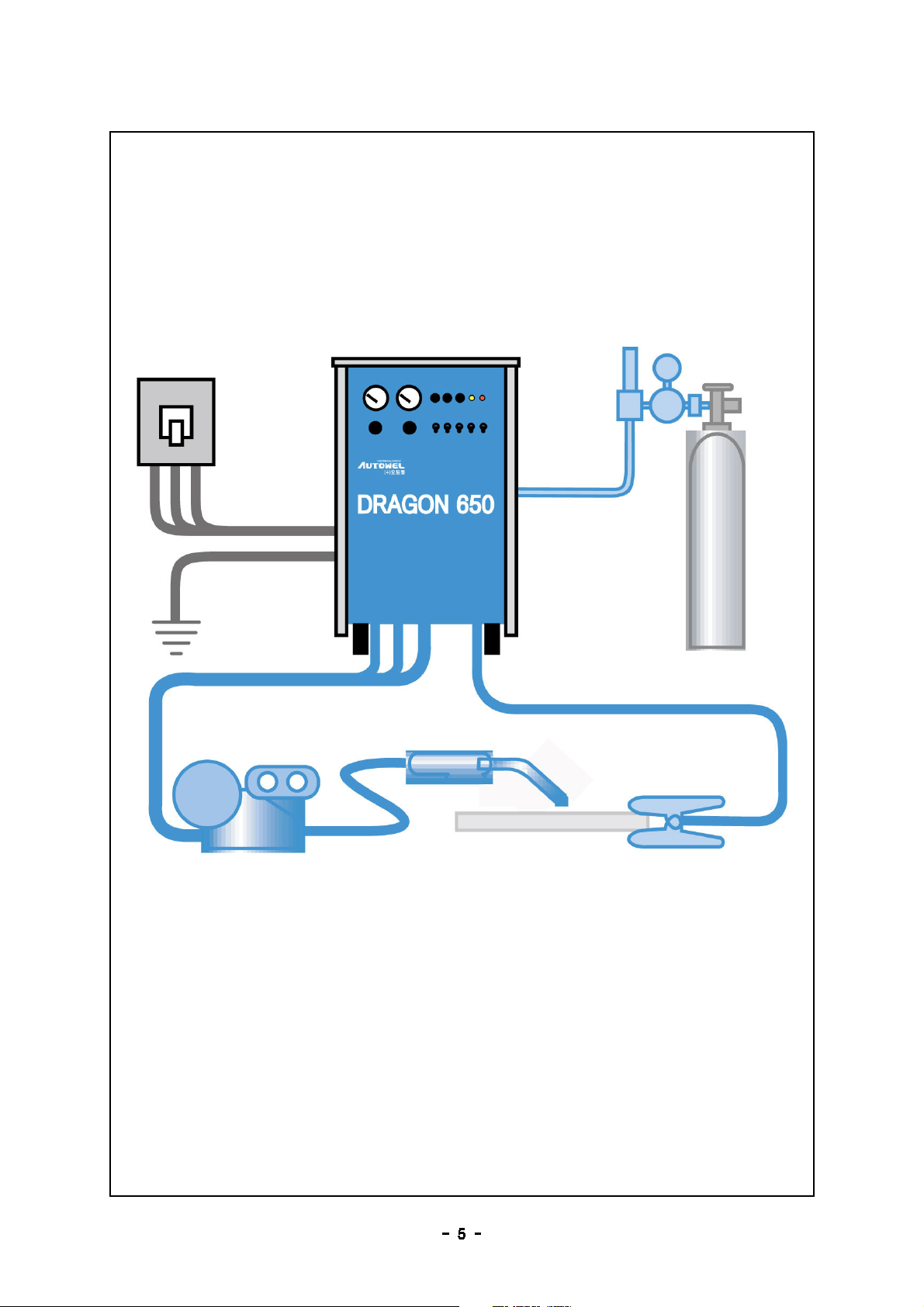
3- 1. Installation diagram
3- 1. Installation diagram3- 1. Installation diagram
3- 1. Installation diagram
Fig1. Full installation diagram
Fig1. Full installation diagramFig1. Full installation diagram
Fig1. Full installation diagram

3- 2. Location of installation
3- 2. Location of installation3- 2. Location of installation
3- 2. Location of installation
1) The inside of a house that there is a little moisture or dust.
2) The area far from each welders or wall more than 30cm.
3) The area that can avoid direct ray of sun, wind or rain.
4) The area where the surrounding temperature is in - 10 40~ ℃
range
5) The area that can install at the flat floor of stable construction
3- 3. Cautions in grounding
3- 3. Cautions in grounding3- 3. Cautions in grounding
3- 3. Cautions in grounding
1) The welder must be grounded, or electrical current of the case
causes the unstability of operation and accidents.
2) Connect grounding conductive cable which is 10SQ or more to
the grounding terminal which is marked "Grounding". During
the grounding work, make sure to off the on/ off switch in the
switch board, and afterward connect the ground cable.
3) When the base metal is placed on insulator such as wood, the
base metal must be grounded.
4) When there swimming pool or pond between the earth of
power source switch board and the earth of welder, leakage
current may flow to the pond or swimming pool. So in such
place, please connect grounding to both grounding points in
parallel so that the leakage current flow through the cable.
3- 4. Ventilation
3- 4. Ventilation3- 4. Ventilation
3- 4. Ventilation
1) Welding fume and gas are very bad for the health. They may
deal a person a fatal damage or cause death.
2) CO
2
arc- welding resolves shield gas, CO
2
in high temperature
and produces few carbon monoxide. Therefore, please ventilate
or wear the oxygen supply system or mask always when
welding is carried out in a small space.
3) If the ventilation is insufficient, please, install the dust collector
or support ventilation system.

3- 5. Movement Method
3- 5. Movement Method3- 5. Movement Method
3- 5. Movement Method
1) Separate welder and input power before moving welder.
2) Separate power unit, output, and earth cable before moving
welder.
3) No control or no contact below the equipment when it is
moved by hoist or forklift truck.
4) Use the adequate carriage to carry the welder.
3- 6. Connection of electrical sys
3- 6. Connection of electrical sys3- 6. Connection of electrical sys
3- 6. Connection of electrical sys
(
((
(Off the on/ off switch in the switch board
Off the on/ off switch in the switch boardOff the on/ off switch in the switch board
Off the on/ off switch in the switch board)
))
)
Even one point of defective connection may cause
unsatisfactory welding quality. Please tighten the connection
cables firmly with tool.
1) Connection of input power : Please connect referring to the
Fig. 1. Install NFB for your safety. When you install the electric
leafage breakers, please install the one which can detect more
than 30mA.
2) Connection of output : Referring the Fig 1, please connect
the torch to (+), base metal to (- ).
3) Connection of control cable : Connect the control cable to
remote terminal in order to control welding wire feeder and
remote control box.
4) Ground : Ground terminal is behind of the inverter welder.
The connection cable shall be 10SQ or above.
5) When it is used with engine generator, please use bigger
engine generator than the one specified in 2- 2. standard
specification. Unstable output power voltage may cause the
stop by activating the abnormal voltage detection circuit of
welder. And please start the engine generator when the power
switch of welder is off mode. An instant applying of excessive
voltage may cause malfunction of welder.
3- 7. Gas Connection
3- 7. Gas Connection3- 7. Gas Connection
3- 7. Gas Connection
1) Connect CO
2
gas to pressure regulator.
2) Connect outlet hose of gas pressure regulator to the gas inlet
behind of in the welder.
3) Connect the heat plug of gas pressure regulator to the
dedicated receptacle behind of the welder. (The receptacle is
dedicated to pressure regulator)
4) Install the gas container in the place where is no direct ray of
sun. And it is recommended to fix it to a supporter for safety.
5) For the good welding quality, please use high purity gas.
4. Handling and operation
4. Handling and operation4. Handling and operation
4. Handling and operation
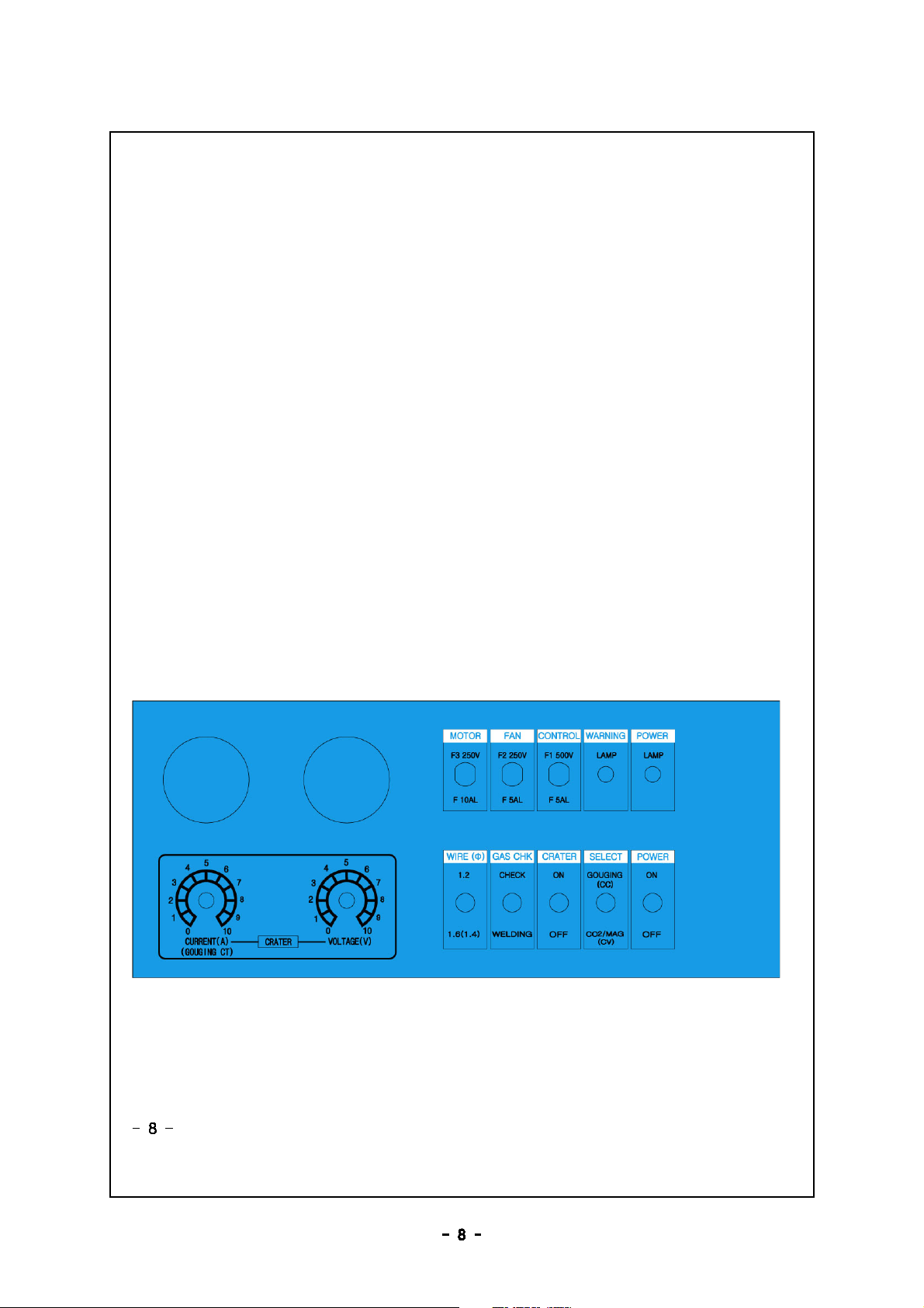
4- 1. Front panel and name
4- 1. Front panel and name4- 1. Front panel and name
4- 1. Front panel and name
DRAGON- 350A / 500A / 650A
DRAGON- 350A / 500A / 650ADRAGON- 350A / 500A / 650A
DRAGON- 350A / 500A / 650A

4- 2. Function and explanation
4- 2. Function and explanation4- 2. Function and explanation
4- 2. Function and explanation
1) POWER switch : power on/ off of welder. When on mode, fan
motor and magnetic switch is in standby mode. (power saving
function)
2) SELECT switch : Select CO2/ MAG/ M welding function (CV)
and gouging function (CC)
3) CRATER switch : self containing is activated in ON mode,
and enables to treat crater prior to completion of welding,
and the welding is available only when it is OFF and torch is
ON.
4) GAS check switch : On for checking gas volume, otherwise
select OFF.
5) WIRE (select wire diameter) switch : It balances voltage-
current according to the wire diameter for welding with same
voltage. (If the wire diameter is bigger, the feeding speed is
slow).
6) POWER LAMP : It turns on when the on/ off switch is ON.
(It indicates the welder is powered)
7) WARNING LAMP: It is turned on upon overheating and
overloading, and it stops operation. For restart, reset the
power switch.
8) CONTROL FUSE : use 5A fuse , for protection of control
circuit.
9) FAN FUSE : use 5A fuse , for protection of fan motor.
10) MOTOR FUSE(feeder motor fuse) : use 10A fuse, for
protection of feeder motor
11) CRATER C’T VOLUME(adjust crater current) :It adjusts current
value when crater switch is ON, and adjusts gouging current
value when gouging is selected.
12) CRATER VOLT VOLUME(adjust crater voltage) : When crater

switch is ON, crater voltage can be adjusted.
13) CURRENT METER : It indicates output current value in welding
( in case of no- load, it is not indicated)
14) VOLTAGE METER : It indicates output voltage in welding
(If the torch switch is ON under no- load condition, no- load
voltage value is indicated )
15) REMOTE : It connects to the feeder control box.
16) Torch terminal (+) : Connect to the torch terminal of feeder.
17) Earth terminal (- ) : Connect to the base metal.
18) Gas terminal : Connect to gas terminal of the feeder.
19) Remote control box : It is installed on the feeder.
a) Inching switch : It extrudes wire to the end of torch
quickly when welding wire is replaced.
b) Welding voltage volume : Adjust welding voltage.
c) Welding current volume : Adjust welding current.
(When gouging is selected in the feeder, it functions to
adjust gouging current)
d) Weld selection switch : Select CO2/ MAG/ MIG weld and
GOUGING function
20) Back panel:
a) 3 phase power input terminal
b) Power input switching terminal box : Select 220V/ 380V/
440V (In case of switching terminal box input power, open
the upper panel and change the terminal of single phase
auxiliary transformer)
c) HEATING power source of gas regulator : 110V
d) HEATER protection fuse of gas regulator : 2A glass tube
fuse

4- 3. Cautions in handling
4- 3. Cautions in handling4- 3. Cautions in handling
4- 3. Cautions in handling
1) Torch angle by welding direction
Incline the torch 10~ 15° toward the welding
direction, and afterward, you can weld by
"forward method", or "Backward method"
In general, "Forward method" is used considering
with the friction of arc and protection of welded
surface by gas.
2) Welding torch
If the welding torch is bent excessively, smooth wire feeding is
not available, and welding condition is damaged due to
reduced current. Please do not bend cable forcefully.
3) Standard use rate
Use rate 350A 500A 650A
60% 350A
70% A 500A
80% A A 650A
90% A A A
100% 200A 350 600A
5. Safety instruction
5. Safety instruction5. Safety instruction
5. Safety instruction
1) Power source device : Install one on/ off switch for one welder.
2) Terminal connection : Fasten the connection part for smooth
current carrying in welding. Loose fastening may cause cable
damage or wasting power.
3) Ground : Apply class 3 grounding
4) Surrounding environment : Please avoid the location where
moisture and dust is too much, and surrounding temperature is
too high. Select place where air is ventilated well. Especially,
ventilation relates to the use rate.
6. Maintenance and inspection
6. Maintenance and inspection6. Maintenance and inspection
6. Maintenance and inspection
Input power switch must be OFF when internal and external
terminal are checked. The condenser of welder internal circuit
is charged, so please wait 5 minutes after completing welding
work, and afterward open the case and check.
6- 1. Check items by time
6- 1. Check items by time6- 1. Check items by time
6- 1. Check items by time
Before
welding
1) Does the switch work well ?
2) Does the cooling fan works well according to the On
and Off mode, and is the air well ventilated to
forward?
3) Is there any abnormal vibration, noise or smell?
4) Any thing wrong in weld cable and connecting area?
5) Is there any defective insulation on cable?
3 6 month~
1) Remove dust : Remove dusts by blowing out dry
compressed air. Especially, transformer, reactor and
semiconductors shall be cleaned carefully.
2) Check of electrical contact area : Fasten bolts tightly
and remove foreign material such as rust with file or
sand paper so that sufficient contact is available
between metals.
3) Check if ground is done well.
Annual total
maintenance
1) Based on maintenance schedule, replace expendable
supplies, repair case and reinforce worn cables.
2) Insulation resistance shall be 1 mega ohm or above,
or maintenance and repair are required.
7. Trouble shootings
7. Trouble shootings7. Trouble shootings
7. Trouble shootings
Step Phenomenon Reason Remedy
1
Power lamp is not
turned on when power
switch is ON.
Poor lamp Replace lamp
Poor contact of the 1st input part Contact test
Poor fuse Replace fuse
Poor NFB Replace NFB
2
Only FAN works. Poor torch switch Replace torch switch
Power lamp is on, but
fan does not work. Poor fan motor Replace fan motor
3 Gas doesn' t come out.
No gas or no connection Check and replace
Poor solenoid valve Replace valve
Defect in control PCB Request A/ S
Poor torch switch Replace torch switch
4Gas comes out
continuously.
Gas comes out even if power is off. Remove foreign
material from valve
Poor solenoid valve Replace valve
Defect in control PCB Request A/ S
Poor torch switch Replace torch switch
5
Weld wire is not fed
even though inching
switch is pressed.
Poor motor fuse Replace fuse
Poor motor Replace motor
Poor PCB relay Replace relay
Wire is not fed when
torch switch is ON.
Poor torch switch Replace torch switch
Poor PCB Request A/ S
6Voltage and current are
not adjustable.
Poor remote contact Check and replace
Poor control volume Replace
Poor PCB Request A/ S
7
Under no- load
condition, voltage meter
does not work and no
ARC.
Poor torch switch Replace torch switch
Poor PCB Request A/ S
Under no- load
condition, voltage meter
works but no arc.
Broken torch cable Replace torch cable
Poor contact of earth able Check
8Crater is not
controllable.
Poor control volume Replace
Poor PCB Request A/ S
8. Weld condition
8. Weld condition8. Weld condition
8. Weld condition
8- 1. In case of improper welding conditions
8- 1. In case of improper welding conditions8- 1. In case of improper welding conditions
8- 1. In case of improper welding conditions
8- 2. Clearance between base metal and tip
8- 2. Clearance between base metal and tip8- 2. Clearance between base metal and tip
8- 2. Clearance between base metal and tip
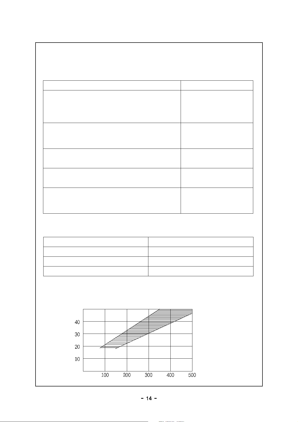
8- 3. Relation between weld current and voltage
8- 3. Relation between weld current and voltage8- 3. Relation between weld current and voltage
8- 3. Relation between weld current and voltage
Reason Remedy
Arc length is growing
Particle of spatter becomes bigger
Bead width is widening
The length and height of weld penetration become
smaller.
Arc voltage is too high
Wire sticks to the base metal and too many spatters.
Bead width becomes narrow.
The depth and height of weld penetration becomes
bigger.
Arc voltage is too low
Particle of spatter becomes smaller
Bead width is widening
The depth of weld penetration becomes bigger.
Welding current is too high
Bead width becomes narrow.
The length and height of weld penetration become
smaller.
Welding speed is fast.
Particle of spatter becomes smaller
the number of spatter decreases.
The depth and height of weld penetration becomes
bigger.
Current density of wire is
high.
Wire diameter (mm) Clearance (mm)
0.9 1.0~10 15~
1.2 15 20~
1.6 25 30~

8- 4. Reasons and remedy for defects of CO
8- 4. Reasons and remedy for defects of CO8- 4. Reasons and remedy for defects of CO
8- 4. Reasons and remedy for defects of CO
2
22
2
welding
weldingwelding
welding
Type
TypeType
Type Main reason
Main reasonMain reason
Main reason Remedy
RemedyRemedy
Remedy
1. Blow holes
1. Blow holes1. Blow holes
1. Blow holes
1) No feed gas comes out
2) Air mixed in feed gas
3) Insufficient coating effect due
to strong wind
4) Carbon dioxide soaked in
5) Foreign material in welding part
6) Nozzle diameter is too small
7) Arc is too long
1) Check the gas cylinder, valve and pressure
regulator
2) Check the connection part of gas tube
3) Make measure for wind in wind speed
2m/ sor more
Remove spatter from the nozzle
4) Use gas of welding purpose
5) Clean the welding area
Remove feed oil from roller and wire
6) Select proper nozzle diameter
7) Lower voltage
2. Under cut
2. Under cut2. Under cut
2. Under cut
1) Wrong grounding location
2) Welding speed is too fast
3) Arc length is long
4) Welding current is too much
1) Ground onto the first location
2) Slower the welding speed
3) Keep arc length short
4) Select proper welding current
3. Overlap
3. Overlap3. Overlap
3. Overlap
1) Too low arc voltage comparing
to welding current
2) Welding speed is low
1) Raise arc voltage
2) Speed up the welding speed
4. Curve bead
4. Curve bead4. Curve bead
4. Curve bead
1) Wire pressurizing lever does not
work
2) Distance between tip and the
base metal is too far.
3) Tip mounting is not proper
4) Wire bent
5) Tip is worn out
1) Adjust control screw of pressurizing lever
2) More than 10~ 15 times of wire diameter
3) Adjust mounting angle in order to go into
the wire guide directly
4) Straighten wire
5) Replace contact tip
5. Crack
5. Crack5. Crack
5. Crack 1) Improper welding conditions
(high current, high speed)
2) Wire approaching angle is too
small
3) Too much containing of carbon
and other metals in the base
metal
4) Too much moisture in gas
5) Quick electrical break of arc in
crater
1) Set proper condition
(Raise voltage, slow speed)
2) Increase wire approaching angle
3) Preheating and after- heating treatment
4) Use gas of welding purpose
5) Treat with crater
(add up enough deposition metal)
Blow holes
Blow holesBlow holes
Blow holes
Overlap
OverlapOverlap
Overlap
Crack
CrackCrack
Crack
Under cut
Under cutUnder cut
Under cut
8- 5. CO
8- 5. CO8- 5. CO
8- 5. CO
2
22
2
(semi)auto weld condition
(semi)auto weld condition(semi)auto weld condition
(semi)auto weld condition
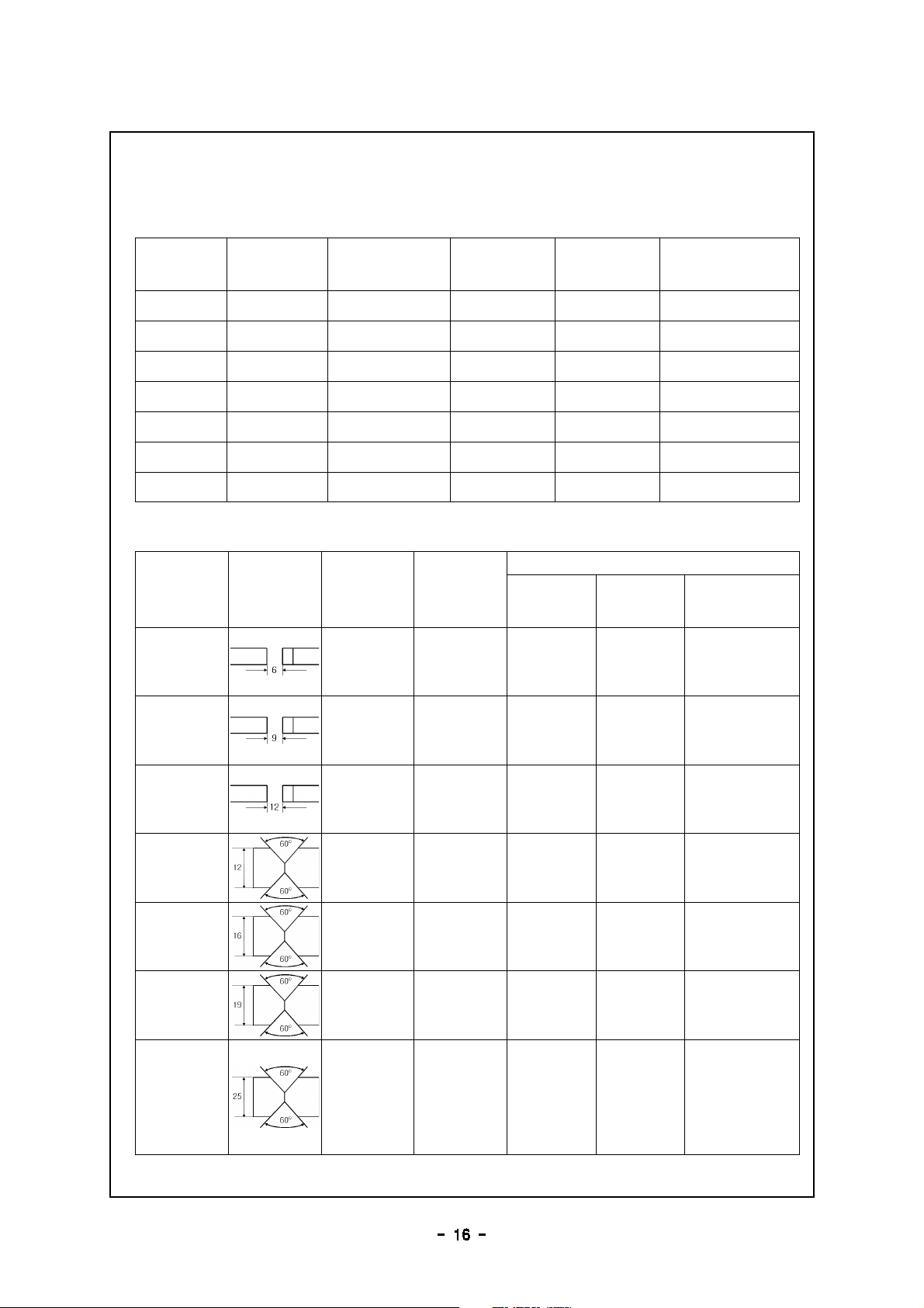
1) 1form butt weld
short ARC weld①
Hi- Current②weld
Thick
(mm) gap (mm) Wire dia.
(mm) CT (A) Volt (V) weld speed
(cm/ min.)
1.6 0 0.8 1.0~90 18 45
2.0 0.5 0.8 1.0~100 18 50
2.3 1.0 0.8 1.2~120 19 55
3.2 1.2 0.8 1.2~140 19 50
4.5 1.5 1.2 160 23 50
6.0 1.5 1.2 260 26 50
8.0 1.5 1.2 320 32 50
thickness
(mm) improved pieces Wire dia.
(mm)
weld condition
CT (A) Volt (V) SP(cm/ min)
6 2 1.2
1.2
190
210
19
20 25
9 2 1.6 340
360
33.5
34 50
12 2 1.6 430
450
36
37 50
12 2 1.2 310
330
32
33 55
16 2 1.6 410
430
34.5
36 45
19 2 1.6 470
490
37
38 43
25 2 1.6 480
500
38
39 40

2) Horizontal fillet weld
3) vertical down fillet weld
4) Edge weld (Thin steel plate)
5) CO
2
ARC for welding wire (solid wire)
thickness
(mm)
weld width
(mm)
wire dia.
(mm)
weld current
(A)
weld voltage
(V)
weld speed
(cm/ min)
1.6 3.0 0.8 1.0~130 20 50
2.0 3.0 1.0 1.2~130 20 45
2.3 3.0 1.0 1.2~140 20.5 45
3.2 4.0 1.0 1.2~170 21 45
4.5 4.5 1.2 230 23 50
6.0 6.0 1.2 290 28 50
9.0 7.0 1.2 330 33 45
12.0 11.0 1.6 400 38 25
thickness
(mm)
width
(mm)
Wire dia.
(mm)
weld current
(A)
weld voltage
(V)
weld speed
(cm/ min)
1.2 3.0 0.8 1.0~100 19 50
1.6 3.0 0.8 1.2~120 20 50
2.0 3.0 0.8 1.2~130 20 50
2.3 3.5 1.0 1.2~140 20.5 50
3.2 4.0 1.0 1.2~160 21 45
4.5 4.5 1.2 230 23 55
6.0 6.0 1.2 290 28 50
8.0 8.0 1.2 320 32 55
plate thick
(mm)
wire dia.
(mm)
current
(A)
voltage
(V)
speed
(cm/ min)
Tip/ base
M
(mm)
gas
volume
( / min)ℓ
1.6 0.9 65 75~16 17~40~10 10 15~
2.3 0.9 80 100~19 20~40~10 10 15~
3.2 1.2 130 150~20 22~35~10 15~10 15~
4.5 1.2 150 180~21 23~30~10 15~10 15~
type impurities uses wire dia
(mm)
C Si Mn P S
KC- 25 0.10 0.22 0.62 0.015 0.009 mild
steel
hi- tensio
n weld
0.8, 0.9
KC- 26 0.10 0.45 0.98 0.013 0.010 1.0, 1.2
KC- 28 0.11 0.82 1.45 0.014 0.016 1.6

6) Horizontal fillet weld(thin steel plate)
8- 6. MAG (semi)auto weld condition
8- 6. MAG (semi)auto weld condition8- 6. MAG (semi)auto weld condition
8- 6. MAG (semi)auto weld condition
1) Vertical down butt weld
2) Horizontal fillet weld
plate thick
(mm)
wire dia
(mm)
current
(A)
voltage
(V)
speed
분(cm/ )
tip- base
M
(mm)
gas
volume
( / min)ℓ
0.8 0.9 60 70~16 17~40 45~10 10 15~
1.2 0.9 80 90~18 19~40 50~10 10 15~
1.6 0.9 90 110~19 20~45 50~10 10 15~
2.3 0.9 100 130~20 21~45 50~10 10 15~
2.3 1.2 120 150~20 21~45 50~10 10 15~
3.2 1.2 150 180~20 22~45 50~10 15~10 15~
4.5 1.2 200 250~24 26~40 50~10 15~10 15~
thick
(mm) gap (mm) wire dia (mm) current (A) voltage (V) weld speed
(cm/ min)
0.4 0 0.4 20 15 40
0.6 0 0.4 0.6~25 15 30
0.8 0 0.6 0.8~30 40~15 40 55~
1.2 0 0.8 0.9~60 70~15 16~30 50~
1.6 0 0.8 0.9~100 110~16 17~25 60~
3.2 1.0 1.5~0.8 1.2~120 140~16 17~25 30~
4.0 1.5 2.0~1.0 1.2~150 160~17 18~20 30~
thick
(mm) width (mm) wire dia (mm) current (A) voltage (V) weld speed
(cm/ min)
0.6 2.0 0.4 0.6~30 40~14 40 50~
1.0 2.0 2.5~0.6 0.8~40 60~14 15~40
1.6 3.0 0.6 0.8~90 100~15 16~40 55~
2.4 3.5 0.8 1.0~110 120~16 17~35 40~
3.2 4.0 0.8 1.2~135~17 18~35 35~

9. Symbols
9. Symbols9. Symbols
9. Symbols
9- 1. Symbols to indicate switch or control position
9- 1. Symbols to indicate switch or control position9- 1. Symbols to indicate switch or control position
9- 1. Symbols to indicate switch or control position
N°
N°N°
N° SOURCE
SOURCESOURCE
SOURCE SYMBOL
SYMBOLSYMBOL
SYMBOL
FUNCTION,
FUNCTION,FUNCTION,
FUNCTION,
KEYWORD OR
KEYWORD ORKEYWORD OR
KEYWORD OR
PHRASE
PHRASEPHRASE
PHRASE
APPLICATION
APPLICATIONAPPLICATION
APPLICATION
1. IEC
604175007 On (power)
To indicate connection to the
mains, at least for mains switches
or their positions, and all those
cases where safety is involved.
2. IEC
604175008 Off (power)
To indicate disconnection from the
mains, at least for mains switches
or their positions, and all those
cases where safety is involved.
9- 2. Symbols to indicate electrical connection
9- 2. Symbols to indicate electrical connection9- 2. Symbols to indicate electrical connection
9- 2. Symbols to indicate electrical connection
N°
N°N°
N° SOURCE
SOURCESOURCE
SOURCE SYMBOL
SYMBOLSYMBOL
SYMBOL FUNCTION, KEYWORD
FUNCTION, KEYWORDFUNCTION, KEYWORD
FUNCTION, KEYWORD
OR PHRASE
OR PHRASEOR PHRASE
OR PHRASE APPLICATION
APPLICATIONAPPLICATION
APPLICATION
1. IEC
604175005 Plus; positive polarity To signify positive polarity
2. IEC
604175006
Minus; negative
polarity To signify negative polarity
3. IEC
604175019
Protective earth
(ground)
To signify the equipment
connection point for the
protective earth (ground)
4. IEC
604175939
Power supply type of
electric device
On device or equipment
e.g. on arc welding
equipment
9- 3. Symbols to indicate type of torch
9- 3. Symbols to indicate type of torch9- 3. Symbols to indicate type of torch
9- 3. Symbols to indicate type of torch
N°
N°N°
N° SOURCE
SOURCESOURCE
SOURCE SYMBOL
SYMBOLSYMBOL
SYMBOL FUNCTION, KEYWORD
FUNCTION, KEYWORDFUNCTION, KEYWORD
FUNCTION, KEYWORD
OR PHRASE
OR PHRASEOR PHRASE
OR PHRASE APPLICATION
APPLICATIONAPPLICATION
APPLICATION
1. MIG/ MAG Torch To signify a MIG/ MAG
torch
9- 4. Symbols to indicate processes
9- 4. Symbols to indicate processes9- 4. Symbols to indicate processes
9- 4. Symbols to indicate processes
N°
N°N°
N° SOURCE
SOURCESOURCE
SOURCE SYMBOL
SYMBOLSYMBOL
SYMBOL FUNCTION, KEYWORD
FUNCTION, KEYWORDFUNCTION, KEYWORD
FUNCTION, KEYWORD
OR PHRASE
OR PHRASEOR PHRASE
OR PHRASE APPLICATION
APPLICATIONAPPLICATION
APPLICATION
1. Submerged arc
welding
To signify submerged arc
welding
9- 5. Symbols to describe the type of power source
9- 5. Symbols to describe the type of power source9- 5. Symbols to describe the type of power source
9- 5. Symbols to describe the type of power source
N°
N°N°
N° SOURCE
SOURCESOURCE
SOURCE SYMBOL
SYMBOLSYMBOL
SYMBOL
FUNCTION,
FUNCTION,FUNCTION,
FUNCTION,
KEYWORD OR
KEYWORD ORKEYWORD OR
KEYWORD OR
PHRASE
PHRASEPHRASE
PHRASE
APPLICATION
APPLICATIONAPPLICATION
APPLICATION
1. IEC
604175031
Direct current
(DC)
To signify that power source
delivers direct current
2. IEC
604175032
Alternating
current (AC)
To signify that power source
delivers alternating current
9- 6. Symbols to indicate protective component and class
9- 6. Symbols to indicate protective component and class9- 6. Symbols to indicate protective component and class
9- 6. Symbols to indicate protective component and class
of protection
of protectionof protection
of protection
N°
N°N°
N° SOURCE
SOURCESOURCE
SOURCE SYMBOL
SYMBOLSYMBOL
SYMBOL FUNCTION, KEYWORD
FUNCTION, KEYWORDFUNCTION, KEYWORD
FUNCTION, KEYWORD
OR PHRASE
OR PHRASEOR PHRASE
OR PHRASE APPLICATION
APPLICATIONAPPLICATION
APPLICATION
1. IEC
60974- 1
Suitable for welding in
an environment with
increased hazard of
electric shock
To signify a welding power
source suitable for welding
in an environment with
increased hazard of
electric shock
9- 7. Examples of combinations of symbols
9- 7. Examples of combinations of symbols9- 7. Examples of combinations of symbols
9- 7. Examples of combinations of symbols
SYMBOL
SYMBOLSYMBOL
SYMBOL FUNCTION, KEYWORD
FUNCTION, KEYWORDFUNCTION, KEYWORD
FUNCTION, KEYWORD
OR PHRASE
OR PHRASEOR PHRASE
OR PHRASE APPLICATION
APPLICATIONAPPLICATION
APPLICATION
Caution! Read the
instruction manual
To indicate a hazard and
signify that the instruction
manual should be read
This manual suits for next models
2
Table of contents
Other Autowel Welding System manuals


Popular Welding System manuals by other brands

ESAB
ESAB Caddy Mig C160i instruction manual

Bug-O Systems
Bug-O Systems STW-3000 Instructions and parts manual

Chicago Electric
Chicago Electric 68888 quick start guide

Migatronic
Migatronic PILOT 1500 HP instruction manual

Magneti Marelli
Magneti Marelli Clima-Tech Plus user manual

Miller
Miller Maxstar 300 owner's manual


